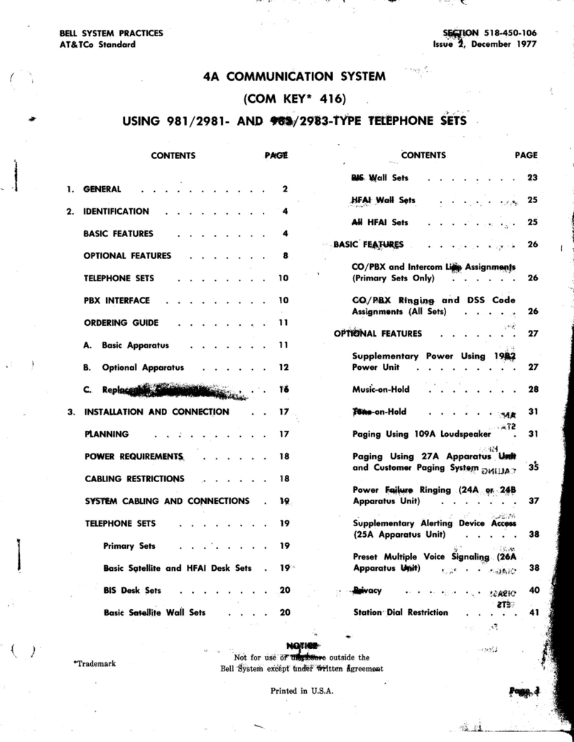
Bell System Com Key 416 Instruction manual

I
BELL
SYSTEM
PRACTICES
AT
&
TCo
Standard
SECTION
S18-450-1
06
Issue 3,
January
1980
4A COMMUNICATION
SYSTEM
(COM KEY*
416)
IDENTIFICATION, INSTALLATION, CONNECTION, OPERATION, AND MAINTENANCE
CUSTOMER EQUIPMENT
CONTENTS
PAGE
CONTENTS
PAGE
1.
GENERAL
3
POWER
REQUIREMENTS
21
2.
IDENTIFICATION
7
Supplementary
Power
22
BASIC
FEATURES
7
CABLING
RESTRICTIONS
23
OPTIONAL
FEATURES
10
SYSTEM
CABLING
AND
CONNECTIONS
24
TELEPHONE
SETS
11
TELEPHONE
SETS
24
PBX
INTERFACE
12 A. Primary Sets
24
FCC
REGISTRATION
12 B. Basic Satelli
te
and
HFAI
Desk Sets
24
ORDERING
GUIDE
12
c.
BIS
Desk Sets
24
A. Telephone Sets 12 D.
Ba
si
c Satellite Wall Sets 25
B. Optional
Apparatus
15 E. BIS Wall Sets
28
c. Optional Components
16
F.
HFAI
Wall Sets
30
D.
Interconnection Components 17 G.
All
HFAI
Sets
30
E. Replaceable Components 17
BASIC
FEATURES
31
3.
INSTALLATION
AND
CONNECTION
20
A.
CO
/
PBX
and
Intercom Li
ne
Assignments
(Primary Sets Only)
31
PLANNING
20
B.
CO
/PBX
Ringing
and
DSS
Code
ELECTRICAL
PROTECTION
21
Ass
i
gnments
(All
Sets)
31
ELECTRO
-
MAGNETIC
INTERFERENCE
21
SUPPLEMENTARY
POWER
32
OPTIONAL
FEATURES
33
*Tradema
rk
of
AT&T. A. Music-On-Hold
33
NOTICE
Not
fo
r use or disclosure outside the
Be
ll
System except under written agreement
Printed
in
U.S.A.
Page
1
518-450- -·o3_1980-01-01.jpg Scanned
by
Frank Harrell (Cowboy Frank Castle Rock, Colorado
6/11/2017/20:35:04

SECTION
518-450-1
06
CONTENTS PAGE
B.
Tone-On-Hold
34
C.
Paging
(Telephone
Company
Provided
System)
36
D. Paging (Interface With Customer-Provided
System)
39
E.
Power
Failure Ringing
40
F.
Supplementary
Alerting Device Access
43
G.
Preset
Intercom Voice
Signaling
45
H.
Privacy 47
I.
Station
Dial Restriction
49
J. Personal Line
49
K.
Code
Busy
DSS
Key
54
L.
4A
Speakerphone
54
M.
Repertory Dialing 57
N. External Ringing
57
0.
Special
Handsets
58
FINAL
SYSTEM
CONNECTIONS
58
4.
METHOD
OF OPERATION
59
ANSWERING
CALLS
USING
HANDSET
59
PLACING
CALLS
USING
HANDSET
60
HOLD
OPERATION
60
Page
2
CONTENTS
ANSWERING
CALLS
USING
BUll
T-IN
SPEAKERPHONE
PLACING
CALLS
USING
BUILT-IN
PAGE
60
SPEAKERPHONE 61
Built-In
Speakerphone
Operating
Features 61
ANSWERING INTERCOM
CALLS
AT
HFAI
STATION 61
HFAI
Operating
Features
CALLING
AN
HFAI
STATION
4A SPEAKERPHONE OPERATION
MISCELLANEOUS
OPERATING TECHNIQUES
5.
MAINTENANCE
DIAGNOSTIC
PROCEDURES
DISASSEMBLY
AND
ASSEMBLY
OF
TELEPHONE
SETS
A.
Faceplate
B.
Upper
Housing
C. Lower Housing (All
Satellite
Desk Sets)
D. Wall Housing (All
Satellite
Wall Sets)
E.
Lower Housing (Primary Sets)
0:35:17
62
62
62
63
64
64
65
65
65
71
71
71

I
I
I
518
CONTENTS
PAGE
REMOVAL
AND
INSTALLAT
I
ON
OF
COMPONENTS 73
A.
DSS
Key
74
B. Dial 75
C.
Loudspeaker
Asse
mbly
78
D. Handset
Jack
79
E.
Recall
Key
79
F. Loudspeaker Volume Control
80
G.
Line
Key
80
H.
BIS
Module 81
I.
HFAI
Modu
le
81
J. Amplifier
82
K.
Voice
-Signaling
In
terf
ace
C
irc
uit
82
L. Interconnect Field A
ss
embly 83
M.
Ba
se and
Log
ic A
ss
embly
84
N. Power Transformer 84
1.
GENERAL
1.
01
This section provides complete information
on
the
4A
Communication System
(COM
KEY 416) using 98112981-
and
983/2983-type
telephone sets.
1.
02
This secti
on
is reissu
ed
to:
• Add information relative to the Federal
CommunicationsCommission
(FCC)
Registration
Program
ISS
3,
SECT
ION 518-4
50
-106
• Show the
91B
connecting bl
ock
replacing
the
91A
(MD)
• Show the
33C
voice coupler replacing the
33A
(MD)
• Show the
30AM
apparatus
unit replacing
the
30A
(MD)
• Show the
19B4
power unit replacing the
19B2
(MD)
• Show the
2012D
transformer replacing the
2012B
(MD)
• Show the D-180980 music-on-hold kit of
parts
replacing the D-180730
(MD)
• Delete coverage of F-60591 Kit of
Parts
• Add information
on
electrical protection and
electro-magnetic interferen
ce
protection
• Refer to additional external ringers
• Cover use of special handsets
• Add new Table
A,
combining previous Tables
A and B
• Add new Table B
• Revise Table F
• Add new Fig.
7,
10,
26,
33, 39,
40,
and
46
• Revise Fig.
8,
9,
11, 12,
21, 24, 28,
32, 38,
43,
44,
48,
49,
50,
51,
and
52.
Since this reissue is a general revision,
no
revision
arrows have been used to denote significant changes.
1.
03 The
4A
System is a packaged, modular key
telephone system having a maximum capacity
of
16
stations with four common CO/PBX lines,
one personal CO/PBX line per telephone, and two
intercom paths. A wide selection of basic and
optional features is available (see
Part
2).
The
Pa
ge 3
•3
•32

SECTION
518-450-1
06
system includes five types of telephones:
(1)
primary sets,
(2)
basic satellite desk sets,
(3)
basic
satellite wall sets,
(4)
satellite sets with built-in
speakerphone (BIS), and
(5)
satellite sets with
hands-free answer
on
intercom (HFAI). Each
primary set contains the control circuitry for two
CO/PBX lines and one intercom path and the
power circuitry to serve itself and some combination
of
up
to seven satellite sets. The addition of a
second primary set doubles the capacity of the
system; up to seven more satellite sets can
be
connected, with each station in the system now
served
by
up to four CO/PBX lines and two intercom
paths. The satellite sets provide the same basic
services as the primary sets,
but
they
do
not
contain control and power circuits.
Caution
1:
The
4A
System
is
designed
to
operate
on
CO/PBX
loops
of
20
milliamperes
or
greater.
Caution
2:
The
4A
System
is
not
intended
for
installations
where
off-premises
extensions
are
required.
1.04 Because the control and power circuitry of
the
4A
System is contained in the primary
station sets, there is
no
need for separately mounted
key service units such as most key systems require.
The only equipment required in addition to the
telephone sets are interconnecting cables, blocks,
adapters, and small externally mounted units for
some optional features. Systems with many optional
features may require an externally mounted power
unit.
1.05 Each
4A
station can
be
programmed by the
customer to ring
on
any combination of the
common CO/PBX lines. All stations have access
to all common lines in the system; therefore, any
set can
be
assigned as the
attendant
station, if
one is required. Each station also has direct access
to the ten intercom codes.
1.06
All
4A
telephone sets are available with
either
rotary
or TOUCH-TONE® dialing.
The primary set is available only in a desk-type
model, but the basic satellite sets can
be
ordered
in both desk and wall configurations. The BIS
and HFAI sets are convertible from desk to wall
mounting
by
means of a kit of
parts
. There
are
a total of ten telephone set codes
in
the 980-series
(Table
A)
. Figures 1 through 5 illustrate typical
sets.
Page 4
1.07 The
4A
System derives its ac power from a
standard
117-volt 60-Hz source. The system
components
are
protected by a self-resetting thermal
cutout in the power supply of the primary station,
making separate fusing unnecessary. The
19B4
power unit, used when supplementary
de
power is
required, has both input and output fusing.
1.08 While the 980-series telephones provide more
optional features
than
the
830
series
(MD)
used with the earlier
4A
System (Section
518-450-105),
the two series are compatible and interchangeable.
They can coexist in the same system and 980-series
sets can
be
used to replace 830-series sets in
existing installations. However, if supplementary
power is required, the primary sets must
be
from
the
980
series.
Note:
In a mixed system, optional code
busy direct station selection (DSS) keys can
only give busy
indications
for
980-series
telephones.
1.09 Certain components and apparatus used with
the
4A
System have been rated
MD
and
replaced
by
new units. These units are listed in
Table
B.
Throughout the
rest
of this practice, all
references will
be
to the
current
versions of the
units,
unless
the procedures applying to the
MD
unit are different in any way; in the
latter
case,
both units will
be
given separate coverage.
1.10 Schematics
of
the telephone sets and apparatus
units of the
4A
System
are
contained in
SD-69856-01.
The
schematic
of
the
1A
transmitter-receiver (built-in speakerphone module)
is in SD-69800-01.
1.11 For additional information
on
the following
subjects, refer to the documents listed:
4A
Speakerphone-Section
512-700-100
33C
Voice
Coupler-Section
463-341-102
Adjunct Repertory
Dials-Section
501-164-201
KS-16301117
Relay-Section
463-110-100
KS-16626112 Relay
Set-Section
463-120-100
19B4
Power
Unit-Section
167-440-201
Wall-Mounting Fasteners-Section
080-720-105

ISS
3,
SECTION
518-450-106
I
TABLE A
SUMMARY
OF
4A
COMMUNICATION SYSTEM TELEPHONE
SETS
AND
OPTIONS
COMPONENT(SJ REQ
UIRED
Personal Line 30AM Apparatus Unit (Note
1)
D-180758 Kit
of
Parts
Privacy D-180729 Kit
of
Parts
Wall
Mounting D-180747 Kit
of
Parts
Code Busy DSS Key
664C
Key
Station
Restriction (Wiring Change Only)
Impaired Hearing G6BM Handset
Handset D-180851 Kit
of
Parts
Handset With More D-180413 Handset
Receive Gain Than G6BM D-180851 Kit
of
Parts
Weak Speech Handset G7BM Handset
D-180851 Kit
of
Parts
Set
G8BM Handset
Options
Noisy Location Handset D-180851 Kit
of
Parts
Acoustic
or
Inductive
G15A
llandset
Coupling Handset D-180851 Kit
of
Parts
G-Type Handset Equipped G4BM Handset
With
Shoulder
Rest D-180851 Kit
of
Parts
Long Loop, 3-dB Transmit G36AM Handset
Gain D-180851 Kit
of
Parts
External
Speakerphone
4A
Speakerphone
D-180732 Kit
of
Parts
Adjunct
Repertory Dial
Repertory
Dialing 870A1
or
2870A1
DlOY50
Cord
Built-In
Speakerphone
(Factory-Installed)
Hands-Free Answering (Factory-Installed)
on Intercom
Power Failure Ringing
248
Apparatus Unit
Supplementary
Alerting 25A
Apparatus
Unit
Device Access
KS-16626Ll2
Relay
0'
KS-16301L17 Relay
Alerti
ng
Device and its
Power Unit
Preset Intercom Voice 26A Apparatus Unit
Signaling
System Telephone
Company·
109A
Loudspeaker
Set
Options
Provided Paging System
Customer-Provided Paging 27A Apparatus Unit
System Interface
(Note
3)
Background
r.
·Jusic With Any 33C Voice
Coupler
Paging System
(Note
4)
Music-On-Hold 33C Voice
Coupler
(Note
4)
D-180980 Kit
of
Parts
Tone-On-Hold D-180731 Kit
of
Parts
External Ringing E1CM, S1AMP, or
LlAM
Ringer
Supplementary
Power
1984
Power Unit
Note
I: Mounted
external
to
telephone set.
Note
2:
Option
not
offered when
set
is
wall
mounted.
Note 3: KS-16626L12 relay may also be required.
Note
4:
Only
one
33C voice
coupler
is required per system.
DESK BASIC
SA
TELLITE
SATE
LLITE
981A03
TOUCH-
2981A02
SATELLI
TE
1983A01
(Note
2)
(Note
2)
(Note
2)
(Note
2)
(Note 2)
(Note
2)
(Note
2)
(Note 2)
518-450-106-i03_1980-01-05.jpg Scanned
by
Frank Harrell
(Cowboy
Frank) Castle Rock,
Colorado
6/11/2017
/20:36:09
HFAI
SA
TELLITE
(Note 2)
(Note 2)
(Note
2)
(Note
2)
(Note
2)
(Note 2)
(Note
2)
(Not
e 2)
(Note 2)
Page
5

SECTION
S18-4S0-1
06
Fig.
1-Primary
Telephone Set
Fig
.
3-Built-ln
Speakerphone
Satellite Telephone Set
Fig
.
2-Basic
Satellite Wall Telephone Set
Page
6
•
l518-450-106-i03_1980-01-06.jpg Scanned
by
Frank Harrell
(Cowboy
Frank) Castle Rock,
Colorado
6/11/2011/ 2 ·36:23

ISS
3,
SECTION
518-450-106
LEAD GUIDE
HFAI
MODULE
Fig.
4-Hands-Free
Answer on Intercom Satellite Telephone Set With Faceplate Removed
I
E1-Type
Ringers-Section
501-251-100
L1AM
Ringer-Section
501-258
-
101
S1AMP Tone
Ringer-Section
501-260-100
Electro-Magnetic Interface Protection-X-4235
2.
IDENTIFICATION
2.01 The
4A
System consists primarily of key
telephone sets and various connecting hardware
and cables. Basic operating features are supplied
as
part
of the telephone sets, while additional
1518-450-106-i03_1980-01-07.
jpg
apparatus, installed in the
sets
or externally,
provides optional features.
BASIC
FEATURES
2.02 The following features
are
provided in all
4A
System telephone sets and require
no
additional installation:
(a) Pickup, Hold,
and
Illumination-Standard
key system pickup, hold, and line
status
lamp indications, including flash
on
incoming
CO
/
PBX
line calls, steady on answered calls,
and wink-on-hold
are
provided. Systems with
one primary set are limited to two common
Page
7

SECTION S
18-450-
1
06
Fig.
5-Basic
Satellite Desk
Set
With
Faceplate
and
Upper
Housing Removed
CO/PBX lines; systems with two primary sets
can have up to four lines.
(b)
2-Path
Intercom
With
DSS-Two
paths
are provided for intercom calls, each associated
with
an
IC
button in
the
pickup key. A busy
path
is indicated
by
a steady lamp adjacent to
the
IC
button. The DSS buttons allow one-way
voice signaling of called stations without dialing.
A two-way conversation is established when
the
called
party
goes off-hook and picks up
the
intercom path. Ten DSS codes
are
available; in
systems with more
than
ten stations, codes
must
be
shared. The intercom code is
set
at
each
station
by
means of a programming switch
and
may
be
reprogrammed by the customer. Systems
with one primary
set
are limited to a single
intercom path; systems with two primary sets
have two paths.
Page
8
(c)
Automatic
Button
Restoration
(ABR)-Depressed
line or intercom buttons
are
mechanically returned to
the
unoperated
position when the handset is placed on-hook.
This prevents inadvertent intrusion into calls in
progress when handset is picked up and prevents
lines from being left bridged
after
a conference
call.
(d)
Built-In
Loudspeaker-The
built-in
loudspeaker is bridged across the handset
receiver when
the
locking
SPKR
button
is
operated, permitting
other
people in the
area
to
hear
both sides of a conversation. The loudspeaker
has a thumbwheel volume control
on
the front
of the telephone. This loudspeaker also receives
tone and voice signaling.
Note:
In BIS
and
HF
AI
sets
with
4A
speakerphone added, the bridging feature is
518-450-106-i03_1980-01-08.jpg Scanned
by
Frank Harrell
(Cowboy
Frank) Castle Rock,
Colorado
6/11/2017
/20:37:00

ISS
3,
SECTION
518-450-106
TABLE B
STATUS
OF
MANUFACTURE DISCONTINUED (MD) COMPONENTS AND APPARATUS
MD
UNIT
REPLACED REASON FOR
APPLICATION
OF
BY
CHANGE
MD
UNIT
Meet FCC Registration Previously used
unit
can
91A Connecting Block 91B Requirements in 4A be reused in any instal-
System lation
Meet FCC Registration Previously used
unit
can
24A Apparatus Unit 24B Requirements in 4A be reused in any instal-
System lation
Meet FCC Registration Previously used
unit
can
30A Apparatus Unit 30AM Requirements in 4A be reused in any instal-
System lation
Meet FCC Registration Previously used
unit
can
33A Voice Coupler 33C Requirements in 4A be reused in any instal-
System lation
D-180730 Music- Meet FCC Registration Previously used
unit
can
On-Hold Kit
of
D-180980 Requirements in 4A be reused in any instal-
Parts System lation
19B2 Power Unit 19B4 Meet New Underwriters Any installation
Laboratories Standards
2012B Transformer 2012D Design Improvement Any installation
disabled but equivalent service is provided by
the speakerphone.
(e)
Tone
Signaling-The
alerting signal for
incoming CO/PBX lines is a tone source
rather
than conventional ringing.
It
is supplied
through the built-in loudspeaker. Each station
can
be
individually programmed
by
the customer
to
be
tone signaled
on
any combination of incoming
CO
/
PBX
lines.
(f)
Voice
Signaling-Voice
signaling
rather
than ringing or tone is provided
on
the
intercom paths. The calling party alerts the
called station
by
voice while holding down the
appropriate
DSS
button. The called station
receives this voice signal through
its
built-in
loudspeaker. Multiple stations may
be
signaled
by
depressing more
than
one DSS button
at
a
time. When the called station picks up the
handset, the loudspeaker is attenuated.
(g)
Multiline
Conferencing-Two
or more
CO
/
PBX
lines can
be
conferenced
by
a station
by simultaneously depressing
the
associated
locking buttons. Transmission quality is degraded
as more lines are added.
Note:
Intercom lines cannot
be
conferenced
with
CO
/
PBX
lines.
(h)
Recall-The
R button, located below and
to the left of the dial
on
each set, has two
functions:
(1)
to drop a line and reoriginate dial
tone without going back on-hook and
(2)
to signal
[flash] the
attendant
when the
4A
System is
behind a
PBX
or Centrex. The R button should
be
used for these operations instead of depressing
Page 9
l518-450-106-i03_1980-01-09.jpg Scanned
by
Frank Harrell
(Cowboy
Frank) Castle Rock,
Colorado
6/11/2011/ 2 ·3 ·

SECTION
S18-450-1
06
..
the switchhook which will cause the line or
intercom buttons to restore.
(i)
Outgoing
Service
During
Power
Failure-Outgoing
CO/PBX calls can be
made from the
4A
System even when local
power has failed.
OPTIONAL
FEATURES
(TAB
LE
A)
2.03 The following
options
are
available
as
separately installed items or as features of
specific telephones:
(a)
Personal
Line-Each
station in the
4A
System can
be
provided with one noncommon,
personal CO/PBX line. Each such line requires
the installation of a separately mounted
30AM
apparatus
unit
which provides
standard
key
system
pickup, hold,
and
line
status
lamp
indications for
that
line. The personal line is
assigned to a button in the line pickup key. A
given personal line may be shared by more
than
one station in the system, and
it
will ring
at
every station where
it
is connected. Music- or
tone-on-hold is available as an option with this
feature.
(b)
TOUCH-TONE
Dialing-Rotary
dialing
can
be
replaced
by
TOUCH-TONE dialing
by ordering appropriate telephone codes. Rotary
dial
and
TOUCH-TONE dial
sets
may
be
intermixed in the
4A
System without additional
equipment.
(c)
Privacy/Privacy
Release-A
station
equipped with the optional privacy feature
is prevented from entering a CO/PBX call in
progress. Privacy is implemented
on
~per-station
basis by installation of a
D-180729
Kit of
Parts.
The station can
be
released from this condition
by
the operation of the privacy release feature
at
the
other
station(s)
on
the call. All 980-series
telephone sets have the factory-wired PRIV RLS
button, which should
be
designated' only when
at
least one station in the system has privacy
installed.
Note:
The privacy feature applies to all
CO/PBX lines but not to intercom lines.
(d)
Station
Restriction-Placing
of
all outgoing
CO/PBX calls from a station can
be
prevented
by shorting
bar
changes inside the set.
Page 10
(e)
Music
-
On-Hold-Music
from customer-pro-
vided music source is supplied to CO/PBX
lines placed
on
hold. Installation of one
33C
voice coupler per system and a
D-180980
Kit of
Parts
in each primary station and each
30AM
apparatus
unit
is required.
(f)
Tone-On-Hold-An
alternative
to
music-on-hold,
it
provides
intermittent
bursts
of tone to CO/PBX lines placed
on
hold. Installation
of a
D-180731
Kit of
Parts
in each primary station
and each
30AM
apparatus
unit
is required.
(g)
Supplementary
Alerting
Device
Access-The
operation of an external relay
to control bells, gongs, horns, etc,
by
incoming
ringing
on
CO/PBX lines
and/or
by
depression
of an assigned DSS button is provided. This
feature requires installation of a
25A
apparatus
unit, an external relay, and a signal with
its
power source.
(h)
Paging-Voice
announcements can
be
made
over
109A
loudspeaker sets or a customer-owned
and maintained paging system. The
latter
arrangement
requires the use of a
27A
apparatus
unit
to provide proper interface with the
4A
System. Background music may
be
provided
by
means of customer-provided music and a
33C
voice coupler (same source and coupler used for
music-on-hold). The paging path is activated
by
operation of a DSS button assigned to this
feature. The
109A
loudspeaker contains two
customer-accessible volume controls for adjusting
background music and paging volume; background
music is automatically muted during paging.
Note:
For normal voice inputs, the minimum
output of the
27A
apparatus
unit is -30 dBm
into
600
ohms.
(i)
Preset
Intercom
Multiple
Voice
Signaling-Allows
any number
of
preselected
stations
and/or
paging loudspeakers to
be
voice
signaled simultaneously
by
means of a designated
DSS button. A
26A
apparatus
unit is required
for this feature.
•
1\
Remember
that
a
DSS
code
used
for
supplementary
signaling,
paging,
or
preset
intercom
signaling
is
no
longer
available
as
a
station
code.
0:37:30

I
(j)
Code
Busy
DSS
Key-Lamps
in
this
DSS key indicate
that
one or more stations
assigned to a
DSS
code are off-hook or being
voice signaled. This feature can
be
implemented
on
a per-station basis
by
replacing thefactory-installed
DSS
key
with an identical size
664C
key which
contains LEDs.
Note:
In systems where 980-series sets are
mixed with 830-series sets, the
664C
key will
indicate busy 980-series sets only.
(k)
Power
Failure
Ringing-The
24B
apparatus
unit provides two
C4B
ringers and associated
circuitry to connect the ringers to the
CO
/
PBX
lines in the event ac power to the
4A
System
fails. Installation of a
24B
for each primary
station is required.
(1)
Hands-Free
Answer
on
Intercom-The
HFAI is available only as a built-in feature
of two
4A
telephones
(983A02
and
2983A02).
It
allows incoming intercom calls to
be
answered
without any manual action
by
the called party;
the microphone in the
HF
AI is turned
on
by
the incoming call. The HFAI station user can
operate a "mike-off"
button
to disable
the
microphone while still receiving voice signaling
or use a "do-not-disturb" button to both disable
the microphone and block voice signaling.
(m)
Speakerphone-Speakerphone
service
permits hands-free conversations
on
CO/PBX
and intercom lines and is available in the
4A
System in two configurations only.
(1)
Built-in
speakerphone
telephone
sets
(983A01
and
2983A01)
.
(2)
An external
4A
speakerphone connected
to the HF
AI
telephone set. The installation
of a
D-180732
relay Kit of
Parts
is required.
The
4A
speakerphone cannot
be
used with
any other
4A
System telephone sets.
In
all
telephones
with
speakerphone,
the ability
to
bridge the
set
loudspeaker
across
the
incoming
line
with
the
SPKR
button
is
disabled.
(n)
Repertory
Dialing-This
feature
is
provided
by
connection of an
870A1
(rotary
dial) or
2870A1
(TOUCH-TONE dial) adjunct
repertory dial with a
D10Y-50
cord to desk models
ISS
3, SECTION
S18-4S0-106
of satellite telephone sets.
It
allows numbers
stored in the dial memory to
be
called
by
the
operation of a single button.
(o)
Supplementary
Power-A
19B4
power
unit can
be
used to increase the basic power
capacity of the
4A
System and to compensate
for the additional power required for HFAI sets,
code busy
DSS
keys, and
109A
paging loudspeakers.
If
any of these optional features are employed
in the
4A
System, supplementary power may
be
required.
Note:
The
19B4
power unit supplies only
24-volt battery to the
4A
System. The built-in
power supplies in the primary sets continue
to provide lamp power to the system and
control circuit power to the primary sets when
a
19B4
is connected.
(p)
External
Ringing-This
feature is provided
by
connecting an external ringer (such as
an
E1CM,
S1AMP, or LlAM) across the CO/PBX
tip and ring leads
at
the network interface.
(q)
Special
Purpose
Handsets-The
K1C
handset supplied with each
4A
System desk
telephone can
be
removed and replaced with a
standard
G4
or
G15
handset or with one designed
for
long loop, handicapped users,
or
noisy
locations. A
D-180851
Kit of
Parts
must
be
installed
on
the new handset to adapt
it
to the
4A
System telephone.
TELEPHONE
SETS
2.04 The 980-series telephone sets are completely
new in design; all components are connected
by
means of plugs and jacks for quick assembly
and replacement.
Primary
and basic satellite sets
are packaged in housings of the same width,
but
the primary sets
are
somewhat deeper because of
the control and power circuitry they contain. The
BIS and HFAI satellite sets require a wider housing
to accommodate their additional features.
2.05 The basic features described in paragraph
2.02
appear in all sets. The
663A2
line
key
contains ten
buttons-hold,
four common CO/PBX
lines, an optional personal line, two intercom paths,
an optional privacy release, and built-in loudspeaker
on
/off control. The LED
status
lamps are associated
with each line and intercom
path
button. The
664B
DSS key consists of two horizontal rows
of
five
Page
11
]518-450-106-i03_1980-01-11.jpg Scanned
by
Frank Harrell (Cowboy Frank) Castle Rock, Colorado 6/11/2017/20· ·

SECTION 5
18-450-
1
06
buttons, each of which may
be
assigned to one or
more stations, a paging loudspeaker, supplementary
ringing or preset multiple signaling. Between the
two rows of DSS buttons and under a hinged cover
are
the
programming
switches for DSS code
assignment and CO/PBX line ringing control. The
built-in loudspeaker is located under the handset,
and its volume control is below and to the
right
of the dial. The recall (R) key is below and to
the left of the dial. All sets employ the KlC
modular handset. The rotary dial is standard,
but
TOUCH-TONE dial is available.
2.06 The internal arrangement of the telephones
is based
on
the use of a molded plastic
chassis to which the components of the set are
attached and an electrical interconnect field into
which the components are plugged (Fig.
5).
The
interconnectfield also contains positions for plugging
in optional features and switches A through H for
adapting the set to options. Outside connections
are
made
by
way of the set mounting cord or
separate cords for such optional features as personal
lines,
4A
speakerphone, and repertory dialing. In
primary sets (Fig.
6),
the mounting cord plugs into
a wiring harness which distributes leads to the line
key
and the control logic board. In the other
desk-type sets, the mounting cord plugs directly
into the line key. The system connector cable is
intended to
be
plugged directly into the wall sets
without the use of mounting cords, which are not
supplied with wall sets.
2.07 Mounted
on
the base of each primary set is
a logic board containing control and power
circuitry for two
CO
/
PBX
lines and one intercom
path, and a transformer for supplying ac power to
the logic board (Fig.
6)
.
Up
to seven satellite
telephones can derive
their
power from one primary
set. Each primary set contains a polarity guard
circuit which prevents battery reversals
on
the
CO
/
PBX
lines from interfering with TOUCH-TONE
dial operation and multiline conferencing.
PBX INTERFACE
2.
08
The
4A
System will interface with all PBXs
except
that
it
cannot provide for ground-start
operation
of
CO
trunks which bypass the
PBX
in
the event
of
PBX
power failure. In all other
respects, the system performs
on
PBX
lines in
the same manner as
on
CO
lines.
For
PBX
use,
the only restriction
on
the number of telephone
sets is
that
each 25-pair connector cable system
Page
12
can serve a maximum of 2 primary stations and
14
satellite stations. Although
4A
telephone sets
behind a
PBX
have full capabilities, they can contact
telephones in other systems only via
PBX
lines.
To
signal the
PBX
operator, the recall button must
be used.
FCC
REGISTRATION
2.09 The
4A
System was tested per, and complies
with, the rules and regulations in Subpart
D of
Part
68
of the
FCC
rules. The
FCC
has
defined a register-only
date
after
which new
product, which is registered, can be installed. Old
product which is not registered
but
had previously
been installed is
"grandfathered"
and may be
reinstalled.
2.10
The system may
be
interconnected in a
"home-run"
configuration, in a bridged
configuration, or in a combination of both methods
(Fig.
7).
All interconnections between the
4A
System and the telephone network must
be
made
via a
standard
jack (eg,
RJllC
or RJ14C) and fully
protected premises wiring. The type of network
address signaling is E and the ringer equivalence
number for the system varies from one to five as
a function of the number of power failure ringer
apparatus units a particular configuration contains.
ORDERING GUIDE
A.
Telephone Sets
2.11 Order the required telephone sets from the
following list. Sets are supplied in ivory
only and
are
shipped with E-6723 key designation
tabs and disposable faceplates. Order the desired
permanent faceplates separately:
(a)
Primary
Sets-Order
one for a system
with one or two CO/PBX lines and one
intercom path; order two for a system with three
or four CO/PBX lines and two intercom paths.
•
981A01
(desk model, rotary dial; includes
D50AB-50 mounting cord)
•
2981A01
(desk model, TOUCH-TONE set;
includes D50AB-50 mounting cord).
(b)
Satellite
Sets-Order
as required.
~
18-450-106-
"
03_1980-01-12
.
jpg
Scan e b Frank Harrell (Cowboy Frank) Castle Rock,
Colo
ado 6/11/2017/20:
38
:00

l
ISS
3,
SECTION
518-450-106
TRANSFORMER
AMPLIFIER
LOWER
HOUSING
WITH
BASE AND
LOGIC
ASSEMBLY
Fig.
6-Primary
Set Disassembled
(1)
Basic Satellite
Desk
Sets:
•
981A02
(desk model, rotary dial; includes
D50A
W
-50
mounting cord)
•
2981A02
(desk model, TOUCH-TONE set;
includes
D50A
W-50
mounting cord).
(2)
Basic Satellite
Wall
Sets:
•
981A03
(wall model, rotary dial; mounting
cord not included)
•
2981A03
(wall model, TOUCH-TONE set;
mounting cord not included).
(3)
The
BIS
Satellite Sets:
•
983A01
(desk model, rotary dial; includes
D50A
W
-50
mountingcord,
D8W
-50
speakerphone
power cord,
2012D
transformer, and
86A
connecting block to provide an interface for
D or H station wire or D inside wiring cable
used to connect the
2012D
to the BIS set)
•
2983A01
(desk model, TOUCH-TONE set:
includes
D50A
W
-50
mounting cord,
D8W
-50
speakerphone power cord,
2012D
transformer,
and
86A
connecting block to provide an
interface for D or H station voice or D
inside wiring cable used to connect the
2012D
to the BIS set).
Note:
Desk model of
BISset
can
be
converted
to wall set
by
use of kit of
parts
listed in
paragraph
2.14.
(4)
The
HFAI
Satellite Sets:
Keep
in
mind
when
ordering
HFAI
sets
that
each one
consumes
as
much
power
as
any
other
two
stations;
therefore,
either
the
total
number
of
stations
in
the
system
may
have
Page
13
]518-450-106-i03_1980-01-13.jpg Scanned
by
Frank Harrell (Cowboy Frank) Castle Rock, Colorado 6/11/2011/2 ·38·

SECTION
518-450-
1
06
A.
BASIC
HOME-RUN
WIRING
SYSTEM
I
TELEPHONE
I
I
TELEPHONE
I
I
TELEPHONE
I
MAIN
SYSTEM
CABLE
TELEPHONE
l
I
TELEPHONE
I
B.
BASIC
BRIDGED
WIRING
SYSTEM
TELEPHONE
C.
COMBINATION
OF
BRIDGED
WITH
HOME-RUN
SYSTEM
Fig.
7-Simplified
Block
Diagram of Basic Wiring Methods
Page
14
•
l518-450-106-i03_1980-01-14.jpg Scanned
by
Frank Harrell
(Cowboy
Frank) Castle Rock,
Colorado
6/11/2011/ 2 ·38:3

to
be
reduced
or
supplementary
power
used
(see
paragraph
3.13).
•
983A02
(desk model, rotary dial; includes
D50A
W
-50
mounting cord)
•
2983A02
(desk model, TOUCH-TONE set;
includes
D50A
W
-50
mounting cord).
Note:
Desk model of
HFAI
set
can
be
converted to wall set by use of
kit
of
parts
listed in
paragraph
2.14.
2.12
Order
the
following as required depending
on the types of telephones being installed:
• Block, Connecting,
91B
(order one for each
primary station)
• Faceplate, 61C-t (for 981-type sets)
• Faceplate, 261C-t (for 2981-type sets)
• Faceplate, 63D-t (for 983-type sets)
• Faceplate, 263D-t (for 2983-type sets)
t Add color code suffix as follows:
Avocado (-100)
Teak (-108)
Walnut (-109)
Gold (-111)
Orange (-112)
Brown (-113)
Red (-114)
Blue (-115)
Black (-118)
B.
Optional
Apparatus
2.13
Order
the
following
apparatus
as required
to implement options (see Table
A)
.
(a)
Personal
Line:
• Unit, Apparatus,
30AM
(order one for each
personal line to
be
installed; includes
95B1
power unit)
• D-180758 Kit of
Parts
(consists of 86A
connecting block,
D8W
-50
cord, jack assembly,
plug retainer, and mounting bracket; order
one for each primary, basic satellite, or
ISS
3,
SECTION
518-450-106
HFAI
satellite
set
to
be
equipped with a
personal line;
do
not order for BIS satellite
set
to
be
equipped with a personal line).
(b)
External
4A
Speakerphone
(order one
of each of the following for each
HF
AI
station
to
be
equipped):
• Adapter,
223C
(includes D16H-50 cord and
M2FG cord)
• D-180732 Kit of
Parts
(includes relay board
and button stop for SPKR button)
• Loudspeaker, 108A (any color)
• Transmitter,
680A
(any color)
• D-180508 Kit of
Parts
(provides ivory housing
for loudspeaker and ivory trim for transmitter)
• Unit, Power, 85B1-49.
(c)
Repertory
Dialing:
• Dial, Repertory, Adjunct,
870A1
(rotary dial)
or
2870A1
(TOUCH-TONE dialing) (order
one for each desk-type satellite station to
be
equipped for repertory dialing)
• Cord, D10Y-50 (order one for connecting dial
to telephone; 2 feet long)
• Unit, Power,
95B1
(order
one for each
repertory dial).
(d)
Power
Failure
Ringing:
• Unit, Apparatus,
24B
(order one for each
primary
set
to be provided with power
failure ringing).
(e)
Access
to
Supplementary
Alerting
Device:
• Set, Relay,
KS-16626L12
or Relay,
KS-16301L17
(order one for use with
25A
apparatus
unit
to operate an auxiliary signal)
• Unit, Apparatus,
25A
(order one for each
supplementary signaling device to
be
operated)
• Desired alerting
unit
and its power source.
Page 15
Scanned
by
Frank Harrell
(Cowboy
Frank) Castle Rock,
Colorado
611112017
I 20:38:51

SECTI
ON S18-450-1
06
(f)
Preset
Intercom
Voice
Signaling:
• Unit, Apparatus,
26A
(order one for each
preset intercom voice-signaling
arrangement
to
be
installed).
(g)
Paging:
• Set, Loudspeaker, 109A
(order
quantity
required for paging and background music;
includes wall mounting bracket with
85A
connecting block attached, D8W cord,
and
four rubber washers).
Each
10
9A
loudspeaker
consumes
as
much power as a primary, basic satellite,
or
BISset.
Refer
to
paragraph
3.14.
• Coupler, Voice,
33C
(one is required for
background music on any paging system;
can
be
same
one
used
for
music
-on-hold)
• Unit, Apparatus,
27A
(order one for interface
between
4A
System and a customer-owned
and maintained
[COAM]
paging system)
Note:
The
27A
will not drive
COAM
speakers
directly.
• Set, Relay, KS-16626L12 (order one for use
with
COAM
paging system
that
requires a
contact closure).
(h)
External
Ringi
n
g:
• Ringer,
E1CM,
S1AMP, or
L1AM
(order up
to
three
for each CO/PBX line to
be
equipped
with external ringing but
no
more
than
two if power failure ringing is provided).
(i)
Supplementary
Power:
• Unit, Power,
19B4
(order one if the power
requirements of the system being installed
exceed the capacity of the built-in power
supplies in
the
primary
sets;
refer
to
paragraph
3.14
for details of calculating
power requirements)
Page
16
• Cord, Power (order one of required length
for
19B4
power unit):
824013262
(P-40J326)--1-1/2 feet
824013270
(P-40J327)--2 feet
824013288
(P-40J328)--4 feet
824013296
(P-40J329)--6 feet
824010995
(P-40J099)--12 feet.
C.
Optional
Components
2.14
Order the following components as required
to implement options (see Table
A)
.
(a)
Privacy:
• D-180729 Kit of
Parts
(privacy circuit board;
order one for each station to be locked out).
(b)
Mus
i
c-On
-Hold:
• Coupler, Voice,
33C
(order only one per
system
when music-on-hold is provided
and/or
when background music is provided
on paging system)
• D-180980 Kit of
Parts
(music-on-hold circuit
board; order one for each
primary
station
and each personal line to
be
equipped with
music-on-hold).
(c)
Tone
-On-Hold:
•
D-180731
Kit of
Parts
(tone-on-hold circuit
board; order one for each primary station
and each personal line to be equipped).
(d)
Wall
Mounting:
• D-180747 Kit of
Parts
(order one for each
BIS or
HF
AI
set
to
be
converted from desk
set
to wall set).
(e)
Code
Busy
Indication:
• Key,
664C
(code busy DSS key; order one
for each station to be equipped for busy
status
indication;
includes
E-6873 key
designation tabs).
Each
66
4C
key
consumes
as
much
power
as
a primary, basic satellite,
or
BIS
set.
~
18-450-106-
"
03_1980-01-16
.
jpg
Scan e b Frank Harrell (Cowboy Frank) Castle Rock,
Colo
ado 6/11/2017 I
20
:
39
:05

I
(f)
Handsets
for
Special
Applications:
• Handset,
G6BM
(impaired hearing, modular)
• Handset,
D-180413
(more receive gain
than
G6BM,
modular)
• Handset,
G7BM
(weak speech, modular)
• Handset,
G8BM
(noisy location, modular)
• Handset,
G15AM
(general use, modular)
•
Handset,
G4BM (G-type equipped
with
shoulder rest, modular)
• Handset,
G36AM
(long loop, 3-dB
transmit
gain, modular)
•
D-180851
Kit of
Parts
(ivory
transmitter
ISS
3,
SECTION
518-450-106
(d) Cables,
Connector
(for
system
cabling
between telephone sets; specify
desired
length):
•
A25B
(single-ended)
•
A25B
(double-ended)
•
A25D
(single-ended)
•
B25A
(double-ended).
(e) Cable, D Inside Wiring
(f) Cord, D50AB-50
(7
feet or
18
feet; extension
mounting cord for satellite sets;
not
intended
for
extending
primary
set
mounting
cord)
(g) Cord,
D4BU
or D6AP (double-ended, modular)
and receiver covers; order one for each (h) Wire, Station,
D,
H, or SK
handset).
D.
Interconnection Components
2.15 Unless otherwise noted,
the
following list
consists of typical components recommended
for interconnecting
the
parts
of the
4A
System.
Refer to Fig. 8
and
9 for typical connection
arrangements.
(a) Adapater, 3-Way Bridging, KS-19252 type
(b) Block, Connecting, 91B
(required
for
connecting primary
set
to network interface
and system cable)
(c)
Blocks, Connecting, 66-Type in
various
configurations:
• Backboard, 184A1 (includes two 66B4-25
blocks)
• Backboard, 184B2 (includes four 66B4-25
blocks)
• Block, Connecting, 66E3-25
• Adapter, 161A (adapts 66-type terminals
for spade-tipped leads).
E.
Replaceable Components
2.16
All
Sets:
• Amplifier,
84100911)3
• Assembly, Dial, Rotary,
841010770
(includes
8TA-119 dial)
• Assembly, Dial, TOUCH-TONE,
841010762
(includes 35AU3A dial)
• Assembly, Loudspeaker,
841009053
• Cord, H4DU-50 (handset cord)
• Form, E-6723 (key designation
tabs
for line
keys and
standard
DSS keys)
• Form, E-6873 (key designation
tabs
for code
busy DSS keys)
• Handset,
K1C-50
• Jack, 616JK (handset jack)
• Key,
663A2
(line key)
• Key,
664B
(DSS key)
• Key,
683C
(recall key)
Page 17
l518-450-106-i03_1980-01-17.jpg Scanned by Frank Harrell (Cowboy Frank) Castle Rock, Colorado
6/11/2011/
2 ·3 ·22

SECTION
S18-450-1
06
T
c
0 T
,R
fNETWORK
-,
04BU
CORD
I
91
B l
D50AB
MTG
I
PRIMARY
I
0/PBX
I
<I
CONN
BLK
SET
(LINES 1
AND
2)
t...:~R~C.:J
(
25
FT
MAX)
I
(NOTE
1) I
CORD
(7
FT
ONLY)
I
(NOTE
1)
A25B
CONN
CABLE
I I
MOH
4C3
1.1
09A
LOUD-I
t I
33C
FROM
p
CUSTOMER
I
SATELLITE
I
I~PEAKER
I
VOICE
PROVIDED
SET SET
BGM
I
COUPLER
MUSIC
SOURCE
1** H
STA
.
I
SATELLITE
I
DBW
I
B6A
I
WIRE
130AM
t
95B1
I
CONN
I
APPARATUS
PQWER
SET
I
CORD
I
BLK
I
OR
DIW
UNIT UNIT
*
CABLE
-1**
D4BU
CORD
g
T
,R
fNETWORK-, (25
FT
MAX)
I
APPARATUS
TO
UNIT
CO/PBX
I
<1~
(NOTE
2)
(PERSONAL
t...:NTERFAC~
(NOTE
3) LINE)
--
__J
1-i
~~i~RATUS
I
MTG
CORD
I
SATELLITE
I
t
(NOTE
2) I
OR
D50AB
I
SET
EXT
.
CORD
*
L(NOTE
3)
* * I
SATELLITE
I
I
SET
MORE
TELEPHONE
SETS
AND
SYSTEM
COMPONENTS
* I
SATELLITE
I
CAN
BE
ADDED
AS
NEEDED
I
SET
,
I'
0 0 0 0 0 0 0 0 0 0 0 0 0 0
SIG
t
0 0 0 0 0 0 0 0 0 0 0 0 0 0
GRD
j
19B4
0 0 0 0 0 0 0 0 0 0 0 0
o39
POWER
0 0 0 0 0 0 0 0 0 0 0 0
040
24V
DC
I
UNIT
~~
B
SIG
~
......
-
0 0 0 0
0-
0 0 0 0
......
0 0 0 0 ......0
0 0 0 0 0 0 0 0 0 0 0 0 0 0
0 0 0 0 0 ' 0 0 0 0
~
0 0 0 0 0
G)
..... ..... ..... .....
.....
.....
P/0 66B4-25
STR
1
APS
P/0
66B4-25 I P/0 66B4-25
CONN
BLOCK
CONN
BLOCK
STRAPS
CONN
BLOCK
P/0
1B4B2
BACKBOARD
SEE
NOTES
1, 2
AND
3
OF
FIG. 9. P -
PAGING
BGM
-
BACKGROUND
MUSIC
MOH
-
MUSIC
ON
HOLD
*
SYSTEM
CABLING
(25 PAIR)
MAY
CONSIST
OF
D INSIDE
WIRING
(IW)
CABLE
OR
B25A,
A25B
OR
A25D
CONNECTOR
CABLES
.
**
SATELLITE
SETS
CONNECTED
VIA
MOUNTING
CORDS
SUPPLIED
OR
D50AB
EX
T
ENSION
CORDS,
USED
WITH
SYSTEM
CONNECTOR
CABLE
OR
66E3-25
BLOCK
WITH
DIW
CABLE.
t 0
OR
H
STATION
WIRE
OR
OIW
CABLE.
Fig.
8-
Typical Installation Using "Home-Run" Connections
Page
18
518450-106-i03_1980-01-18.jpg Scanned
by
Frank Harrell
(Cowboy
Frank) Castle Rock,
Colorado
6/11/2017
/20:39:37
I

FROM
CUSTOMER
PROVIDED
MUSIC
SOURCE
P -
PAGING
MOH
-
MUSIC
ON
HOLD
BGM
-
BACKGROUND
MUSIC
NOTES
:
D5DAB
MTG
CORD
(7
FT
ONLY)
MOH
1.
IF
LINES
3
AND
4
ARE
REQUIRED,
ANOTHER
PRIMARY
SET
AND
91B
CONNECTING
BLOCK
MUST
BE
CONNECTED
INTO
SYSTEM
.
2.
24B
,
25A,
2SA
AND
27A
APPARATUS
UNITS
CAN
BE
INSERTED
INTO
SYSTEM
CABLING
AT
ANY
POINT.
3.
24B
APPARATUS
UNIT
REQUIRES
CONNECTION
TO
NETWORK
INTERFACE
VIA
04BU
CORD
OR
TO
91B
BLOCK
ASSOCIATED
WITH
PRIMARY
SET
VIA
H
STATION
WIRE
OR
0
INSIDE
WIRING
CABLE
.
THE
25A
AND
27A
UNITS
REQUIRE
CONNECTION
TO
EXTERNAL
EQUIPMENT
VIA
SUITABLE
WIRE
PAIRS.
*
KS-19252
BRIDGING
ADAPTER
OR
SSE3-25
CONNECTING
BLOCK
.
**
SYSTEM
CABLING
(25
PAIR)
MAY
CONSIST
OF
0
INSIDE
WIRING
(IW)
CABLE
OR
B25A,
A25B
OR
A25D
CONNECTOR
CABLES
.
t
SATELLITE
SETS
ARE
CONNECTED
VIA
MOUNTING
CORDS
SUPPLIED,
050AB
EXTENSION
CORDS
,
OR
A25B
OR
B25A
CONNECTOR
CABLES
.
tt
D
OR
H
STATION
WIRE
DR
DIW
CABLE
.
ISS
3,
SECTION
S18-450-106
I
I
MORE
TELEPHONE
SETS
AND
SYSTEM
COMPONENTS
CAN
BE
ADDED
AS
NEEDED
Fig
.
9-
Typical Installation Using Bridged Connections
Page
19

SECTION
518-450-1
06
•
D-180828
Kit of
Parts
(963E-2 connectors
for use as shorting bars
on
interconnect
field)
• Potentiometer,
842618985
(loudspeaker volume
control).
2.17
Primary
Sets:
• Assembly, Base, and Logic,
841009087
(includes
base, control logic board, and wiring harness)
• Assembly, Field, Interconnect,
841009954
• Cord,
D50AB-50
(mounting cord, 7-foot only)
• Housing, Upper, 61AU-50
• Housing, Lower,
61BL-50
• Transformer, KS-21361L5 (includes 6-foot
power cord and
heat
sink).
2.18
Basic
Satellite
Sets:
• Assembly, Field, Interconnect, 841009954
(wall sets only)
• Assembly, Field, Interconnect, 841009988
(desk sets only)
• Cord,
D50A
W
-50
(mounting cord, desk sets
only)
• Housing, Lower, 61AL-50 (desk sets only)
• Housing, Upper, 61AU-50
• Housing, Wall, 61AY-50 (wall sets only).
2.19
BIS
Satellite
Sets:
• Assembly, Field, Interconnect,
841015449
• Circuit, Interface Signaling, Voice,
841010788
• Cord,
D8W
-50
• Cord,
D50A
W
-50
• Housing, Lower, 63AL-50
• Housing, Upper, 63AU-50
Page
20
• Transformer,
2012D
• Transmitter-Receiver,
1A
(BIS module)
2.20
HFAI
Satellite
Sets:
• Assembly, Field, Interconnect,
841015050
• Cord,
D50A
W
-50
• Housing, Lower, 63AL-50
• Housing, Upper, 63
AU-50
• Module,
HF
AI,
841010796
.
3.
INSTALLATION
AND CONNECTION
PLANNING
3.01 Consult with the customer to determine
where the
4A
System stations should
be
installed, optional features desired, the best routes
for interconnecting cables, intercom
code
assignments,
paging requirements, and the optimum locations
for connecting blocks,
apparatus
units, adapters,
etc.
Caution:
Remind
the
customer
that
after
installation
has
been
finished,
primary
station
power
cords
must
remain
plugged
in
or
service
will
be
interrupted.
3.02 Select
the
most
appropriate
method
of
interconnecting the stations of the
4A
System
(Fig.
7)
. Use existing cabling from a previous
installation, if possible.
Caution:
If
supplementary
power
from
a
19B-type
power
unit
is
needed,
the
"home-run"
method
of
cabling
must
be
used.
(a) "Home-run"
cabling-In
this method, each
station is separately cabled back to a common
cross-connection field such as a
184B2
backboard.
A typical "home-run" installation
is
shown in
Fig.
8.
The "home-run" cabling method is
preferred over other methods because
it
is usually
simpler to install and allows maximum system
growth.
(b
) Bridged
cabling-In
this method, each station
is bridged across a main cable which carries
This manual suits for next models
1
Table of contents
Other Bell System Conference System manuals
Popular Conference System manuals by other brands

Crestron
Crestron 4K DigitalMedia DMPS3-4K-150-C Do guide

GatesAir
GatesAir Intraplex IP Link 100e quick start guide

Panasonic
Panasonic SC-HG1-USB instruction manual

Comdial
Comdial ExecuTech N0308 System manual

Avaya
Avaya PARTNER ACS System planner

Alcatel-Lucent Enterprise
Alcatel-Lucent Enterprise 8378 DECT IP-xBS Getting started