manuals.online logo
Brands
  1. Home
  2. •
  3. Brands
  4. •
  5. Watts
  6. •
  7. Control Unit
  8. •
  9. Watts Golden Eagle 719 Series Instruction Manual

Watts Golden Eagle 719 Series Instruction Manual

Installation, Maintenance, & Repair
Series 719 and Series LF719
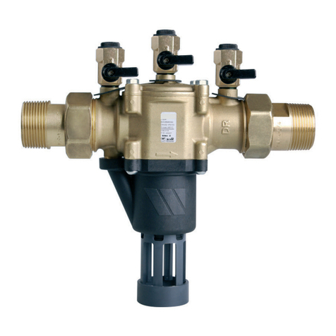
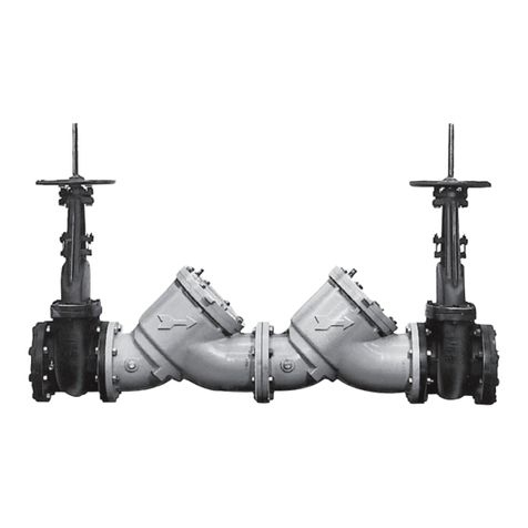
Double Check Valve Assembly
Sizes: 1⁄2" – 2" (15 – 50mm)
You are required to thoroughly read all installation instructions
and product safety information before beginning the installa-
tion of this product. FAILURE TO COMPLY WITH PROPER
INSTALLATION AND MAINTENANCE INSTRUCTIONS
COULD RESULT IN PRODUCT FAILURE WHICH CAN
CAUSE PROPERTY DAMAGE, PERSONAL INJURY AND/
OR DEATH. Watts is not responsible for damages resulting from
improper installation and/or maintenance.
Local building or plumbing codes may require modifications to
the information provided. You are required to consult the local
building and plumbing codes prior to installation. If this informa-
tion is not consistent with local building or plumbing codes, the
local codes should be followed.
Need for Periodic Inspection/Maintenance: This product
must be tested periodically in compliance with local codes, but
at least once per year or more as service conditions warrant.
Corrosive water conditions, and/or unauthorized adjustments
or repair could render the product ineffective for the service in-
tended. Regular checking and cleaning of the product’s internal
components helps assure maximum life and proper product
function.
RP/IS-719
NOTE: For Australia and New Zealand: Pipeline strainers
should be installed between the upstream shutoff valve and the
inlet of the backflow preventer.
Watts product specifications in U.S. customary units and metric
are approximate and are provided for reference only. For precise
measurements, please contact Watts Technical Service. Watts
reserves the right to change or modify product design, construc-
tion, specifications, or materials without prior notice and without
incurring any obligation to make such changes and modifica-
tions on Watts products previously or subsequently sold.
1" 719QT and LF719QT
WARNING
!
Testing
For field testing procedure, send for IS-TK-DP/DL,
IS-TK-9A, IS-TK-99E AND IS-TK-99D.
For other repair kits and service parts, send for PL-RP-BPD.
For technical assistance, contact your local Watts
representative.
Indoors - Figure 1
Check local codes for installation requirements. Pipe lines should
be thoroughly flushed to remove foreign material before installing
the unit. A strainer should be installed as shown, ahead of backflow
preventer to prevent disc from unnecessary fouling. Install valve in
the line with arrow on valve body pointing in the direction of flow.
For indoor installations, it is important that the valve be easily
accessible to facilitate testing and servicing. Do not install in a
concealed location.
CAUTION:
Do not install with strainer when backflow preventer is used on
seldom-used water lines which are called upon during emer-
gencies, such as fire sprinkler lines, etc.
It is important that Series 719 and LF719 be tested periodically
in compliance with local codes but at least once a year or more
often depending upon system conditions. Regular inspection,
testing and cleaning assures maximum life and proper product
function.
NOTE: Fire Protection System Installations
The National Fire Protection Agency (NFPA) Guidelines require
a confirming flow test to be conducted whenever a “main line”
valve such as the shutoff valves or a backflow assembly have
been operated. Certified testers of backflow assemblies must
conduct this test. The trim valves of the confirming flow test
must be closed during the test. When the test is completed,
the trim valves must be returned to a fully open position.
Outside - Figure 2
Parallel - Figure 3
Where approved by code, Watts recommends a custom engi-
neered Watts PVS Series water supply valve station consisting of
two or more 719 and LF719 Series valves piped in parallel to serve
a larger supply main. This type of installation is employed whenever
it is required to maintain water flow to a facility. Typical applications
include hospitals, multi-family dwellings, malls and other similar
applications.
A properly designed Watts PVS valve station provides redundant
flow paths, a continuous supply of adequate water, testing and
servicing of an individual valve without supply interruption, and
long service life.
The size, quantities and design of parallel valve installations should
be exactly in accordance with the engineer’s judgment and the
published Best Practice Guide of Watts Regulator wherever pos-
sible. For a copy of the Watts Best Practice Guide, call Watts at
1-800-617-3274.
2
Installation Instructions
Series 719 and LF719 Double Check Valve Assemblies
719AQT
Meter Box Installation
First Shutoff
Valve
719QT-S Vertical flow-up installation
Strainer
Min. 12"
Fiberglass WattsBox
Now Available, WattsBox Insulated Enclosures.
For more information, send for ES-WB or ES-WB-T.
Figure 2
719QT-S
First
Shutoff Valve
Figure 3
First
Shutoff Valve
719QT-S
Strainer
Figure 1
Service, Replacement Parts and Maintenance
Series 719 and LF719 Double Check Valve Assemblies
Servicing the First and Second Check Valves
NOTE: Before servicing, be certain water is turned off or shutoff
valves are closed
1. Close shutoff valves up and downstream of the valve.
2. Using an appropriate sized wrench, loosen the check valve
cover. Unscrew the check valve cover and lift off.
3. Remove spring.
4. Lift out disc holder assembly from body of valve.
5. To reverse the seat disc, unscrew disc screw and disassem-
ble disc washer and disc rubber from disc holder assembly.
Reverse rubber so opposite face is showing. Assemble disc
screw through disc washer and rubber and screw into disc
holder.
6. To replace seat module, pull out of body by gripping at rein-
forcement ring. Replace seat module with new component by
placing into body seat bore. Tightening cover will engage seat
properly.
7. Insert disc holder assembly back into seat module.
8. Replace spring insuring that it seats properly on disc holder.
9. Place cover onto spring with internal guide on cover posi-
tioned inside end coil.
10. Screw cover onto valve body.
11. Tighten cover wrench tight.
10. Open shutoff valves.
Seat
O-ring
Disc Screw
Reinforcement
Ring
Seat
Disc Washer
Disc Rubber Disc Holder
Cover
Cover
O-Ring
Spring
Body
3
*The wetted surface of this product contacted by consumable
water contains less than 0.25% of lead by weight.
LEAD FREE*
Repair Kits
1⁄2" – 2" (15 – 50mm)
When ordering, specify ordering code number, kit number
and valve size
ORDERING CODE KIT NO. SIZE
in. mm
Total Repair Kits
0889083 RK 719-T 1⁄215mm
0889084 RK 719-T 3⁄420mm
0889085 RK 719-T 1 25mm
0889086 RK 719-T 11⁄4– 11⁄232-40mm
0889087 RK 719-T 2 50mm
Kit consists of: 2 First or Second Check Repair Kits
1st or 2nd Check Kits
0888100 RK 719R10 CK4 1⁄2– 3⁄415-20mm
0889060 RK 719 CK4 1⁄215mm
0889061 RK 719 CK4 3⁄420mm
0889062 RK 719 CK4 1 25mm
0888101 RK 719 CK4 11⁄4– 11⁄232-40mm
0888102 RK 719 CK4 2 50mm
Kit consists of: Disc holder, Spring and Cover O-ring
1st or 2nd Check Rubber Parts Kits
0888103 RK 719R10 RC4 1⁄2– 3⁄415-20mm
0889063 RK 719 RT 1⁄215mm
0889064 RK 719 RT 3⁄420mm
0889065 RK 719 RT 1 25mm
0888104 RK 719 RT 11⁄4– 11⁄232-40mm
0888105 RK 719 RT 2 50mm
Kit consists of: Disc rubber, Seat O-ring and Cover O-ring
1st or 2nd Check Seat Kits
0888997 RK 719R10 S 1⁄2– 3⁄415-20mm
0889069 RK 719 S 1⁄215mm
0889070 RK 719 S 3⁄420mm
0889071 RK 719 S 1 25mm
0888998 RK 719 S 11⁄4– 11⁄232-40mm
0888999 RK 719 S 2 50mm
Kit consists of: Seat, Seat O-ring and Cover O-ring
1st or 2nd Check Cover Kits
0888106 RK 719R10 C 1⁄2– 3⁄415-20mm
0889066 RK 719 C 1⁄215mm
0889067 RK 719 C 3⁄420mm
0889068 RK 719 C 1 25mm
0888107 RK 719 C 11⁄4– 11⁄232-40mm
0888108 RK 719 C 2 50mm
0794039 LFRK 719 C 1⁄215mm
0794040 LFRK 719 C 3⁄420mm
0794041 LFRK 719 C 1 25mm
0794042 LFRK 719 C 11⁄4– 11⁄232-40mm
0794043 LFRK 719 C 2 50mm
Kit consists of: Cover and Cover O-ring.
Note: For 11/4" 719R15 models use 11/4" – 11/2" repair kits.
LEAD FREE*
LEAD FREE*
LEAD FREE*
LEAD FREE*
RP/IS 719 1145 EDP# 1915345 © 2011 Watts
USA: Tel: (978) 688-1811 • Fax: (978) 794-1848 • www.watts.com
Canada: Tel: (905) 332-4090 • Fax: (905) 332-7068 • www.wattscanada.ca
A Watts Water Technologies Company
Limited Warranty: Watts Regulator Co. (the “Company”) warrants each product to be free from defects in material and workmanship under normal usage for a period of one year from the date of
original shipment. In the event of such defects within the warranty period, the Company will, at its option, replace or recondition the product without charge.
THE WARRANTY SET FORTH HEREIN IS GIVEN EXPRESSLY AND IS THE ONLY WARRANTY GIVEN BY THE COMPANY WITH RESPECT TO THE PRODUCT. THE COMPANY MAKES NO OTHER
WARRANTIES, EXPRESS OR IMPLIED. THE COMPANY HEREBY SPECIFICALLY DISCLAIMS ALL OTHER WARRANTIES, EXPRESS OR IMPLIED, INCLUDING BUT NOT LIMITED TO THE IMPLIED
WARRANTIES OF MERCHANTABILITY AND FITNESS FOR A PARTICULAR PURPOSE.
The remedy described in the first paragraph of this warranty shall constitute the sole and exclusive remedy for breach of warranty, and the Company shall not be responsible for any incidental, special
or consequential damages, including without limitation, lost profits or the cost of repairing or replacing other property which is damaged if this product does not work properly, other costs resulting from
labor charges, delays, vandalism, negligence, fouling caused by foreign material, damage from adverse water conditions, chemical, or any other circumstances over which the Company has no control.
This warranty shall be invalidated by any abuse, misuse, misapplication, improper installation or improper maintenance or alteration of the product.
Some States do not allow limitations on how long an implied warranty lasts, and some States do not allow the exclusion or limitation of incidental or consequential damages. Therefore the above
limitations may not apply to you. This Limited Warranty gives you specific legal rights, and you may have other rights that vary from State to State. You should consult applicable state laws to
determine your rights. SO FAR AS IS CONSISTENT WITH APPLICABLE STATE LAW, ANY IMPLIED WARRANTIES THAT MAY NOT BE DISCLAIMED, INCLUDING THE IMPLIED WARRANTIES OF
MERCHANTABILITY AND FITNESS FOR A PARTICULAR PURPOSE, ARE LIMITED IN DURATION TO ONE YEAR FROM THE DATE OF ORIGINAL SHIPMENT.
For additional cross-connection control information, send for F-50 brochure.
Symptom Cause Solution
1. Check valve fails to hold a. Debris on check disc Disassemble and clean
1.0 PSID minimum sealing surface
b. Leaking gate valve Disassemble and clean or repair
c. Damaged seat disc or Disassemble and replace
seat o-ring
d. Damaged guide holding Disassemble clean or replace
check open
e. Weak or broken spring Disassemble and replace spring
2. Chatter during flow a. Worn, damaged or Disassemble and repair or
conditions defective guide replace guide
3. Low flows passing a. Mainline check fouled Disassemble and clean
through mainline
valve
b. Meter strainer plugged Disassemble and clean
c. Damaged mainline seat Disassemble and replace
disc or seat
d. Broken mainline spring Disassemble and replace
Troubleshooting Guide
Series 719 and LF719

This manual suits for next models

1

Other Watts Control Unit manuals

Watts CIVIC1 User manual

Watts

Watts CIVIC1 User manual

Watts SOCLA BA BM User manual

Watts

Watts SOCLA BA BM User manual

Watts 995 Series Setup guide

Watts

Watts 995 Series Setup guide

Watts LFM115-11 Owner's manual

Watts

Watts LFM115-11 Owner's manual

Watts EVO Series User manual

Watts

Watts EVO Series User manual

Watts LFM115-74 Owner's manual

Watts

Watts LFM115-74 Owner's manual

Watts LFM513-5 Series User manual

Watts

Watts LFM513-5 Series User manual

Watts LFM513-14 Series User manual

Watts

Watts LFM513-14 Series User manual

Watts 919 Series Instruction Manual

Watts

Watts 919 Series Instruction Manual

Watts 1170 Series User manual

Watts

Watts 1170 Series User manual

Watts AMES 933GD User manual

Watts

Watts AMES 933GD User manual

Watts 7 Series Instruction Manual

Watts

Watts 7 Series Instruction Manual

Watts 909RPDA User manual

Watts

Watts 909RPDA User manual

Watts AMES 920GD-01-15 User manual

Watts

Watts AMES 920GD-01-15 User manual

Watts bar PMK2 Operational manual

Watts

Watts bar PMK2 Operational manual

Watts 9DS Series User manual

Watts

Watts 9DS Series User manual

Watts LF919 User manual

Watts

Watts LF919 User manual

Watts LFM115-58 Installation and operating instructions

Watts

Watts LFM115-58 Installation and operating instructions

Watts 757 Series Instruction Manual

Watts

Watts 757 Series Instruction Manual

Watts Vision BT-CT02 RF User manual

Watts

Watts Vision BT-CT02 RF User manual

Watts AMES Deringer 40 User manual

Watts

Watts AMES Deringer 40 User manual

Watts LFM127-31 Installation and operating instructions

Watts

Watts LFM127-31 Installation and operating instructions

Watts AMES 979GD User manual

Watts

Watts AMES 979GD User manual

Watts POWERS HydroGuard LFG480 Series User manual

Watts

Watts POWERS HydroGuard LFG480 Series User manual

Popular Control Unit manuals by other brands

Telos Alliance Axia QUASAR XR quick start guide

Telos Alliance

Telos Alliance Axia QUASAR XR quick start guide

M-system R30SV2 instruction manual

M-system

M-system R30SV2 instruction manual

barfield DC400 User instruction

barfield

barfield DC400 User instruction

M-system R30YV4 instruction manual

M-system

M-system R30YV4 instruction manual

Honeywell FY 30 installation instructions

Honeywell

Honeywell FY 30 installation instructions

Carel ir33 Universale user manual

Carel

Carel ir33 Universale user manual

Navkom R7 instruction manual

Navkom

Navkom R7 instruction manual

DoorHan DCUT-1 Original Installation Instructions

DoorHan

DoorHan DCUT-1 Original Installation Instructions

ADLINK Technology Express-SL user manual

ADLINK Technology

ADLINK Technology Express-SL user manual

Phytec phyCORE-STM32MP1 quick start guide

Phytec

Phytec phyCORE-STM32MP1 quick start guide

Controls MVP-M702 product manual

Controls

Controls MVP-M702 product manual

Arbor Technology EmETXe-i2309 Quick installation guide

Arbor Technology

Arbor Technology EmETXe-i2309 Quick installation guide

ETC Eos Remote Processor Unit 3 Setup guide

ETC

ETC Eos Remote Processor Unit 3 Setup guide

BenQ PointWrite PW03 user manual

BenQ

BenQ PointWrite PW03 user manual

Mid-Continent Instrument SAM MD302-3 Installation manual and operating instructions

Mid-Continent Instrument

Mid-Continent Instrument SAM MD302-3 Installation manual and operating instructions

Johnson Controls Penn P28 Series manual

Johnson Controls

Johnson Controls Penn P28 Series manual

DEMA 466P installation instructions

DEMA

DEMA 466P installation instructions

Kohler DTV+ Installation and care guide

Kohler

Kohler DTV+ Installation and care guide

manuals.online logo
manuals.online logoBrands
  • About & Mission
  • Contact us
  • Privacy Policy
  • Terms and Conditions

Copyright 2025 Manuals.Online. All Rights Reserved.