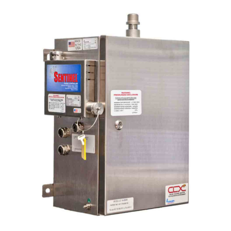
Watts HF scientific SSR-Ex 28037 User manual

Operations and Maintenance Manual
Total Residual Oxidant Monitor for
Use in Hazardous Environments
Model SSR-Ex 28037
IOM-HF-SSR-Ex 28037
WARNING
!
Read this Manual BEFORE using this equipment.
Failure to read and follow all safety and use information can
result in death, serious personal injury, property damage, or
damage to the equipment.
Keep this Manual for future reference.
IOM-HF-SSR-Ex 28037 Rev 5

2
1.0 Safety........................................................................................... 3
1.1 Understanding Safety Information........................................... 3
2.0 Overview ...................................................................................... 3
2.1 Specifications ......................................................................... 4
2.2 Unpacking and Inspection of the Instrument and Accessories .... 5
2.3 Instrument Labels ................................................................... 5
3.0 Components Listing ..................................................................... 5
3.1 Electronics Compartment ....................................................... 5
3.2 Electrical Enclosure................................................................. 5
3.3 User Connections................................................................... 5
3.4 Wet Section of Enclosure Fittings and Items Listing.................... 6
3.5 The Air Sentinel™ II Controller (Factory Installed).................... 6
3.6 The Air Dryer/Filter.................................................................. 6
4.0 Installation .................................................................................... 6
4.1 Mounting and Site Selection ................................................... 6
4.2 Plumbing and Air Connections ............................................... 7
4.3 Electrical Connections ............................................................ 7
4.3.1 Low Voltage Connections .............................................. 8
4.3.1.1 Relays................................................................ 8
4.3.1.2 4-20 mA Analog Output..................................... 8
4.3.1.3 Modbus ............................................................. 8
4.3.1.4 RMT .................................................................. 8
4.3.1.5 Securing the Glands - Low Voltage.................... 8
4.3.2 Mains Power Connections ............................................. 8
4.3.2.1 Securing the Glands - Mains Power................... 8
4.4 Hardware Control ................................................................... 8
4.5 Modbus Control...................................................................... 9
4.6 Securing the Electrical Enclosure.......................................... 10
5.0 Configuration - General Process................................................. 11
5.1 Instrument Commissioning and Start-Up .............................. 11
5.2 Configuring the SSR-EX ....................................................... 11
5.2.1 Menu Selection Options............................................... 12
5.2.1.1 Main Menu....................................................... 12
5.2.1.2 Config Menu .................................................... 12
5.2.1.3 Analog Output Menu........................................ 13
5.2.1.4 Modbus Menu ................................................. 13
5.2.1.5 Alarms Menu.................................................... 13
5.2.1.6 Units Menu ...................................................... 13
5.2.1.7 Average Menu.................................................. 13
5.2.1.8 Backlight Menu................................................ 13
5.2.1.9 Cycle Time Menu ............................................. 14
5.2.1.10 Contact Period Menu..................................... 14
5.2.1.11 Standby Pulse Menu...................................... 14
5.2.1.12 Restore Defaults Menu................................... 14
5.2.1.13 Restore Factory Cal Menu ............................. 14
5.2.1.14 About Device Menu ....................................... 14
5.3 System Start-Up................................................................... 15
5.3.1 Flush Water Sample Line ............................................. 15
5.3.2 Prepare Reagents ........................................................ 15
5.3.3 Remote Start ............................................................... 15
5.4 Typical Cycle......................................................................... 15
5.5 Observe Operation ............................................................... 15
6.0 Maintenance............................................................................... 15
6.1 Calibration ............................................................................ 15
6.2 Cuvette Replacement ........................................................... 16
6.3 T-Strainer Cleaning ............................................................... 16
6.4 Adjusting the Pressure Regulator.......................................... 16
6.5 Installing New Reagent in the SSR-EX.................................. 16
6.6 Replacing the Peristaltic Sample Pump Head....................... 16
6.7 Instrument Storage ............................................................... 16
7.0 Diagnostic/Troubleshooting Chart............................................... 17
8.0 Error/Alarm Messages and Suggested Actions .......................... 17
9.0 Technical and Customer Assistance ........................................... 17
10.0 Spare Parts Listing ................................................................... 17
11.0 Limited Warranty ...................................................................... 20
Table of Figures
Figure 1 - Instrument Overview........................................................... 3
Figure 2 - Instrument with Electronics Compartment Open ................ 5
Figure 3 - Close-up of Electrical Compartment................................... 5
Figure 4 - Low Voltage Connections................................................... 5
Figure 5 - Wet Chemistry Area of Enclosure ....................................... 6
Figure 6 - Utility Connections.............................................................. 6
Figure 7 - Air/Dryer Filter .................................................................... 6
Figure 8 - Overall Mounting Dimensions of the Instrument.................. 6
Figure 9 - Compression Fitting ........................................................... 7
Figure 10 - Utility Connections............................................................ 7
Figure 11 - Low Voltage Connections................................................. 8
Figure 12 - Main Screen ................................................................... 11
Figure 13 - Pressure regulator and T-strainer.................................... 15
Table of Contents

3
1.1 Understanding Safety Information
This manual contains safety and use instructions that must be
followed during the installation, commissioning, operation, care and
maintenance, and service of the SSR-Ex. All responsible personnel
must read this manual prior to working with this instrument and should
familiarize themselves with the following safety symbols, signals,
and pictorials.
The safety alert symbol is shown alone or used with a signal word
(DANGER, WARNING or CAUTION), a pictorial and/ or a safety
message to alert you to hazards.
When you see this symbol alone or with a signal word on this
instrument or in this manual, be alert to the potential for death or
serious personal injury.
Safety signal words have the following meaning:
Identifies hazards which, if not avoided, could
result in death or serious injury.
Identifies hazards which, if not avoided, will
result in minor or moderate injury.
Identifies practices, actions or failure to act
which will result in property damage or damage
to the equipment.
Pictorials used on the equipment and in this Manual have the following
meanings:
This pictorial alerts you to the need to read the
Manual.
This pictorial alerts you to electricity,
electrocution and shock hazards.
1.0 Safety 2.0 Overview
This instrument has been specifically designed for TRO measurement
and to operate in hazardous atmospheres meeting the IECEx and ATEX
ratings as stated in the specifications. The instrument uses an IECEx
approved purge/ pressurization controller called the Air Sentinel II.
Please refer to the companion manual Cat. No. 100038B for all
information on:
• Operation of the Air Sentinel II
• Electrical Power Connections
• Purge Air Connection
Figure 1 - Instrument Overview
This instrument is sectioned such that all the electrical or powered
devices are in the upper, purged section of the enclosure, while
the lower (wetted parts) section contains no power at all and can
be operated and maintained in a safe condition even with the main
enclosure door open. Refer to Figure 2.
The SSR-Ex has been designed to meet the design criteria specified
by Standard Methods for the Examination of Water and Wastewater
(21th Edition) Method 4500-Cl G. DPD Colorimetric Method.
The SSR-Ex uses a 515nm LED as the measurement light source.
Every effort has been made to ensure the accuracy of this manual. Due
to the continuous development and improvement of all instrumentation,
there may be slight differences between this manual and the instrument
received.

4
2.1 Specifications
Measurement Range 0.00 – 15.00 mg/l (PPM)
Accuracy ±10% of reading or ±0.03 mg/l (PPM)
whichever is greater for range of 0 - 15.0 mg/l (PPM)
Resolution 0.01 mg/l (PPM)
Cycle Time Adjustable; 45 seconds to 10 minutes (600 seconds)
Display 3.5" Color Graphic
Alarms Two programmable, 120 - 240 VAC 2A, Form C Relay
Analog Output Powered 4 - 20 mA, 1000Ω drive, isolated
Communications Port Bi-directional RS-485 with Modbus
Water Pressure Integral pressure regulator, maximum pressure 3 bar (45 PSI.)
Flow Rate to Waste Maximum waste flow rate from the drain is 150 ml/min
Operating Temperature 0°C – 55°C (32°F – 131°F)
Wetted Materials Polyethylene, Borosilicate Glass, Generic Viton™* Alternative (FKM), Polypropylene, 316 Stainless Steel, Acetal, EPDM, Silicone, Modified
PPO, Thermoplastic Elastomer
Sample Temperature Range 0°C – 55°C (32°F – 131°F)
Power Supply 100 to 230VAC, 47 - 63 Hz, 240VA
Insulation Rating Double Insulated, Pollution Degree 2, Overvoltage Category II
Enclosure Powder coated steel with windows. IP55 rating
Environmental Conditions Altitude up to 2000 meters
Up to 95% RH (non-condensing)
IECEx Hazloc Rating II 2G Ex pxb IIC T4 Gb 0°C ≤ Ta ≤ 55°C
Compressed Air Requirements Water and oil-free, Particles <5u, ISA Grade Hydrocarbon Free. Full time clean dry air at 5.5 - 7 bar (80 - 101.5 PSI) @ 35 SLPM
(1.2 SCFM) @ 20oC (68oF) Max
Regulatory Compliance And Certifications IECEx, ATEX, DNVGL-CG-0339, tested to USCG 46 CFR Part 162
subsection 162.060-30
Shipping Weight 27.2 kg (60 lbs.)
Shipping Dimensions 93 cm X 62 cm X 32 cm (36½" X 24½" X 12½")
*Viton™ is a trademark of The Chemours Company FC, LLC

5
2.2 Unpacking and Inspection of the
Instrument and Accessories
The table below indicates the items included in the shipment.
Item Quantity
SSR-Ex Monitor Includes - Factory installed Air Sentinel II 1
Owner’s Manual 1
Air/Filter Dryer Assembly 1
*Please note: Reagents are not included and must be purchased
separately. The SSR-Ex will not function without reagent.
Remove the instrument from the shipping crate. Carefully inspect all
items to ensure that no visible damage has occurred during shipment.
If damage is evident contact the delivery company and your supplier. If
the items received do not match the order, please immediately contact
the local distributor or the HF scientific Customer Service Department.
Location Location Label
Serial number,
manufacturer, part
number, power
rating, CE & UL
marking
Side of Unit
Warning and
informational
Inside Front of
Electrical Panel
Enclosure
Warning and
informational
Front of Unit
Informational Front of Unit
2.3 Instrument Labels
The following labels should be applied to the outside of the enclosure.
3.0 Components Listing
3.1 Electronics Compartment
WETTED COMPONENTS COMPARTMENT
ACCESSIBLE ANY TIME
CONTAINS REAGENT BOTTLES
OPTICAL MEASUREMENT COMPONENTS
INLET WATER SAMPLE PUMP (PERISTALTIC)
CONNECTIONS FOR PURGE AIR, DRAIN AND SAMPLE
WATER INLET. ALSO, EMERGENCY DRAIN FITTING
T-STRAINER AND
PRESSURE REGULATOR
ELECTRONICS COMPARTMENT
(AIR PURGED WHEN SCREWED CLOSED)
SHOWN OPEN TO ALLOW CONNECTIONS
AIR SENTINEL II
(FACTORY
INSTALLED)
Figure 2 - Instrument with Electronics Compartment Open
3.2 Electrical Enclosure
3.3 User Connections
Figure 3 - Close-up of Electrical Compartment
Figure 4 - Low Voltage Connection
PURGE AIR PRESSURE REGULATOR
CABLE GLANDS
FOR LOW VOLTAGE
CONNECTIONS
CONNECTORS FOR LOW VOLTAGE
CONNECTIONS (see below for detail)
MAINS
POWER INTO
ENCLOSURE
REAGENT
PUMPS
User Connections for SSR-Ex
RELAYS
4-20 mA
RMT CONNECTIONS

6
3.4 Wet Section of Enclosure Fittings and
Items Listing
Ai r
Dr ai n
Sa mp l e
Optical Assembly Plumbing Connections
Figure 5 - Wet Chemistry Area of Enclosure
EMERGENCY DRAIN (NO CONNECTION
NEEDED)
SAMPLE WATER (6mm connection)
MAIN DRAIN (12 mm connection)
PURGE AIR (AIR ONLY 6mm connection)
DO NOT MIX UP THE AIR and WATER
CONNECTIONS. INSTALLING THE WATER
INTO THE AIR CONNECTION WILL VOID
THE WARRANTY.
Figure 6 - Utility Connections
Reagent Optical
Bottles Assembly
3.5 The Air Sentinel II Controller
(Factory Installed)
The SSR-Ex will not function without proper air purging of the
enclosure. The Air Sentinel II Controller governs the power. Reference
Section 2.1Electronics Compartment, Figure 2 - Instrument with
Electronics Compartment Open.
3.6 The Air Dryer/Filter
For proper operation dry clean air must be supplied to the SSR-Ex at
pressures between 5.5 and 7 bar (80 to 101.5 PSI). The dryer comes
with fittings suitable for use with 6mm tubing, if using the supplied
fittings for installation ensure that a proper thread sealant is used.
Element Replacement
Indicator The red ring
will pop up to show
when the element
needs to be replaced.
Figure 7 - Air/Dryer Filter
4.0 Installation
4.1 Mounting and Site Selection
The instrument is designed for wall mounting. Choose a location that is
easily accessible for operation and service. It is recommended that the
display window is about eye level. Consideration must be made for the
plumbing, air, and electrical conduit connections. The overall mounting
dimensions of the instrument are shown in Figure 8 - Overall Mounting
Dimensions of the Instrument.
Figure 8 - Overall Mounting Dimensions of the Instrument
Be sure that the instrument is mounted as close as possible to the
sampling point to ensure a quick response time (recommended
installation is within 2-3 meters (6-10 ft) of the sampling point).
Mounting bolt size should not exceed the size of provided mounting
bolt location. Mounting hardware must be rated to support the
instrument operation weight of 60 lbs. Mounting hardware provided
by others.

7
4.2 Plumbing and Air Connections
To avoid injury, death, fire, explosion, leak, or property damage:
• The fluid waste from the drain connection MUST NEVER
BE reintroduced into the incoming water stream. HF
scientific recommends that operators review with local
authorities concerning the proper disposal of waste
diluted fluids.
• All plumbing connections MUST BE made through the
provided stainless steel connections. Fittings should not
be modified or substituted.
• The air line and the water line MUST NOT BE reversed
in connecting the supplies. Connecting the water source
to the air line will damage the electronics and void
the warranty.
• All connections MUST BE properly installed and sealed
to ensure water tightness and preserve the ratings of
the instrument.
• The drain MUST BE open to the atmosphere for proper
operation. Ensure the vent drain remains open and is not
subject to fouling.
All wet and air connections are made with user supplied tubing using
the compression fittings attached to the SSR-Ex. When using the
compression fittings, follow these steps:
Step 1: Unscrew the nut from the applicable connection point.
Step 2: Remove the nut, front sleeve, and back sleeve from the
SSR-Ex.
Step 3: Place the nut, then the back sleeve, and then the front sleeve
onto the applicable tubing.
Step 4: Slide the tubing into the open connection point and
tighten the nut to secure the tubing. Refer to Figure 9.
Fitting Connections for assistance to assemble the tubing
connection. Refer to Figure 10 - Utility Connections for
assistance locating the proper fitting connection on the
enclosure for the sample to be connected.
Figure 9 - Compression Fitting
When making the plumbing connections, be advised that:
• The maximum pressure for proper operation is 3 bar (45 PSI).
• The maximum sample water intake and drainage flow is
150 ml/minute.
• The maximum allowable fluid temperature is 55°C (131°F).
• The sample water supply does not need to be pressurized.
The SSR-Ex incorporates a pressure regulator at the water
supply inlet.
• In order to ensure that the sample measured is representative of
the ballast water, keep sample pipe runs as short as possible.
• A water shut off valve should be located close to the instrument
to allow for periodic maintenance.
• An air shut off valve should be located close to the instrument to
allow for periodic maintenance.
EMERGENCY DRAIN (NO CONNECTION
NEEDED)
SAMPLE WATER (6mm connection)
MAIN DRAIN (12 mm connection)
PURGE AIR (AIR ONLY 6mm
connection)
NOTE: IMAGE DEPICTS BOTTOM OF
THE ENCLOSURE.
DO NOT MIX UP THE AIR and WATER
CONNECTIONS. INSTALLING THE
WATER INTO THE AIR CONNECTION
WILL VOID THE WARRANTY.
Figure 10 - Utility Connections
All wet and air connections are made with user supplied OD tubing
using the compression fittings attached to the SSR-Ex. All air and water
tubing connected to the instrument is to be supplied by others. When
using the compression fittings, see Figure 9 - Compression Fitting and
then follow these steps:
Do not connect sample water line to the purge air connection.
Plumbing Connections
Step 1: Connect the sample water line to the SSR-Ex using the 6 mm
OD fitting on the bottom of the enclosure. Reference Figure
10 - Utility Connections.
Step 2: Connect the main drain line to the SSR-Ex using the 12 mm
OD fitting on the bottom of the enclosure.
Reference Figure 10 - Utility Connections. There is no tubing
connection for the emergency drain.
Air Connection
Step 1: Install the air/filter dryer assembly by mounting it in
a convenient location near the SSR-Ex between the
compressed air supply and the SSR-Ex.
Step 2: Connect the compressed air supply to the air/filter dryer
assembly intake.
Step 3: Connect the air supply tubing from the air/filter dryer
assembly output to the SSR-Ex using the 6 mm OD fitting
on the bottom of the enclosure. Reference Figure 10 - Utility
Connections.
4.3 Electrical Connections
The power must be provided by a safe remote location. All
power must be removed from a safe location while the electrical
compartment access is open. Do not reconnect power until the
electrical compartment access is closed and all captive Philips
screws have been replaced and tightened appropriately.
All electrical connections are located in the upper electrical
compartment. The electrical compartment access at the front
can and should only be opened during installation. No power
should be applied until the electrical compartment access is
closed and sealed.
The SSR-Ex has two types of electrical connections. First, the mains
power connection, which connects to the Air Sentinel II through the
cable gland on the left side of the SSR-Ex. Second, the low voltage
connections, which are made through the cable glands on the right
side of the SSR-Ex.

8
All low voltage connections should be completed before the
main power is connected to system.
All electrical connections must pass through a compression
gland. The glands can accept cabling from 11 to 21 mm in
diameter. After installation, the glands must be tightened to
ensure that the SSR-Ex maintains cabinet air pressure.
Mains power connects only to the Air Sentinel II.
No mains power should be connected directly to the main PCB.
Figure 11 - Low Voltage Connections
User Connections for SSR-Ex
RELAYS
4-20 mA
RMT CONNECTIONS
4.3.1 Low Voltage Connections
All of the low voltage electrical communication connections to the
instrument are made at the termination area located on the right side
of the main PCB. To access the connections, lower the access flap by
loosening the captive Phillips screws. The connections are labeled and
are self-descriptive. Please follow all government recommendations and
requirements for installation of electrical connections to and between
the instrument and other peripheral devices. All terminals are designed
to accept wires in the range of 14 - 28 AWG.
4.3.1.1 Relays
Two relay alarm connections labeled COM1, NC1 & NO1 and COM2,
NC2 & NO2 are provided. The relays are rated 240VAC 2A. Operation
of this alarm is covered in section 4.2.1.5 Alarms Menu.
4.3.1.2 4 - 20 mA Analog Output
These connections are located on the mid right side of the Main PCB.
The 4 - 20 mA output is driven by a 24 VDC power source and can
drive recorder loads up to 1000 ohms. Transformer isolation is provided
on the SSR-Ex. Operation of this output is covered in section 4.2.1.3 -
Analog Output Menu.
Polarities of the connections are labeled beside this termination on the
PC board.
The recommended cable is 22 AWG shielded twisted pair. To prevent
ground loops, connect the shield at its destination. The terminal block
is removable to assist in making connections.
The 4 - 20mA is factory calibrated. An adjustment is available on the
4 - 20mA in section 4.2.1.3 Analog Output Menu. In addition to making
adjustments, these menus output continuous 4 mA or 20 mA and
can be used as a signal test. The configuration mode will timeout
after 15 minutes.
4.3.1.3 Modbus
The RS-485 half-duplex (2-wire) digital interface operates with
differential levels that are not susceptible to electrical interferences.
Therefore, cable lengths up to 3000 ft can be implemented. The last
device on every bus may require a 120-ohm termination resistor to
eliminate the possibilities of signal reflection on the line. Do not run RS-
485 cables in the same conduit as power.
Ensure each instrument is not powered when connecting the RS-
485 line. To prevent damage to the instrument, ensure that power is
disconnected prior to making connections. The Modbus connection is
located on the lower right portion the main PCB as seen on Figure 11.
4.3.1.4 RMT
By design the SSR-Ex will only be actuated for measurement by a
remote command. The system can be set up to either be actuated
through MODBUS or by means of a remote actuation provided by the
end user.
These connections are located in the lower right corner of the main
PCB. See Figure 4 - Low Voltage Connections.
The instrument operates on user control software, where an external
control initiates each cycle. The SSR-Ex will indicate the current status
of connections using a relay contact that is closed when busy and
open when in standby mode.
4.3.1.5 Securing the Glands - Low Voltage
Low voltage connections to the instrument are made through electrical
glands located on the right side of the enclosure. Once the appropriate
low voltage wiring is inserted through the electrical gland and wiring
is secured at the terminals on the main circuit board glands on the
right side of the enclosure must be tightened to ensure wiring is
safely installed.
4.3.2 Mains Power Connections
Once all low voltage connections are made, the mains power should be
connected through the Air Sentinel II. Reference Figure 3 – Close-up of
Electrical Compartment.
4.3.2.1 Securing the Glands - Mains Power
Mains power connection to the instrument is made through an electrical
gland located on the left side of the enclosure. Once the mains power
wiring is inserted through the electrical gland and wiring is secured at
the mains power terminals of the Air Sentinel II electrical gland on the
left side of the enclosure must be tightened to ensure mains power
wiring is safely installed.
4.4 Hardware Control
The connections are labeled RMT Stby. The input has + and – polarity
connections and requires an external 24VDC control signal.
The output is simply a relay contact and is not polarized. After the
SSR-Ex completes a cycle of measurement, the unit will return to
standby awaiting another pulsed signal to measure. Alternately, 24VDC
can be continuously applied and the SSR-Ex will take readings until
the 24VDC is removed. When power is removed it will complete the
current cycle. The measured value will remain displayed until the
next measurement.

9
4.5 Modbus Control
In addition to the above mentioned Remote Standby Connections,
control can also be achieved using Modbus control. Two special
Modbus addresses are provided. The reading cycle is initiated using
the Coil Address 00005 with the default at False (0). Setting this
Address to True (1) initiates the reading cycle.
At any time the standby status can be checked at Modbus Coil
Address 00005 or Modbus Input Address 10005. False (0) indicates
standby and True (1) indicates the measurement cycle is taking place.
Control is only available from the Coil Address 00005 for more setting
information refer to Section 4.2.1.4. - Modbus Menu.
The default communication parameters are 8 bits, no parity and 1 stop
bit. Please note that all Modbus communication is via RS-485. The
instruments can support a two wire multidrop network of 255 units. If
the connection is to the master on USB, an RS-485 to USB converter
is required.
4.5.1 Coils
These single-bit values are readable and changeable from the master.
The data will be returned with the lowest addressed coil in the least
significant bit (LSB) of the data. Unused bits in the data will be set to 0.
True is a 1 and False is 0.
4.5.1.1 Valid Command(s)
Code Name Broadcast
0x01 Read Coil Status No
0X05 Force Single Coil Yes
MSB LSB
Bit 15 Bit 14 Bit 13 Bit 12 Bit 11 Bit 10 Bit 9 Bit 8 Bit 7 Bit 6 Bit 5 Bit 4 Bit 3 Bit 2 Bit 1 Bit 0
4.5.1.2 Format
16-bit word format
4.5.1.3 Valid Addresses
00001 – 00XXX
4.5.1.4 Definitions
Address Function Default
00001 NOT USED False
00002 NOT USED False
00003 NOT USED False
00004 Service mode (Go into service mode if true) False
00005 FDI (flag data in)
False means waiting for a command. Standby mode. True means
start a cycle.
False
00006 Zero Flag – Zero the reading if True False
00007 Prime mode – Start a prime if True False
4.5.2 Input Status
These single-bit values are readable from the master. The data will be
returned with the lowest addressed input status in the least significant
bit (LSB) of the data. Unused bits in the data will be set to 0.
4.5.2.1 Valid Command(s)
Code Name Broadcast
0x02 Read Input Status No
4.5.2.2 Format
16-bit word format
MSB LSB
Bit 15 Bit 14 Bit 13 Bit 12 Bit 11 Bit 10 Bit 9 Bit 8 Bit 7 Bit 6 Bit 5 Bit 4 Bit 3 Bit 2 Bit 1 Bit 0
4.5.2.3 Valid Addresses
10001 – 10XXX
4.5.2.4 Definitions
Address Function Default
10001 Instrument error False
10002 Instrument error with alarm False
10003 Alarm 1 active False
10004 Alarm 2 active False
10005 FDO (flag for data out)
False means waiting for a command to start. True means
going through a cycle (busy).
False
4.5.3 Holding Registers
These 16-bit values are readable and changeable from the master. The
data is stored and transmitted with the most significant bit (MSB) first
and then the least significant bit (LSB).
4.5.3.1 Valid Command(s)
Code Name Broadcast
0x03 Read Holding Registers No
0x06 Preset Single Register Yes
0X16 Preset Multiple Registers Yes
4.5.3.2 Format
Float – stored in two consecutive addresses, with the first address
containing the least significant word (lower part of mantissa) and the
second address containing the most significant word (sign, exponent,
and upper part of mantissa).
4.5.3.3 Valid Addresses
40001 – 40XXX
4.5.3.4 Definitions
Address Type Register Min Default Max Function
40001 Int NOT USED 0 0 0
40002 Int Units (scaling) 0 0 1 0 – PPM
1 – MG/L
40003 Int Readings Per Average 1 2 5 Number of readings
used for averaging
40004 Int LCD backlight 10 80 100 Percent. Higher is
brighter
40005, 40006 Float 4-20 mA minimum
value
0.0 0.00 15.0 Scaling value
40007, 40008 Float 4-20 mA maximum
value
0.0 15.00 15.0 Scaling value
40009 Int 4-20 mA error alarm
output
0 2 3 0 – Off
1 – 0 mA
2 – 2 mA
3 – 4 mA

10
Address Type Register Min Default Max Function
40010 Int RS-485 baud 0 3 4 0 – 1,200
1 – 2,400
2 – 4,800
3 – 9,600
4 – 19,200
40011 Int NOT USED 0 0 0
40012 Int RS-485 parity 0 0 2 0 – None
1 – Even
2 – Odd
40013 Int RS-485 stop bits 0 1 1 0 – One
1 – Two
40014 Int Instrument
address
1 1 255 Slave address
40015 Int Modbus serial
mode
0 0 1 0 – RTU
1 – ASCII
40016 Int Alarm 1 type 0 0 3 0 – Off
1 – Low alarm
2 – High alarm
3 – Error alarm
40017,
40018
Float Alarm 1 set point 0.0 0.0 15.0
40019 Int Alarm 2 type 0 0 3 0 – Off
1 – Low alarm
2 – High alarm
3 – Error alarm
40020,
40021
Float Alarm 2 set point 0.0 0.0 15.0
40022 Int Not used 0 0 0 Not used
40023 Int Contact time 0 0 600 Seconds before starting
measurements (steps of
15sec.)
40024 Int Measurement
period
45 45 600 Seconds for measurements
to complete
40025 Int Standby purge 0 24 100 Hours between pulsing of
reagent pumps (0 = OFF,
no pulsing)
4.5.4 Input Registers
These 16-bit values are readable by the master. The data is stored
with the most significant bit (MSB) first and then the least significant
bit (LSB).
4.5.4.1 Valid Command(s)
Code Name Broadcast
0x04 Read Input Registers No
4.5.4.2 Format
Float – stored in two consecutive addresses, with the first address
containing the least significant word (lower part of mantissa) and the
second address containing the most significant word (sign, exponent,
and upper part of mantissa).
4.5.4.3 Valid Addresses
30001 – 30XXX
Address Type Register Function
30001,
30002
Float Sensor read-
ing
The meter reading
30003,
30004
Float ABS The absorbance
30005 Int Main version Main board software version
30006 Int Display
version
Display board software version
30007 Int NOT USED
30008 Int Model number 28037
30009 Int Model suffix
number
Options – model dependent 0
30010 Int Reading
status
0 – unknown
1 – normal
2 – over range
3 – under range
4 – need standard
5 – need sample
6 – reading problem (Reading error)
Above will display last reading twice
then 0.00 is displayed.
30011 Int NOT USED
30012 Int Instrument
error summary
(bit-mapped)
0x00000 – normal
0x00001 – Error
0x00002 – Alarm 1 is active
0x00004 – Alarm 2 is active
0x00008 – Calibration error
0x00010 – Optical error
0x00020 – 12-volt power supply
(Fatal error) 0x00040 – Purge solenoid
0x00080 – Reagent solenoid
(Halting error)
0x00100 – STM32 internal A/D
converter (Fatal error)
0x00200 – STM32 flash data read
(Fatal error)
0x00400 – STM32 flash data write
(Fatal error) 0x00800 – LTC2400 A/D
problem (Fatal error)
4.5.5 Exception Responses Implemented
Code Name Meaning
00 -- No error
01 ILLEGAL FUNCTION The function code is not allowed in
the device.
02 ILLEGAL DATA
ADDRESS
The data address is not allowed in
the device
03 ILLEGAL DATA
VALUE
A value contained in the query field is
wrong for the device
4.6 Securing the Electrical Enclosure
Once all electrical connections are made, the electrical enclosure must
be secured by closing the compartment and tightening the captive
Phillips screws.
4.5.4.4 Definitions

11
4.5.5 Exception Responses Implemented
5.0 Configuration - General
Process
5.1 Instrument Commissioning and
Start-up
After all water, air, and electrical connections have been made, the
SSR-Ex can be powered on by turning on the power to the Air Sentinel
II. Once power is supplied to the Air Sentinel II, it will run through an
automatic three-minute purge cycle and then supply power to the
SSR-Ex. If at any time there is a loss of pressurization in the electrical
enclosure, the Air Sentinel II will remove power to the SSR-Ex.
The condition of the Air Sentinel II can be determined based on the
color of the LED lamps on its body as explained by this chart:
Lamp Color Matrix Meaning Power to
Attached
Device
Alarm Relay
Response
Both Lamps
GREEN
Safe
Operation
ON Normally Open
Contacts OPEN
TIMER Lamp RED Instrument
is Purging
OFF Normally Open
Contacts
CLOSE
PRESSURE Lamp
RED
Unsafe
Operation
OFF Normally Open
Contacts
CLOSE
NO Lamps No power
out applied
No power
applied;
everything
off
The SSR-Ex is ready for operation when the Air Sentinel II displays two
green LED lamps.
5.2 Configuring the SSR-Ex
The SSR-Ex is configured using the buttons located on the outside of
the electrical enclosure. The Mainscreen is shown below in Figure 12 -
Main Screen.
Using the UP and DOWN buttons, navigate to the desired function
shown on the screen. Once you have highlighted the desired function
press
SELECT to display the next menu.
The Service and Config menus permit access to the processes listed in
the charts below. Use the EXIT button to return to the previous screen.
Figure 12 - Main Screen
Service Menu Options
Config Menu Options
Title Function/Description
PRIME Prime DPD and Buffer Reagents.
CALIBRATE Initiate Calibration Procedure. Follow
prompts to complete.
WATER PRIME Actuate the sample pump to flush the
water lines.
Title Function/Description
ANALOG OUTPUT Configure 4 - 20 mA Output
MODBUS Configure MODBUS
ALARMS Configure Alarms
UNITS Select PPM or mg/l
AVERAGE Select Signal Averaging 1 - 5 cycles
BACKLIGHT Adjust Display Backlighting
CYCLE TIME Reading Update Rate
CONTACT PERIOD Permits Chlorine Contact time before
measuring
STANDBY PULSE Pulses reagent to reduce clogging
while in standby
RESTORE DEFAULTS Restores factory default settings
RESTORE FACTORY CAL. Restore factory calibrations
ABOUT DEVICE Displays the DISPLAY and MAIN
software version numbers

12
5.2.1 Menu Selection Options
5.2.1.1 Main Menu
SERVICE MENU By design the SSR-Ex will only be actuated for
measurement by a remote command. The system can be set up
to either be actuated through MODBUS or by means of a remote
actuation provided by the end user.
PRIME function pulses the reagent pumps to ensure the reagent lines
are filled with reagent.
CALIBRATE function allows you to calibrate the SSR-Ex in the field.
Please refer to Section 5.1 - Calibration for the calibration procedure.
WATER PRIME function allows the sample pump to be actuated to
flush the water line to the SSR-Ex in order to expedite delivery of
representative sample to the SSR-Ex.
Every time SERVICE mode is exited, all faults are cleared. If the original
fault or a new fault occurs, it will be posted to the display. Faults will not
stay cleared until the fault condition is no longer detected.
(Select using UP & DOWN buttons)
HOME No Change
PRIME
CALIBRATE
WATER PRIME
(SEE BELOW)
CONFIG
ANALOG OUTPUT (see 4.2.1.3)
CONFIG
MODBUS (see 4.2.1.4)
ALARMS (see 4.2.1.5)
UNITS (see 4.2.1.6)
AVERAGE (see 4.2.1.7)
BACKLIGHT (see 4.2.1.8)
CYCLE TIME (see 4.2.1.9)
CONTACT PERIOD (see 4.2.1.10)
STANDBY PULSE (see 4.2.1.11)
RESTORE DEFAULTS (see 4.2.1.12)
RESTORE FACTORY CAL
ABOUT DEVICE
(see 4.2.1.13)
(see 4.2.1.14)
SERVICE
PRESS SELECT TO
ACCESS
Once changes have been made to the settings, the SSR-Ex will display
the prompt “Are you sure?” To save the changed settings, press the
SELECT button.
5.2.1.2 Config Menu

13
5.2.1.3 Analog Output Menu
Select using UP & DOWN buttons)
SSR-Ex allows the user to determine how an error message will affect
the analog outputs. Settings include driving the analog output either
to 0 mA, 2 mA, or 4 mA or the setting can be OFF to not affect the
output.
Default value is OFF.
SSR-Ex allows the analog output to be scaled to the desired range
using the 4 mA and 20 mA adjustments. Select either 4 mA or 20 mA
and using the UP & DOWN buttons adjust to the desired value.
Default values are 4 mA = 0 ppm and 20 mA = 15 ppm
The 4 and 20 mA outputs can be offset to account for signal loss
between the SSR-Ex and the SCADA system using the 4 mA and 20
mA CALIBRATE options.
ERROR LEVEL
MODE
ALARM 1 TYPE
4 mA
BAUD RATE
ALARM 1 SETPOINT
20 mA
ADDRESS
ALARM 2 TYPE
4 mA CALIBRATE
PARITY
ALARM 2 SETPOINT
20 mA CALIBRATE
STOP BITS
ANALOG OUTPUT
MODBUS
ALARMS
5.2.1.4 Modbus Menu
5.2.1.5 Alarms Menu
The factory default setting is 9600, 8 bit, no parity, 1 stop bit, RTU. All
parameters are adjustable. Make sure the parameters on the Host and
the SSR-Ex are configured identically.
(Select using UP & DOWN buttons)
These settings allow the user to configure the SSR-Ex MODBUS.
Settings include the MODE, BAUD RATE, ADDRESS, PARITY and
BITS.
(Select using UP & DOWN buttons)
SSR-Ex allows the alarms to be configured to be either HI, LO, OFF or
ERROR and the set points can be configured to actuate the relays at
the desired values.
ppm
mg/l
UNITS
(Select using UP & DOWN buttons)
SSR-Ex will display units in either ppm or mg/l. Default value is ppm.
(Select using UP & DOWN buttons)
SSR-Ex averages the selected number of readings and displays the
average on the display MODBUS and on the analog output.
Default value is 2.
(Select using UP & DOWN buttons) Change is in increments of 10.
Default value is 80%.
5.2.1.8 Backlight Menu
5.2.1.7 Average Menu
5.2.1.6 Units Menu
AVERAGE 1 - 5
% RANGE 10% - 100%

14
(Select using UP & DOWN buttons) Values are in seconds.
Default value is 45 seconds.
The SSR-Ex will perform a test based on the cycle time interval
selected and actuation by means of MODBUS or RST.
(Select using UP & DOWN buttons)
The range 0:00 to 10:00 in minutes and seconds. The default is 00:00
This setting enables the user to allow contact time with the ballast
water and selected oxidant.
5.2.1.10 Contact Period Men
5.2.1.9 Cycle Time Menu
45 - 600CYCLE TIME
0:00
CONTACT PERIOD
OFF - 100
STANDBY PULSE
(Select using UP & DOWN buttons)
This setting will energize the reagent pumps to ensure the lines remain
free of clogs. Range of settings is 1 - 100 hours. Setting below 1 turns
the function OFF.
Default setting is ON and default time is 24 Hr.
This option will restore the factory default settings. Screen displays
“RESET DEFAULTS?” Pressing the SELECT button will restore factory
default settings. Before performing a Restore Defaults it is advised to
make a listing of any user changed menu options prior to the reset.
5.2.1.12 Restore Defaults Menu
5.2.1.11 Standby Pulse Menu
RESTORE DEFAULTS RESET DEFAULTS?
This option will restore the factory default calibration. Screen displays
“RESTORE FACTORY CAL?” Pressing the SELECT button will restore
the factory calibration. This will restore the factory reading, 4 and 20mA
calibrations.
5.2.1.13 Restore Factory Cal Menu
RESTORE FACTORY CAL RESTORE FACTORY CAL?
(Select using UP & DOWN buttons)
This option will display the DISPLAY and MAIN software version
numbers.
5.2.1.14 About Devise Menu
DISPLAY: VERSION XX MAIN: VERSION:
XX
ABOUT DEVICE

15
5.2.1.13 Restore Factory Cal Menu 5.3 System Start-up
Once the SSR-Ex is powered on, air has been purged, and all
configurations have been completed, it is ready for use.
5.3.1 Flush Water Sample Line
Before sampling any sample water, the water line from the source
water to the enclosure must be flushed to ensure that the sample line
has a representative sample and is not impacted by any debris or other
foulants. Flush the sample line by using the WATER PRIME feature
found under the SERVICE menu. When this feature is selected, the
connect- ed water sample line will automatically flush water to drain.
Reference section 4.2.1.1 main menu.
5.3.2 Prepare Reagents
Prepare and install the reagents according to the instructions provided
on the reagent bottles. In the SERVICE menu, select PRIME to prime
the reagents. You can access the bottom of the enclosure to service
these items, if needed.
5.3.3 Remote Start
Once the line is flushed and the reagents primed, initiate a cycle
remotely through RMT or MODBUS.
The SSR-Ex will only operate using a remote start signal.
5.4 Typical Cycle
During normal operation, the SSR-Ex will run through a timed cycle. A
simplified cycle will consist of the following sequences:
Flushing – sample flow Purging – PURGE valve opens
Zeroing – no flow with cuvette full
Adding Reagents – one pulse of the reagent pumps
Sample Reaction – reaction of reagents with oxidant sample Reading
resulting sample – no flow with cuvette full
Purging – PURGE valve opens to remove the reacted sample and water
The cycle above is simplified and does not describe all the actions
and testing that occurs. The CPU continuously diagnoses the entire
system for correct operation and sample water flow. If an error occurs,
a message is posted on the LCD screen and is indicated on a Modbus
address. Alarm contact closure can be user configured to provide an
alarm in the event of an error message.
5.5 Observe Operation
Observe the process in the optical assembly, you should see a vortex
of water form as the SSR-Ex flushes water through the cuvette, then
the unit will stop water flow and “zero” on the source water, flush again
and then actuate the reagent pumps and take
6.0 Maintenance
Under normal operating conditions, it is recommended that the
main enclosure door is closed. If the electrical or power devices in
the purged (upper) section of the enclosure needs to be accessed
for service, ensure all power has been removed from a safe location
before accessing the electrical or powered devices in the electrical
enclosure.
The SSR-Ex instrument is sectioned such that all the electrical or powered
devices are in the upper, purged section of the enclosure, while the lower
(wetted parts) section contains no power at all and can be operated and
maintained in a safe condition even with the main enclosure door open. In
the interest of safety, if the electrical or power devices in the purged (upper)
section of the enclosure needs to be accessed for service, ensure all power
has been removed from a safe location prior to accessing the electrical or
powered devices in the electrical enclosure. All components in the lower
(wetted parts) section of the enclosure can be accessed for service or routine Figure 13 - Pressure regulator and T-strainer
6.1 Calibration
Calibration kit (Cat. No. 28144S) includes:
125 ml of zero solution (solution #1)
125 ml of calibration solution (solution #2) 1 each replacement cuvette
The SSR-Ex instrument was tested and calibrated prior to leaving the
factory. The instrument operates from a pre-determined calibration
curve for high accuracy of residual oxidant concentration. It is not
necessary to recalibrate to maintain stated accuracy specifications. If
re-calibration is required by a regulatory authority, calibration can easily
be accomplished in the field using the procedure below.
Step 1: Ensure the supply water is shut off. From the control buttons,
enter the calibration screen. Follow the on-screen instructions.
Step 2: Disconnect the black tubing from the pressure regulator to
the pump. Some water may drain from the regulator, this is
normal and it may be appropriate to use a container to catch
the small volume of water.
Step 3: Insert the black tube into solution #1. This is used to set a
zero reference. Follow the instructions on the display.
Step 4: When the SSR-Ex has completed the zero procedure you
will be instructed to move the tube to solution #2. Follow the
instructions on the display.
Step 5: The SSR-Ex will take a reading of the solution. If this reads
from 9-11 mg/l (PPM), the instrument is operating within
the stated specifications and no further action is required.
If the reading is outside of this range the SSR-Ex will allow
you to make an adjustment to bring it into range. Follow the
instructions displayed on the SSR-Ex.
Step 6: Restore the black tube to the pressure regulator and turn
the water supply back on. Check for leaks before closing the
enclosure door.
maintenance, while the SSR-Ex instrument is powered, air supplied, and
while the main enclosure door is open. Under normal operating conditions,
it is recommended that the main enclosure door is closed. In cases where
the SSR-Ex instrument is in an environment considered to be Zone 0 for a
period of time, power and air to the instrument must be removed.
General Condition Check - Once a month check the general condition
of the instrument in operation by opening the enclosure door and
visually inspecting the instruments wet chemistry section components to
confirm proper operation and to also check for any leaking components
or other concerns. The wet section components can be accessed for
maintenance, reagent replacement and visual inspection during voyages.
Specific condition of use: Parts of the enclosure are non-conducting
and exceed the maximum permissible resistance according to
the IEC 60079-0. Therefore, to avoid electrostatic charge build-
up, it must not be rubbed or cleaned with solvents or a dry cloth
when installed/used within a potentially explosive atmosphere.

16
6.2 Cuvette Replacement
HF scientific recommends that the cuvette be replaced annually or if it
appears badly soiled or discolored at any time. It is suggested to place
a covering over a floor grate if the instrument is installed over a grate.
To replace the cuvette:
Step 1: Press SERVICE to stop the flow of sample water and drain
the cuvette.
Step 2: Ensure the source water is turned off.
Step 3: Turn counterclockwise, but do not completely remove, the
knurled fitting on top of the optics system to loosen the
cuvette. Occasionally it is necessary to very gently rotate the
cuvette on the O-rings to facilitate removal. Once the cuvette
rotates easily on the O-rings carefully remove the cuvette.
There is a spring installed in the optical block to facilitate
removal of the cuvette.
Step 5: Reverse the procedure to install a new or cleaned cuvette.
Step 6: Retain the removed cuvette for future use if it can be cleaned.
Refer to Figure 5 - Wet Chemistry Area of Enclosure
Install the new cuvette by pushing it firmly but gently to seat it on the
O-rings, carefully turn the knurled top clockwise until the cuvette is held
level and securely against both the top and bottom O-rings, do not
overtighten. Return to normal operation.
6.3 T-Strainer Cleaning
The T-strainer is integral to the instrument and must be checked when
changing the reagent. When necessary the T-strainer screen and bowl
must be cleaned. The T-strainer is clamped to the door and does not
require removal to be cleaned. You may want to place a container
under the instrument to catch the water and debris during cleaning.
Step 1: Press SERVICE to stop the flow of sample water and drain
the cuvette.
Step 2: Ensure the source water is turned off.
Step 3: Disconnect the top (bowl) of the T-strainer by turning
counterclockwise.
Step 4: Remove and clean the screen and the bowl and then
reassemble.
Step 5: Be sure to tighten the bowl of the strainer.
Step 6: Turn source water back on.
Step 7: Return to normal operation.
Step 8: Check for any leaks.
The T-strainer screen (Cat. No. 28625) may require replacement after a
period of time or as needed.
6.4 Adjusting the Pressure Regulator
The pressure regulator is factory set and it should not be necessary to
adjust it in the field.
6.5 Installing New Reagent in the SSR-Ex
Use caution when changing the reagents, as they are corrosive. These
reagents may stain clothing. After changing the reagents, operators
should wash their hands.
Step 1: Press SERVICE to stop the flow of sample water and drain
the cuvette.
Step 2: Ensure the source water is turned off.
Step 3: Remove both reagent bottles by unscrewing cap assembly.
Step 4: The buffer is installed on the right and the indicator is installed
on the left.
Step 5: Once bottles are secure in the bracket, wrap the Velcro
around both bottles to ensure they do not move.
Step 6: Screw cap on the bottle and ensure a tight fit. Ensure tubing
is fully submerged at the bottom of the bottle.
Step 7: Follow the PRIME procedure under the SERVICE menu.
This will draw enough of each reagent to completely prime
the tubes and replace any old solution. The system will
automatically return to normal operation after it completes the
prime.
6.6 Replacing the Peristaltic Sample
Pump Head
The pump head assembly can be replaced. Recommended replacement
for the pump head assembly is annually. It is replaced as a complete
assembly, not just the pump tube. The pump is located in the upper
right of the wet enclosure.
Step 1: Press SERVICE to stop the flow of sample water and drain
the cuvette.
Step 2: Ensure the source water is turned off.
Step 3: Squeeze the right side of the pump housing, this will release
the pump head from the bracket and a new pump head can
be installed.
Step 4: Disconnect the inlet and outlet sample tubes from the pump
once it has been removed from the pump base taking care to
note which tube connects to which side of the pump head.
Step 5: Connect the inlet and outlet sample tubing to the new pump.
Step 6: Carefully replace the pump head in the enclosure.
6.7 Instrument Storage
If the SSR-Ex is relocated or will be inactive for long periods of time
(several months).
Step 1: Press SERVICE to stop the flow of sample water and drain
the cuvette.
Step 2: Ensure the source water is turned off.
Step 3: Remove the reagents.
Step 4: Flush the reagent sample lines with distilled water. Flush the
reagent system.
Step 5: Remove power by disconnecting the mains power.
Step 6: It is usually a good idea to disconnect or shut off the source
water for the duration of storage.
To order any accessory or replacement part, please contact the HF
scientific Customer Service Department. If for any reason technical
assistance is needed regarding this instrument, please do not hesitate
to contact the HF scientific Technical Services Department.

17
7.0 Diagnostic/Troubleshooting
Chart
8.0 Error/Alarm Messages and
Suggested Actions
9.0 Technical and Customer
Assistance
If for any reason assistance is needed regarding this instrument please
do not hesitate to contact either the HF scientific Technical Service
Department or the HF scientific Customer Service Department:
Symptom Cause Cure
Display shows MA 4 - 20 mA loop open Check wiring
Display shows FAIL Major system fault Contact HF scientific Technical
Support
Readings are erratic (1) Bubbles in solution
(2) Debris in water sample
(1) Check for air leaks
(2) Clean T-strainer at inlet
Readings are lower
than expected
(1) Leaky measurement
cuvette
(2) Measurement cuvette dirty
(3) Reagents bad or expired
(4) Buffer reagent not
(1) Check seating of cuvette on the
O-rings
(2) Replace or clean cuvette
(3) Replace reagents
(4) Attempt a prime procedure, check
the status of reagent pump(s)
Display flashes Sample Over-Range Check sample. Sample may be too
high to read.
Display shows none
while attempting to
calibrate
No current reading displayed Wait for SSR-Ex to post a reading
No display on
SSR-Ex
Air Sentinel II issue with air
supply
Troubleshoot air supply system and
Air Sentinel II
ERROR DISPLAYED Definition Suggested Action
Solenoid 1 Reagent solenoid 1 problem Test solenoid, try factory reset
Solenoid 2 Reagent solenoid 2 problem Test solenoid, try factory reset
Drain Valve Error Problem with the drain valve (1) Flush the SSR-Ex
(2) Clean the drain solenoid
(3) Clean the optical assembly drain
orifice
4 - 20 mA Output
Error
Analog output problem Check for open loop
12 V Monitor Error Power supply Issue On board power supply problem, try
factory reset
Optical Sensor Error Measurement error Wait for SSR-Ex to post a reading, try
factory reset
EEPROM Error Non-volatile error Try factory reset
Main Board Lost Internal communication loss Check cable connections, try factory
reset
Low Setpoint Alarm Reading below set point Check source water oxidant level
High Setpoint Alarm Reading above set point Check source water oxidant level
10.0 Spare Parts Listing
Part/Kit Name Description Frequency of part or kit
change
Calibration Kit - 28144S Description - Includes 125 ml
solution #1, 125 ml solution #2,
and a spare cuvette
Frequency – As required by
regulatory authority
Air/Filter Dryer Assembly
- 28139
Description - Includes air prep
assembly and appropriate fittings
Annual or when red indicator
is shown. See kit below.
Air Filter/Dryer Element
Replacement Kit -
28140S
Description - Qty. 1 AMG-EL150,
Qty. 1 AF20P-060S, and Qty. 1
AMH-EL150
As needed
TOTAL Chlorine SSR-Ex
DRY REAGENT KIT (30
Day Supply) - 110186
Description - Includes DPD
tube, Indicator, Buffer in reagent
bottles, MSDS documents
As needed
TOTAL Chlorine SSR-Ex
Liquid REAGENT KIT (30
Day Supply) - 110187
Description - Includes DPD
tube, Indicator, Buffer in reagent
bottles, MSDS documents
As needed
T-Strainer/ Pressure
Regulator Assy - 28143S
Description - Includes both the
T-strainer and pressure regulator
assembly.
As needed
Replacement T-Strainer
Screen - 28145S
Description - Includes Qty. of 1,
replacement T-strainer screen
As needed
Replacement Peristaltic
Pump Head - 28141S
Description - Includes
replacement pump head
As needed
Reagent Tubing Kit -
28142S
Description - Includes Injectors,
O-rings, Idex nuts, Ferrules,
Coupling nuts and C-Flex tubing.
As needed
Pressure Regulator (Inlet
Water) - 24320S
Description - Includes Qty. of 1,
Watts®Pressure Regulator
As needed
To order any accessory or replacement part, please contact the HF
scientific Customer Service Department. If for any reason technical
assistance is needed regarding this instrument, please do not hesitate
to contact the HF scientific Technical Services Department. Each spare
part will include appropriate instructions of proper use.

18
Notes
______________________________________________________________________________________________________________________________________________________________________________________________________________
______________________________________________________________________________________________________________________________________________________________________________________________________________
______________________________________________________________________________________________________________________________________________________________________________________________________________
______________________________________________________________________________________________________________________________________________________________________________________________________________
______________________________________________________________________________________________________________________________________________________________________________________________________________
______________________________________________________________________________________________________________________________________________________________________________________________________________
______________________________________________________________________________________________________________________________________________________________________________________________________________
______________________________________________________________________________________________________________________________________________________________________________________________________________
______________________________________________________________________________________________________________________________________________________________________________________________________________
______________________________________________________________________________________________________________________________________________________________________________________________________________
______________________________________________________________________________________________________________________________________________________________________________________________________________
______________________________________________________________________________________________________________________________________________________________________________________________________________
______________________________________________________________________________________________________________________________________________________________________________________________________________
______________________________________________________________________________________________________________________________________________________________________________________________________________
______________________________________________________________________________________________________________________________________________________________________________________________________________
______________________________________________________________________________________________________________________________________________________________________________________________________________
______________________________________________________________________________________________________________________________________________________________________________________________________________
______________________________________________________________________________________________________________________________________________________________________________________________________________
______________________________________________________________________________________________________________________________________________________________________________________________________________
______________________________________________________________________________________________________________________________________________________________________________________________________________
______________________________________________________________________________________________________________________________________________________________________________________________________________
______________________________________________________________________________________________________________________________________________________________________________________________________________
______________________________________________________________________________________________________________________________________________________________________________________________________________
______________________________________________________________________________________________________________________________________________________________________________________________________________
______________________________________________________________________________________________________________________________________________________________________________________________________________
______________________________________________________________________________________________________________________________________________________________________________________________________________
______________________________________________________________________________________________________________________________________________________________________________________________________________
______________________________________________________________________________________________________________________________________________________________________________________________________________

19
Notes
______________________________________________________________________________________________________________________________________________________________________________________________________________
______________________________________________________________________________________________________________________________________________________________________________________________________________
______________________________________________________________________________________________________________________________________________________________________________________________________________
______________________________________________________________________________________________________________________________________________________________________________________________________________
______________________________________________________________________________________________________________________________________________________________________________________________________________
______________________________________________________________________________________________________________________________________________________________________________________________________________
______________________________________________________________________________________________________________________________________________________________________________________________________________
______________________________________________________________________________________________________________________________________________________________________________________________________________
______________________________________________________________________________________________________________________________________________________________________________________________________________
______________________________________________________________________________________________________________________________________________________________________________________________________________
______________________________________________________________________________________________________________________________________________________________________________________________________________
______________________________________________________________________________________________________________________________________________________________________________________________________________
______________________________________________________________________________________________________________________________________________________________________________________________________________
______________________________________________________________________________________________________________________________________________________________________________________________________________
______________________________________________________________________________________________________________________________________________________________________________________________________________
______________________________________________________________________________________________________________________________________________________________________________________________________________
______________________________________________________________________________________________________________________________________________________________________________________________________________
______________________________________________________________________________________________________________________________________________________________________________________________________________
______________________________________________________________________________________________________________________________________________________________________________________________________________
______________________________________________________________________________________________________________________________________________________________________________________________________________
______________________________________________________________________________________________________________________________________________________________________________________________________________
______________________________________________________________________________________________________________________________________________________________________________________________________________
______________________________________________________________________________________________________________________________________________________________________________________________________________
______________________________________________________________________________________________________________________________________________________________________________________________________________
______________________________________________________________________________________________________________________________________________________________________________________________________________
______________________________________________________________________________________________________________________________________________________________________________________________________________
______________________________________________________________________________________________________________________________________________________________________________________________________________
______________________________________________________________________________________________________________________________________________________________________________________________________________

11.0 Limited Warranty
Watts Regulator Co. (the “Company”) warrants each ballast water market instrument product to be free from defects in material and workmanship
under normal usage for a period of two (2) years from first use or three (3) years from date of the Company’s invoice from the original sale of the
product, whichever occurs first. In the event of such defects within the warranty period, the Company will, at its option, replace or recondition
the product without charge. Parts which by their nature are normally required to be replaced periodically, consistent with normal maintenance,
specifically reagents, desiccant, sensors, electrodes and fuses, are excluded. Also excluded are accessories and supply-type items.
Proof of purchase from the Company (Company invoice or paid order confirmation) and/or first use (commissioning) must be provided when making
a product warranty claim.
THE WARRANTY SET FORTH HEREIN IS GIVEN EXPRESSLY AND IS THE ONLY WARRANTY GIVEN BY THE COMPANY WITH
RESPECT TO THE PRODUCT. THE COMPANY MAKES NO OTHER WARRANTIES, EXPRESSED OR IMPLIED. THE COMPANY HEREBY
SPECIFICALLY DISCLAIMS ALL OTHER WARRANTIES, EXPRESSED OR IMPLIED, INCLUDING BUT NOT LIMITED TO, THE IMPLIED
WARRANTIES OR MERCHANTABILITY AND FITNESS FOR A PARTICULAR PURPOSE.
The remedy described in the first paragraph of this warranty shall constitute the sole and exclusive remedy for breach of warranty, and the Company
shall not be responsible for any incidental, special or consequential damages, including without limitation, lost profits or the cost of repairing or
replacing other property which is damaged if this product does not work properly, other costs resulting from labor charges, delays, vandalism,
negligence, fouling caused by foreign material, damage from adverse water conditions, chemical, or any other circumstances over which the
Company has no control. In addition, the Company shall not be responsible for any costs incidental to the Company’s warranty response efforts,
including, without limitation, costs associated with the removal and replacement of systems, structures or other parts of facilities, de-installation,
decontamination and re-installation of products, or transportation of products to and from the Company. This warranty shall be invalidated by any
abuse, misuse, misapplication, improper installation or improper maintenance, alteration of the product, or use of any parts or accessories (including
but not limited to reagents) not provided by the company.
Some states do not allow limitations on how long an implied warranty lasts, and some states do not allow the exclusion or limitation of incidental or
consequential damages. Therefore the above limitations may not apply to you. This Limited Warranty gives you specific legal rights, and you may
have other rights that vary from State to State. You should consult applicable state laws to determine your rights. SO FAR AS IS CONSISTENT
WITH APPLICABLE STATE LAW, ANY IMPLIED WARRANTIES THAT MAY NOT BE DISCLAIMED, INCLUDING THE IMPLIED
WARRANTIES OF MERCHANTABILITY AND FITNESS FOR A PARTICULAR PURPOSE, ARE LIMITED IN DURATION TO ONE YEAR
FROM THE DATE OF ORIGINAL SHIPMENT.
IOM-HF-SSR-Ex 28037 2225 28037 © 2022 HF scientific
USA: T: (239) 337-2116 • Toll-Free (888) 203-7248 • F: (239) 454-0694 • HFscientific.com
Latin America: T: (52) 55-4122-0138 • HFscientific.com
Table of contents
Other Watts Monitor manuals
