manuals.online logo
Brands
  1. Home
  2. •
  3. Brands
  4. •
  5. Watts
  6. •
  7. Plumbing Product
  8. •
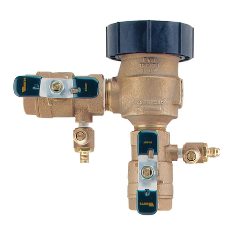
  9. Watts FEBCO 765 Instruction Manual

Watts FEBCO 765 Instruction Manual

Service Instructions
Backflow prevention assemblies must be drained for the winter
in areas where freezing temperatures may occur. If water inside
the assembly should freeze, damage to the assembly and the
system may occur. Proper draining procedures, insulation from
freezing using heat tape, and heated protective enclosures are all
methods of freeze protection.
In order to drain an assembly to prevent freezing, several import-
ant points must be remembered:
1 The assembly can not be adequately drained through the
testcocks. For proper draining follow the instructions detailed
in the drain procedures section.
2. Drain valves must be added on the inlet side and outlet side
of the assembly below the assembly (preferably below the
freeze line if the remainder of the system is to be drained).
3. Compressed air of adequate volume may be used to “blow-
out” the system after the backflow preventer is drained.
4. After removing water from the system and assembly, the
assembly shut-off valves, drain valves and testcocks should
remain in a half open / half closed (45o degree) position to
allow for full drainage of the ball valve shutoffs. If the assem-
bly is installed with ball valve shut-offs, see draining proce-
dure for ball valves on the reverse side of this sheet. The
main shut-off to the system must remain closed during the
winter period.
Draining Procedure
To drain the backflow prevention assembly for protection against
freezing, use the following procedures:
1. Turn off the main shut-off valve (A) which provides water to
the system.
2. Open all inlet and outlet drain valves on the system (B and E).
NOTICE
For any indoor drain valves, ensure that any water draining from
the system is collected to avoid water damage. Open inlet and
outlet shut-off valves on backflow prevention assembly (C and D)
and all testcocks. After fully draining system, leave in half open /
half closed (45o degree) position to allow for full drainage of ball
valve shutoffs. (See the ball valve freeze protection instructions
for more details.)
3. Should you “blowout” the piping system downstream of the
backflow prevention assembly, make sure the outlet drain
valve (E) is open and the backflow prevention outlet shut-off
valve (D) is closed.
4. Connect an air line to the outlet drain valve (E) and introduce
air of adequate volume to clear downstream system of water.
5. NOTICE Open outlet shut-off valves to the backflow
preventer assembly (C and D) to a half open/half closed (45°
degree) position after “blowout” procedure is complete.
6. Leave all drain valves (B and E), testcocks and ball or gate
valves to backflow preventer (C and D) in a hall open / half
closed position for the winter to prevent freezing.
NOTICE
When finished, make sure main shut-off valve (A) remains closed
to prevent accidental refilling of the system. AIso, the main shut-
off valve should be resilient seated to prevent see page of water
into the system.
E
Outlet
Drain Valve
D
A
Main Shut-Off
Valve
B
Inlet Drain
Valve
Valve Pit
C
Instructions for Installing
Model 765
Pressure Vacuum Breaker Draining
Procedure for Freeze Protection
IS-F-765-Winterization
WARNING
!
Read this Manual BEFORE using this equipment.
Failure to read and follow all safety and use information
can result in death, serious personal injury, property
damage, or damage to the equipment.
Keep this Manual for future reference.
Local building or plumbing codes may require modifica-
tions to the information provided. You are required to
consult the local building and plumbing codes prior
to installation. If the information provided here is not
consistent with local building or plumbing codes, the
local codes should be followed. This product must be
installed by a licensed contractor in accordance with
local codes and ordinances.
WARNING
!
Ball Valves
Draining Procedure for Freeze Protection
Ball valves should be drained for the winter in areas where
freezing temperatures may occur. Water will become trapped
between the ball and valve body if the valve is left in either the full
open or full closed position. If water should freeze between the
ball and valve body, damage to the ball valve will occur.
After draining procedures on the backflow prevention assembly
have been completed, all ball valves must be left in a half open /
half closed (45° degree) position as shown in Figure A. Open the
ball valve approximately 45° degrees while draining the pipeline
and assembly to allow water between the ball and valve body to
drain as shown in Figure B. Leave the ball valve in this position
for the winter to prevent freeze damage.
The valve must be closed before the system can be
repressurized.
NOTICE
Open and close ball valves slowly at all times to prevent damage
to the system.
Open 45o
Figure A: Ball Valve in
half open/half closed
45° degree position
Figure B: Cutaway draw-
ing displaying ball valve
in half open/half closed
position
Freeze Protection Ball Valves
Ball Valve Draining Procedure for Freeze Protection
Limited Warranty: FEBCO (the “Company”) warrants each product to be free from defects in material and workmanship under normal usage for a period of one year from the date of original shipment.
In the event of such defects within the warranty period, the Company will, at its option, replace or recondition the product without charge.
THE WARRANTY SET FORTH HEREIN IS GIVEN EXPRESSLY AND IS THE ONLY WARRANTY GIVEN BY THE COMPANY WITH RESPECT TO THE PRODUCT. THE COMPANY MAKES NO OTHER
WARRANTIES, EXPRESS OR IMPLIED. THE COMPANY HEREBY SPECIFICALLY DISCLAIMS ALL OTHER WARRANTIES, EXPRESS OR IMPLIED, INCLUDING BUT NOT LIMITED TO THE IMPLIED
WARRANTIES OF MERCHANTABILITY AND FITNESS FOR A PARTICULAR PURPOSE.
The remedy described in the first paragraph of this warranty shall constitute the sole and exclusive remedy for breach of warranty, and the Company shall not be responsible for any incidental, special
or consequential damages, including without limitation, lost profits or the cost of repairing or replacing other property which is damaged if this product does not work properly, other costs resulting from
labor charges, delays, vandalism, negligence, fouling caused by foreign material, damage from adverse water conditions, chemical, or any other circumstances over which the Company has no control.
This warranty shall be invalidated by any abuse, misuse, misapplication, improper installation or improper maintenance or alteration of the product.
Some States do not allow limitations on how long an implied warranty lasts, and some States do not allow the exclusion or limitation of incidental or consequential damages. Therefore the above
limitations may not apply to you. This Limited Warranty gives you specific legal rights, and you may have other rights that vary from State to State. You should consult applicable state laws to
determine your rights. SO FAR AS IS CONSISTENT WITH APPLICABLE STATE LAW, ANY IMPLIED WARRANTIES THAT MAY NOT BE DISCLAIMED, INCLUDING THE IMPLIED WARRANTIES OF
MERCHANTABILITY AND FITNESS FOR A PARTICULAR PURPOSE, ARE LIMITED IN DURATION TO ONE YEAR FROM THE DATE OF ORIGINAL SHIPMENT.
IS-F-765-Winterization 2043 © 2020 Watts
USA: T: (800) 767-1234 • F: (800) 788-4491 • FEBCOonline.com
Canada: T: (888) 208-8927 • F: (905) 332-7068 • FEBCOonline.ca
Latin America: T: (52) 55-4122-0138 • FEBCOonline.com

Other manuals for FEBCO 765

1

Other Watts Plumbing Product manuals

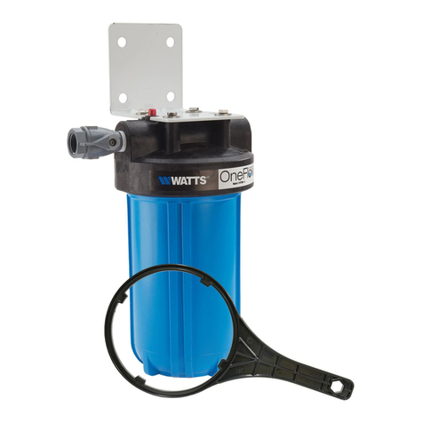
Watts OneFlow OFTWH-C User manual

Watts

Watts OneFlow OFTWH-C User manual

Watts 800M4 Series Operating instructions

Watts

Watts 800M4 Series Operating instructions

Watts SOCLA BA BM User manual

Watts

Watts SOCLA BA BM User manual

Watts Radiant ASTM F1960 Instruction Manual

Watts

Watts Radiant ASTM F1960 Instruction Manual

Watts LFN45B-EZ-M1 Series User manual

Watts

Watts LFN45B-EZ-M1 Series User manual

Watts FEBCO 825YA Series Operating instructions

Watts

Watts FEBCO 825YA Series Operating instructions

Watts 188A Series User manual

Watts

Watts 188A Series User manual

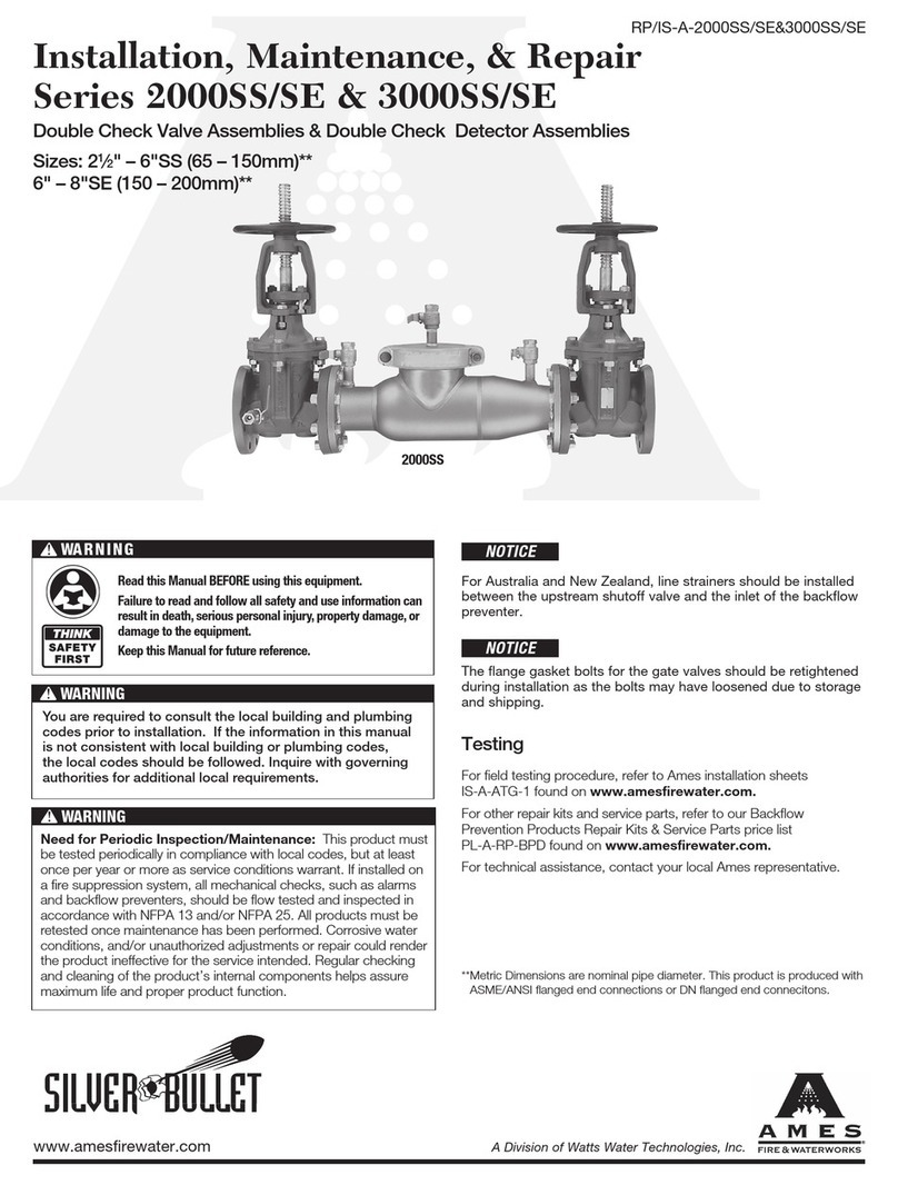
Watts AMES SILVER BULLET 3000SS Series Instruction Manual

Watts

Watts AMES SILVER BULLET 3000SS Series Instruction Manual

Watts AERCO ADMS Series User manual

Watts

Watts AERCO ADMS Series User manual

Watts Hydro-Force LFFRRV-H-C User manual

Watts

Watts Hydro-Force LFFRRV-H-C User manual

Watts 500800 User manual

Watts

Watts 500800 User manual

Watts 15M2 Series User manual

Watts

Watts 15M2 Series User manual

Watts E400 Series User manual

Watts

Watts E400 Series User manual

Watts HKV2013AF Series User manual

Watts

Watts HKV2013AF Series User manual

Watts N45BDU-EZ Series User manual

Watts

Watts N45BDU-EZ Series User manual

Watts FS-200-W Instruction Manual

Watts

Watts FS-200-W Instruction Manual
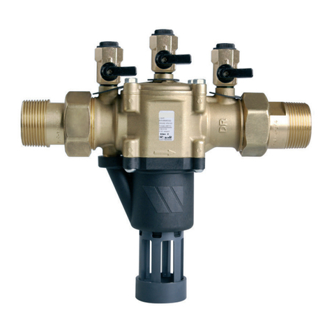
Watts FEBCO 860 Series User manual

Watts

Watts FEBCO 860 Series User manual
Watts 800M4 Series Instruction Manual

Watts

Watts 800M4 Series Instruction Manual

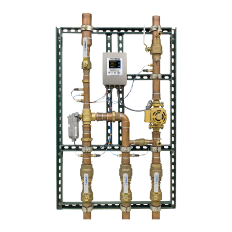
Watts Powers IntelliStation User manual

Watts

Watts Powers IntelliStation User manual

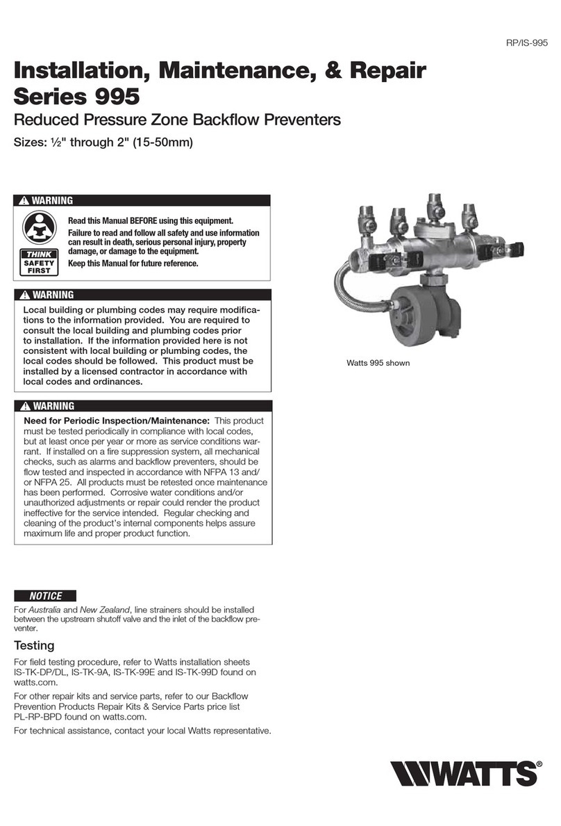
Watts 995 Series Instruction Manual

Watts

Watts 995 Series Instruction Manual
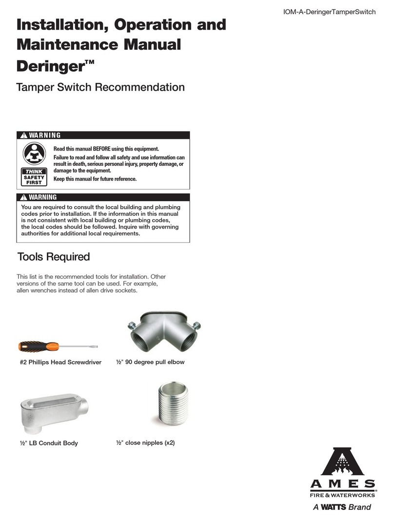
Watts AMES Deringer Series User manual

Watts

Watts AMES Deringer Series User manual

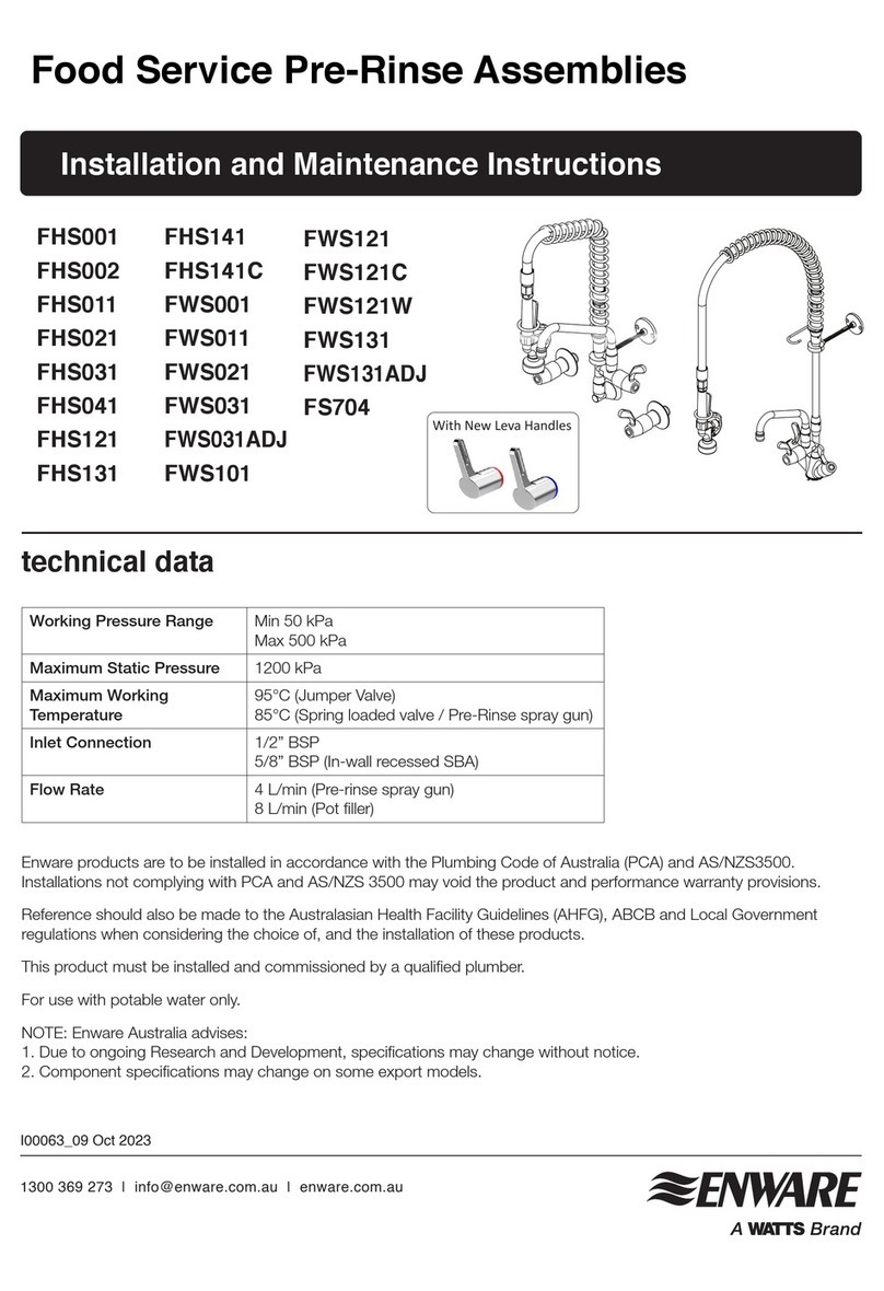
Watts ENWARE FHS001 User manual

Watts

Watts ENWARE FHS001 User manual

Watts Quick-Connect User manual

Watts

Watts Quick-Connect User manual

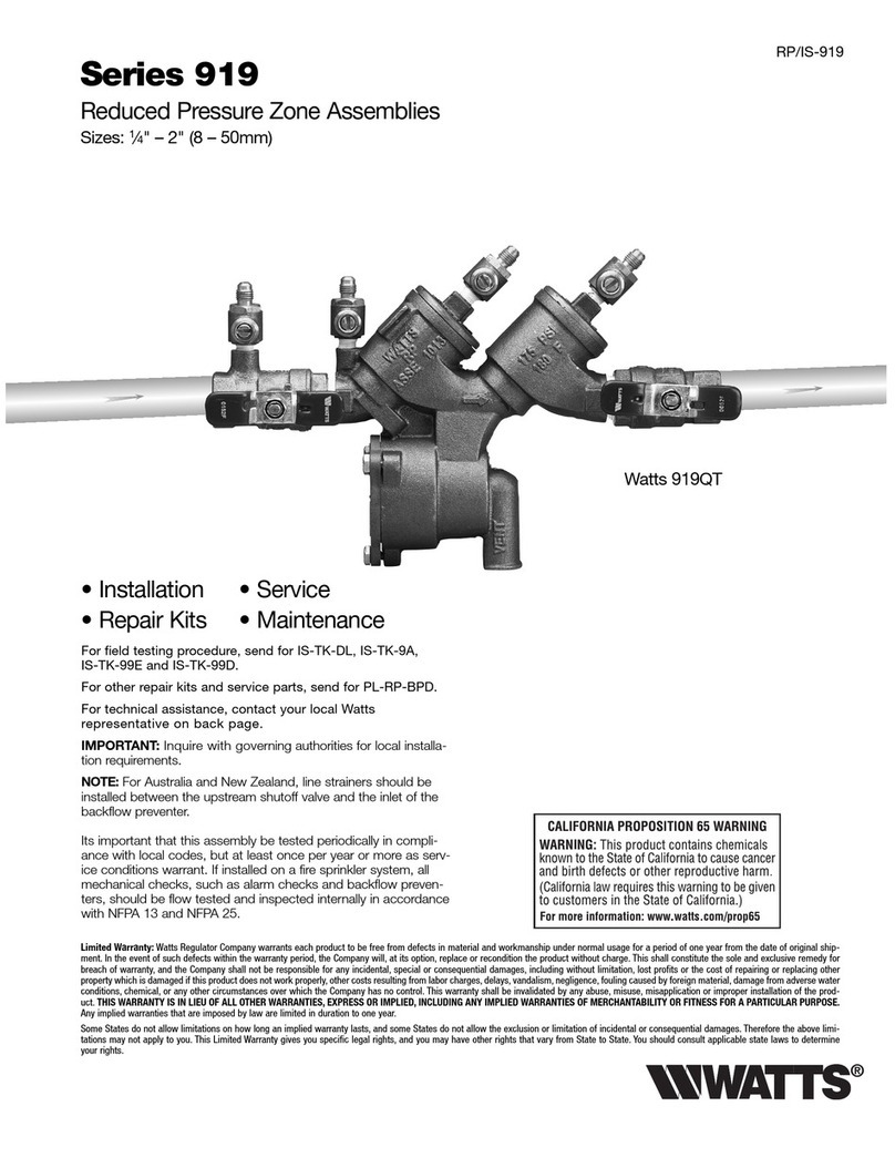
Watts 919 Series User manual

Watts

Watts 919 Series User manual
Popular Plumbing Product manuals by other brands

Mira vigour Installation and user guide

Mira

Mira vigour Installation and user guide

Hans Grohe Talis S 200 72813003 Instructions for use/assembly instructions

Hans Grohe

Hans Grohe Talis S 200 72813003 Instructions for use/assembly instructions

Kalia CITE BF1221 Installation instructions / warranty

Kalia

Kalia CITE BF1221 Installation instructions / warranty

Hans Grohe Allegro E 04076 0 Series Installation instructions / warranty

Hans Grohe

Hans Grohe Allegro E 04076 0 Series Installation instructions / warranty

Axor Chrome 14870001 Installation instructions / warranty

Axor

Axor Chrome 14870001 Installation instructions / warranty

Danze D304036 installation instructions

Danze

Danze D304036 installation instructions

Hans Grohe Bodyvette Stop 28467000 Assembly instructions

Hans Grohe

Hans Grohe Bodyvette Stop 28467000 Assembly instructions

Bradley S19-220DCR Installation

Bradley

Bradley S19-220DCR Installation

American Standard Deck-Mount Kitchen Faucet 6270 Series installation instructions

American Standard

American Standard Deck-Mount Kitchen Faucet 6270 Series installation instructions

Rohl G1655 Installation sheet

Rohl

Rohl G1655 Installation sheet

Kohler K-1844 Installation and care guide

Kohler

Kohler K-1844 Installation and care guide

Hans Grohe Raindance 400 Square Installation/User Instructions/Warranty

Hans Grohe

Hans Grohe Raindance 400 Square Installation/User Instructions/Warranty

Kohler BRAZN K-702242T installation instructions

Kohler

Kohler BRAZN K-702242T installation instructions

Omnires SYSCT11AT Installation and Maintenance

Omnires

Omnires SYSCT11AT Installation and Maintenance

Gessi iSpa 41103 Bath Mixing Program

Gessi

Gessi iSpa 41103 Bath Mixing Program

Sanela SLU 21B Instructions for use

Sanela

Sanela SLU 21B Instructions for use

Allen + Roth 67691W-6204 manual

Allen + Roth

Allen + Roth 67691W-6204 manual

SANIKU DIVISO Assembly instructions

SANIKU

SANIKU DIVISO Assembly instructions

manuals.online logo
manuals.online logoBrands
  • About & Mission
  • Contact us
  • Privacy Policy
  • Terms and Conditions

Copyright 2025 Manuals.Online. All Rights Reserved.