2
System Specications
Maximum Pressure:
All Systems - 100psi (6.8 bar)
Minimum Pressure:
All Systems - 20psi (1.4 bar)
Maximum Temperature: 100°F (38°C)
Minimum Temperature: 40°F (4.4°C)
Feed Water Quality: pH 6.5 to 8.5
Chlorine < 2ppm
Iron (maximum) 0.3 mg/l
Manganese (maximum) 0.05 mg/l
Oil & H2S- None allowed
For all other feed water quality requirements abide by the current
USEPA Safe Drinking Water Act standards.
Inlet/Outlet Connections: 3⁄8" (10mm) NPT for model
QTBRWMAX-1S-1M. QTBRWMAX-2S-1M has 1/2" (15mm)
NPT connections
Maximum Flow Rate:
System Flow Rate and Capacity
System Model Flow Rate Chlorine Capacity
QTBRWMAX-1S-1M 1.5 GPM
(5.7 LPM)
10,000 Gallons
QTBRWMAX-2S-1M 3 GPM
(11.4 LPM)
20,000 Gallons
QT Brew Max line is available in different congurations depending
upon ltration and ow requirements.
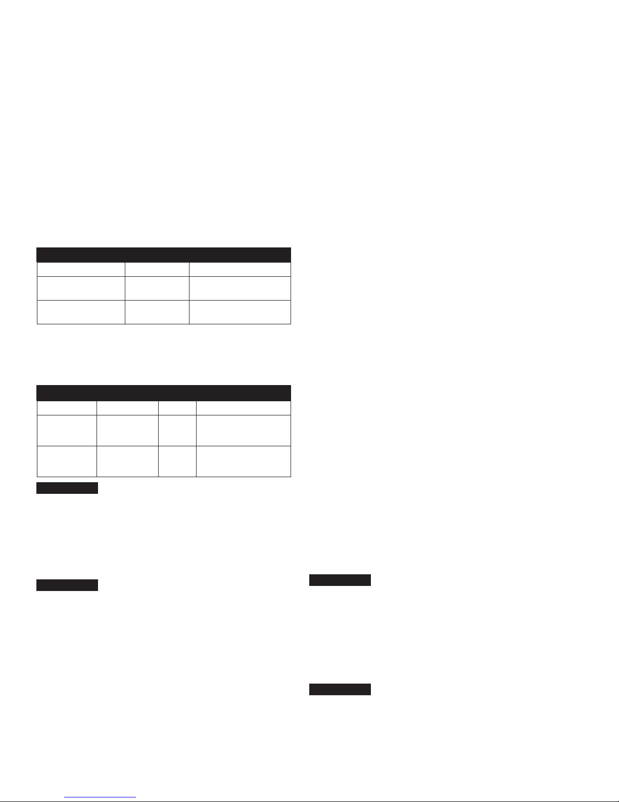
System Replacement Filters
System Model Filter Ordering Code Frequency Description
QTBRWMAX-1S-1M QTBR15S* 6 Months
15" 1 Micron Carbon Block for
Lead Reduction with Phosphate
Scale Control
QTBRWMAX-2S-1M QTBR15 6 Months
15" 1 Micron Carbon Block for
Lead Reduction with Phosphate
Scale Control (2)
NOTICE
Filter cartridges should be changed at end of filter life, due to lack of
filtering performance, or whenever a 15 psi pressure drop or greater
is experienced during normal operation, whichever comes first.
For all replacement filters and components contact your authorized
Hydro-Safe Foodservice representative.
*Note: The QTBR15S is the same filter as the QTBR15. Only the
label position has been changed so that the label faces forward on
single cartridge systems.
NOTICE
Cartridge capacities are estimates and may be less depending
on incoming water quality.
Notice to Installer
• Connect the system to cold water supply only. Water Temperature
cannot exceed 100°F (38°C).
• System must be installed in a vertical, upright and level position.
• Do not use with water that is microbiologically unsafe or of
unknown water quality.
• Notice to user/owner/operator: Please retain this manual for future
reference for parts, maintenance, or troubleshooting.
• It is recommended that all personnel responsible for operation and
maintenance of this product read the precautions, maintenance,
and operation sections of this manual.
Installation Precautions
• Do not install system on line pressure above the rated pressure as
noted in System Specications above.
• Do not install the system on a hot water line. Failure to limit the
water temperature to 100°F (38°C) can result in housing failure and
property damage.
• Do not connect the system backwards with the feed water line
connected to the outlet.
• Do not use liquid pipe thread compounds for threaded
connections. Use Teon®tape only.
• Do not solder plumbing connections that are attached to the
housings or inlet/outlet ttings. System damage may occur due to
high temperature.
• Do not allow the system to freeze. Turn off water supply and drain
the system if temperature falls below 32°F (0°C).
• Do not install system in direct sunlight or where the system will be
exposed to harsh chemicals or may be subjected to being hit by
moving equipment, carts, mops, or any other item that may cause
damage.
• Allow 3" (76mm) minimum clearance under the housings for lter
replacement.
• If water hammer is evident, install water hammer arrestors before
the system.
• Do not over tighten tting connections.
• Always back up valves and ttings with a wrench when installing
ttings to avoid over tightening or loosening existing ttings.
• Do not install the unit behind equipment where it may be difcult to
access the system for future lter replacements.
Position the system in a suitable location. The direction of ow
through the system is left to right. Keep this in mind when
determining installation locations. Do not mount the system near any
source of heat. Also do not mount this system over anything that
may be adversely affected by water.
Operation
With sufcient pressure, operation of this system is completely auto-
matic. Dependable operation involves only monitoring system pres-
sure differential, periodic lter changes, and service documentation.
Installation
There is some light eld assembly required for this system.
Before beginning the installation of this system, please make
sure all components are present. Compare the contents of this
box to the system drawings located at the end of this manual.
As illustrated by the drawings, not all systems utilize pressure
gauges. These drawings will be referenced in the installation
instruction steps.
1. Turn off all equipment to be fed by the system, locate the water
supply shutoff valve and turn it off.
2. Apply Teon tape to the threads of the inlet and outlet valve and
pressure gauges (if supplied for your model). DO NOT USE
PASTE TYPE THREAD SEALANT. Thread the inlet and outlet
valve assemblies into the inlet and outlet ports of the system as
shown on the system drawings in this manual. Install the pres-
sure gauges, if applicable, into the gauge ports as indicated by
the system drawings in this manual.
DO NOT OVER TIGHTEN THESE FITTINGS INTO THE
FILTER HEADS. When installing ttings onto this system, back
any existing receiving ttings with a wrench to prevent tting
movement. Use a wrench to tighten gauges into their
connection ports. Do not twist on gauge case.
NOTICE
Replacement Filters
NOTICE


