wattstopper PW-100-24 User manual

Santa Clara, CA 95050
800.879.8585
Installation Instructions
Specifications
Voltage . . . . . . . . . . .18-24VDC, 24VAC or Half-wave rectified AC
Current Consumption . . . . . . . . . . . . . . . . . . . . . . . . . . . . . .20mA
Power Supply . . . . . . . . . . . . . . . . . . .Watt Stopper Power Packs
Isolated Relay Rating . . . . . . . . . . . . . . . . . . . . .1A @30VDC/VAC
Time Delay Adjustment . . . . . . . . . . . . . . . . . . . .5 to 30 minutes
Walk-Through Mode . .3 minutes if no activity after 30 sec.
Test Mode . . . 5 sec. at initial power up or DIP switch reset
PIR Adjustment . . . . . . . . . . . . . . . . . . .High or Low (DIP switch)
Light Level Adjustment . . . . . . . . . . . . . . . . . . . . . . .8fc to 180+fc
Alerts . . . . . . . . . . . . . . . . . . . . . .Selectable Audible & Visual
US Patents: 5640113, 6617560B2,
A4787722, A4874962
PW-100-24
Passive Infrared Low Voltage
Wall Switch Occupancy Sensor

UNIT DESCRIPTION AND OPERATION
The PW-100-24 Passive Infrared Low Voltage Wall Switch sensors use advanced
passive infrared (PIR) technology.
The PW-100-24 sensor can turn a load on, and hold it on as long as the sensor
detects occupancy. After no movement is detected for the selected time delay,
the lights switch off. A “walk-through” mode can turn lights off after only 3
minutes, if no activity is detected after 30 seconds following an occupancy
detection.
The PW-100-24 has one relay and one ON/OFF button. It also contains a light
level sensor. If adequate daylight is present, the sensor holds the load OFF until
light levels drop, even if the area is occupied. Users can override this function
by pressing the ON/OFF button. See Light Level Adjustment.
Turning The Load ON
The PW-100-24 can be programmed for either Auto ON or Manual ON mode. In
either mode, the load can be turned ON or OFF using the ON/OFF button.
Auto ON
DIP 8 OFF
Load turns ON and OFF automatically based on occupancy. If the
load is turned OFF manually, it stays OFF until 5 minutes after
the last occupancy detection, at which time it reverts to Auto ON
mode. This prevents the load from turning ON automatically
after it was deliberately turned OFF. Pressing the button to turn
lights ON returns the sensor to Auto ON mode.
Manual ON
DIP 8 ON
Occupants must press the ON/OFF button to turn ON the load.
The sensor keeps the load ON until no motion is detected for the
selected time delay. There is a 30 second re-trigger delay. If
occupancy is detected during the delay, the sensor turns the load
back ON. After the re-trigger delay elapses the ON/OFF button
must be pressed to turn ON the load.
Shading indicates default operation and switch setting.
Call 800.879.8585 for Technical Support

Fixed Time Delay
(DIP 1 ON, 2 & 3 OFF)
High (DIP #5 OFF)
Walk-Through
Mode
(DIP #4 ON)
The PW-100-24 turns the load OFF three minutes after
the area is initially occupied, if no motion is detected
after the first 30 seconds. If motion continues beyond
the first 30 seconds, the set time delay applies.
Default setting. Suitable for most applications.
PIR Sensitivity Adjustment
The PW-100-24 constantly monitors the controlled environment and
automatically adjusts the PIR to avoid common ambient conditions that can
cause false detections, while providing maximum coverage.
Time delays are 5, 10, 15, 20 (default), 25, or 30
minutes.
SmartSet™ auto
adjust time delay
and Test Mode
Records typical occupancy patterns. Using this history
(which is constantly updated), it chooses an optimal
time delay from 7 minutes (if the space is usually
vacant) up to 30 minutes (if the space gets heavy
usage). SmartSet behavior starts immediately, and is
refined continually as history is collected.
A Test Mode with a short time delay of 5 seconds is set
when DIP switches 1, 2, & 3 are OFF. It cancels
automatically after five minutes, or when you set a
fixed time delay. To restart Test Mode, change the time
delay setting to any fixed amount and then return it to
the Auto/Test setting.
Reduces sensitivity by approximately 50%. Useful in
cases where the PIR is detecting movement outside of
the desired area (also consider masking the lens) and
where heat sources cause unnecessary activation.
Low, 50%
(DIP #5 ON)
Visit our website for FAQs: www.wattstopper.com
Walk-Through
The Walk-Through mode shortens the time delay to reduce the amount of time
the load is ON after a brief moment of occupancy, such as returning to an office
to pick up a forgotten item then immediately exiting.
No Walk-Through Walk-Through mode disabled.
Time Delays
The PW-100-24 holds the load ON until no motion is detected for the selected
time delay. Select the time delay using DIP switch settings. The sensor
automatically sets the time delay when Auto/Test is enabled for maximum
energy savings.
Call 800.879.8585 for Technical Support
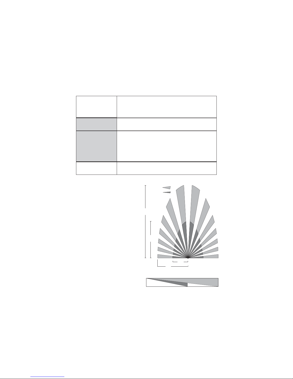
COVERAGE PATTERNS
Coverage testing has been
performed according to the NEMA
WD 7 guideline. For best
performance, use in spaces not
larger than 15’ x 12’.
PIR Sensor
The sensor has a two-tiered, multi-
cell viewing Fresnel lens with 180
degree field of view. The red LED on
the sensor flashes when the PIR
detects motion.
Masking the lens
Opaque adhesive tape is supplied so
that sections of the PIR sensor’s
view can be masked. This allows you
to eliminate coverage in unwanted
areas. Since masking removes
bands of coverage, remember
to take this into account when
troubleshooting coverage
problems.
PIR
Coverage
7.5’
(2.2m)
15’
(4.5m)
20’
(6.1m)
35’
(10.6m)
Major motion
Minor motion
Alerts
The PW-100-24 can provide audible and/or visible alerts as a warning before
the load turns OFF.
"Whistles" twice, at one minute and at 30 seconds
before turning OFF load. “Chirps” 10 seconds before
turning OFF load. “Beeps” three times 10 seconds
before the load goes OFF for Walk-Through.
If Visible Alert is also ON, the one-minute whistle is
replaced by the visible alert.
Audible Alerts
(DIP #7 ON)
No audible warnings provided.
When only one minute is left in the time delay, the load
connected to the relay turns OFF for one second. This
provides a one minute warning before the load(s) are
turned OFF by the sensor.
Visible Alert
(DIP #6 ON)
No Visible Alerts
(DIP #6 OFF)
No visible warnings provided.
No Audible Alerts
(DIP #7 OFF)
4’
(1.2m)
20’
(6.1m)
35’
(10.6m)
0
Top View
Side View
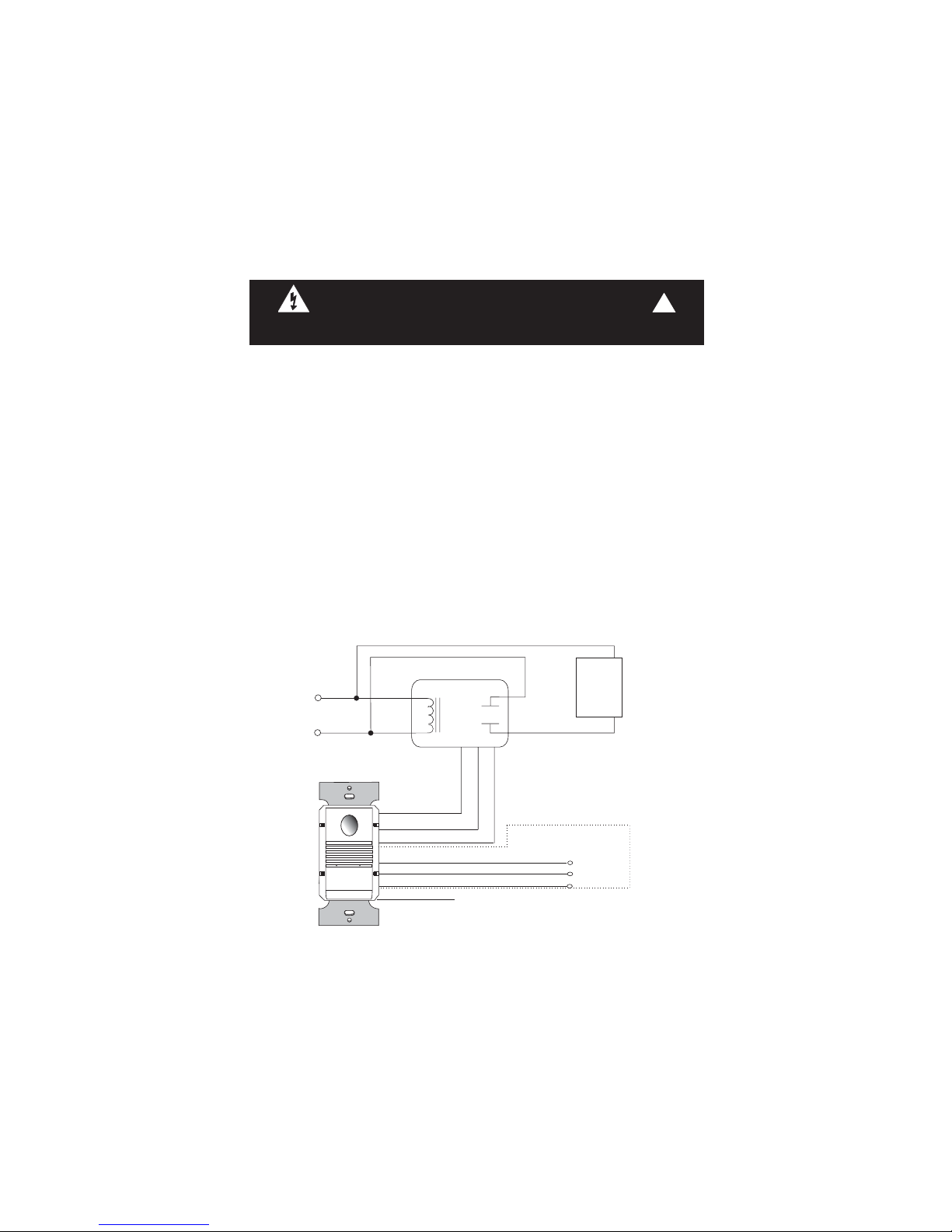
1. Install the power pack according to its instructions.
2. Connect the power pack wires to the sensor as follows:
RED wire (+24VDC) to the +24V IN terminal on the sensor.
BLACK wire (Return) to common (COMM.) terminal on the sensor.
BLUE wire to control output (CTRL. OUT) terminal on the sensor.
3. Wire the Isolated Relay. The Isolated Relay is rated for 1A @ 30VAC/VDC.
Connect the wires necessary to the application that requires this output:
Normally Closed (N.C.) - Open when occupancy is detected.
Relay Common (must be used for proper operation)
Normally Open (N.O.) - Closed when occupancy is detected.
The bottom terminal on the sensor is not used.
4. Turn the power on.
5. Test and adjust the sensor if necessary.
6. Attach the cover plate.
INSTALLATION
WARNING
TURN THE POWER OFF AT THE CIRCUIT BREAKER
BEFORE INSTALLING POWER PACKS OR SENSORS.
!
Visit our website for FAQs: www.wattstopper.com
PW-100-24 Wiring
Common
White (Neutral)
Red
(Load)
Red (Line)
White
Black
Hot
Neutral Power
Pack
Blue
Black
Red
Lighting
Load
Control Outputs
+24 VDC
Isolated Relay Outputs
Normally closed contact
Common
Normally open contact
Not used
DELAY
PIR 50%
WALK
AUD. ALERT
RLY 1 MAN
RLY 2 MAN
VIS. ALERT
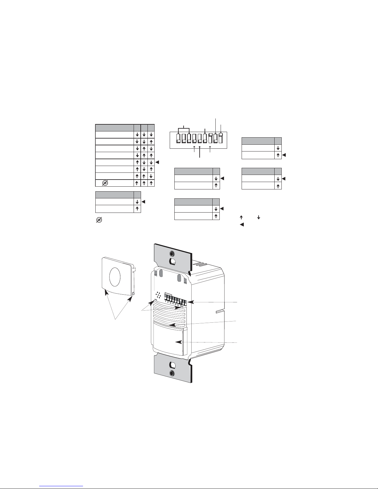
ON/OFF Button
DIP Switches
Detection LED
PIR Lens
DIP SWITCH SETTINGS
=ON =OFF
=Factory Setting
8
Auto On
Manual On
ON Mode
5
High
Low, 50%
PIR Sensitivity
7
Disabled
Enabled
Audible Alert
4
Disabled
Enabled
Walk-Through
912345678
Time
Delay
Walk-Through
ON
ON Mode
Not Used
Audible Alerts
PIR Sensitivity
Visible
Alerts
Auto/Test
10 minutes
15 minutes
20 minutes
25 minutes
30 minutes
override
5 minutes
123
Time Delay
Bypass occupancy & light level
functions. Load is manually
controlled with ON/OFF button.
6
Disabled
Enabled
Visible Alert Switch 9 is not used
Call 800.879.8585 for Technical Support
Button
Hinges
Tabs

TROUBLESHOOTING
Lights do not turn ON with motion (LED does flash)
1. Press and release the ON/OFF button to make sure that the correct
lights come ON. If the lights do NOT turn ON, check wire connections. If
the lights turn ON, verify that the correct On Mode is selected in DIP
switch 8.
2. Check to see if light level control is enabled: cover the sensor lens with
your hand. If the lights come ON, adjust the light level setting.
3. If lights still do not turn ON, call 800.879.8585 for technical support.
Lights do not turn ON with motion (LED does not flash)
1. Press and release the ON/OFF button to make sure that the correct
lights come ON. If the lights turn ON, verify that Sensitivity is on High.
2. Check the wire connections. Verify that connections are tightly secured.
3. If lights still do not turn ON, call 800.879.8585 for technical support.
ADJUSTMENTS
Sensor Adjustment
Remove the wall plate. Remove the button cap by firmly squeezing together the
top sides of the button assembly. Gently pull it away from the unit.
When the adjustments are completed, replace the button cap by inserting its
hinges into the tabs on the main unit and then squeeze the top of the button while
pressing it into the unit. Reinstall the cover plate.
Light Level Adjustment
The light level can be set with loads ON or OFF. To enable light level control and
set the threshold: 1) Make sure the room is lit appropriately. 2) Put the sensor into
TEST mode. You have 5 minutes to complete the procedure. 3) Press and hold the
ON/OFF button for 3 seconds, until you hear a beep. 4) Step away from the sensor.
After 25 seconds a beep sounds, indicating that the threshold level is set. This
threshold is retained, even if power is lost, until it is re-set or disabled.
To disable light level control, press and hold the ON/OFF button for 7 seconds,
until a double beep tone sounds.
Reset to Default
To reset the PW to factory settings, press and hold the ON/OFF button for 10
seconds, until a triple beep sounds. This resets the sensor occupancy history and
disables light level control (the brightest ambient light will not hold the light OFF).

ORDERING INFORMATION
Warranty Information
Watt Stopper/Legrand warranties its products to be free of defects in materials
and workmanship for a period of five years. There are no obligations or
liabilities on the part of Watt Stopper/Legrand for consequential damages
arising out of or in connection with the use or performance of this product or
other indirect damages with respect to loss of property, revenue, or profit, or
cost of removal, installation or reinstallation.
Units come in White (-W), Light Almond (-LA), Ivory (-I), Gray (-G), Black (-B).
Add color designator to catalog number when ordering.
* One ASP-211 Cover Plate for single gang box is included with each switch.
2800 De La Cruz Boulevard, Santa Clara CA 95050
Technical Support: 800.879.8585 • www.wattstopper.com
07178r1 12/2006
Catalog # Description
PW-100-24 Passive infrared low voltage wall switch sensor;
18-24VDC, 24VAC or Half-wave rectified AC
BZ-100 Power pack; 120/277VAC, 50/60Hz, 150mA
20A ballast or incandescent, 1hp @120/240VAC
ASP-422 Blank cover plate for 2-gang box
ASP-432 Switch option cover plate for 2-gang box
Lights do not turn OFF
1. There can be up to a 30 minute time delay after the last motion is
detected. To verify proper operation, set DIP switch 1 to ON, then reset
switches 1, 2, and 3 to OFF to start Test Mode. Move out of view of the
sensor. The lights should turn OFF in approximately 5 seconds.
2. Verify that the sensor is mounted at least six feet (2 meters) away from
any heating/ventilating/air conditioning device that may cause false
detection. Verify that there is no significant heat source (e.g., high wattage
light bulb) mounted near the sensor.
3. If the lights still do not turn OFF, call 800.879.8585 for technical support.
Sensing motion outside desired areas
1. Select PIR Sensitivity – Low (DIP switch 5 = ON) if necessary.
2. Mask the PIR sensor’s lens to eliminate unwanted coverage area.
Table of contents
Other wattstopper Switch manuals

wattstopper
wattstopper WI-200 User manual

wattstopper
wattstopper PW-203 User manual

wattstopper
wattstopper EMTS-100 User manual

wattstopper
wattstopper LVSW Series User manual

wattstopper
wattstopper PW-100-24 User manual

wattstopper
wattstopper LMSW-105 User manual

wattstopper
wattstopper DW-103 User manual

wattstopper
wattstopper LMSW-102 User manual

wattstopper
wattstopper LVSW-101 User manual

wattstopper
wattstopper WI-200 User manual


