Auditor 6W
Complete these ve easy steps,
then start monitoring your site.
1. Before you begin
2. Connect your Auditor
3. Congure your WiFi settings
4. Use the onboarding tool
5. Validate that your installation is correct
1. Before you begin
Ensure you have the equipment - See Auditor 6W checklist below. You’ll need
an internet-connected smart device (e.g. smartphone, tablet, laptop) to congure
the Auditor and capture information about the installation. A marker is useful for
numbering Current Transformers and cables during installation. You’ll need a clamp
meter for checking current measurements.
Check - That you have 35mm wide space available on the DIN rail. If there is
not space, additional DIN rails may be mounted in the cabinet or an external
enclosure used. Ensure that Current Transformer can accommodate the cable size
(i.e. cable diameter ts within CT opening width).
Ensure there is a way to isolate the Auditor voltage inputs - An existing or new
circuit breaker can be used depending on the regulations in your jurisdiction. A
breaker is not included in the Auditor package.
WiFi network details & signal - Ensure that you have the WiFi network name
and password on hand. With your smartphone or tablet ensure that there is a
WiFi signal at the installation site. If there is no reception you’ll need a WiFi range
extender. Once the Auditor is installed you’ll be able to check for adequate
signal strength.
Auditor 6W hardware checklist:
• Monitoring device - 2-unit wide DIN-mount
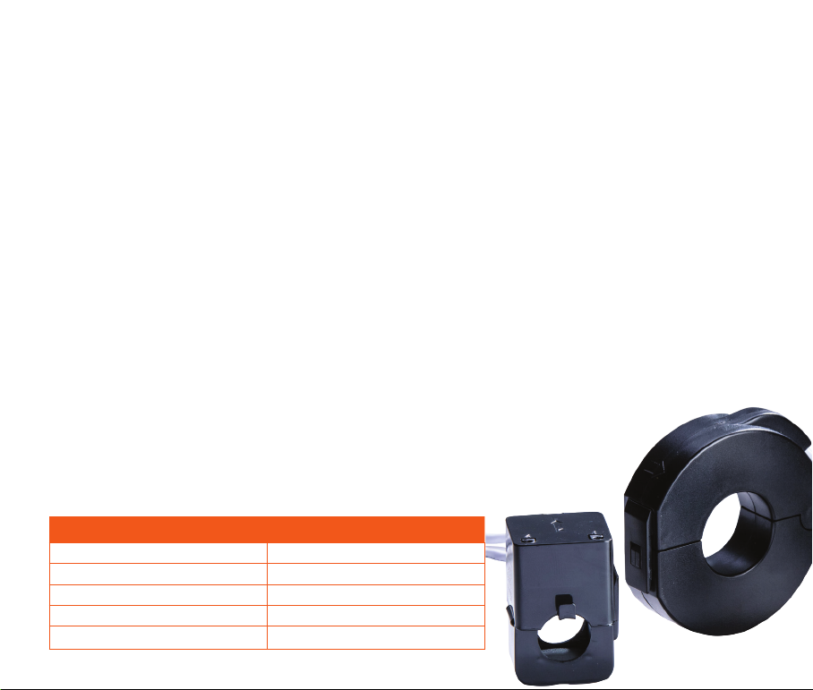
• CTs - supplied in sets of 3 (one or two sets)
• Wiring tails - single-phase, 3-phase or both
• Connectors - green-coloured plastic plugs.
ATTENTION: Must be installed by a licensed electrician in accordance with standard electrical
safety regulations in your jurisdiction.