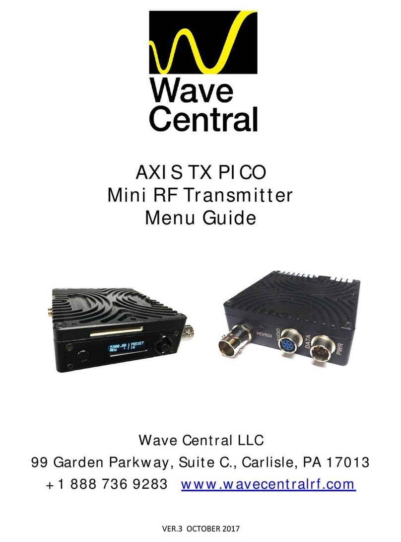
Wave Central Axis Series Operating instructions

1
Axis Series – TX User and Programming
Guide
ATXT1 AXTX1M – Mini AXTX1MB – Mini-B
Wave Central LLC
99 Garden Parkway, Suite C., Carli le, PA 17013
+1 888 736 9283 www.wave-central.com

2
Content
Contents__________________________________________________________
2
Sy tem De cription 4
What are the Axis Series Transmitters? 5
App ications 7
Variants and Options 8
Main Connectors 9
App icab e Unit Software 14
Placard and Marking 15
Genera 15
Exterior P acards and Marking System (AXTX1) 15
Interior P acards and Marking System 16
Exterior Co or Schemes and Marking System 16
Caution and Warning 17
Cautions and Warnings 17
Specific Absorption Rates (SAR) FCC Exemption 18
Hea th and Safety 18
Panel , Di play , Alarm, Indicator and Control 19
Genera 19
Pane System – AXTX1xx 19
A arm System – AXTX1xx 19
Indicator System – AXTX1xx 19
Contro Pane System – AXTX1xx 20
Connectivity 21
Genera 21
Power - AXTX1 21
Signa - AXTX1 21
Contro - AXTX1 21
Setting up your Tran mitter 23
Genera 23
Connecting Antennas 23
Down Converter System 23
Up Converter System 23
Connecting Signa s – AXTX1 23
Connecting Power – AXTX1 24
A Look at the Disp ay – AXTA1 25
A Look at the TX Contro System – AXTX1 25
A Look at the Menu Structure – AXTX1 27
Ba ic Operation 29

3
Genera 29
Starting and Stopping – AXTX1 29
Working with the Contro Pane – AXTX1 29
Advanced Operation 34
Genera 34
Encryption 34
Control Sy tem 37
Genera 37
Connecting your PC to your Radio 37
Configuring Basic Settings 39
Configuring the Radio 47
Understanding the Unit Information Tab 47
Configuring the Modu ation Parameters 48
Configuring the Audio Parameters 52
Configuring the Video Parameters 53
Configuration Unit Parameters 56
Care and Maintenance 60
Genera 60
Dai y Care and Charging 60
C eaning 60
Storage 60
Repairs 60
Appendix A-Glo ary 61
Genera 61
G ossary 61

4
1. Sy tem De cription
The subject equipment of this User Guide is identified as fo ows:
Equipment Title
Part Number
Fu Size Camera Back Transmitter
AXTX1
Miniature Transmitter
AXTX1
M
Miniature B Transmitter
AXTX1
MB
Figure 1-1 – AXTX1: Camera Back Tran mitter
Figure 1-2a – AXTX1M - Mini Tran mitter

5
Figure 1-3b – AXTX1MB: Mini-B Tran mitter
1.1 What are the Axi Serie Tran mitter ?
The new Axis series transmitter comes in three different packages designed to suit the needs of many
different types of app ications. These transmitters both offer exce ent coverage, ow de ay performance
and mu tip e format/frame rate capabi ities that enab e users to acquire stunning images via a wire ess
connection, at extended non ine of sight ranges. By using 2
nd
generation MPEG4 H.264 compression
techno ogy, users can now dep oy 2 or 3 cameras within the same bandwidth previous y required by a
sing e MPEG2 system. A modes of DVB-T modu ation are a so supported.
The increased compression and efficiency of the MPEG4 H.264 encoder offers users additiona range with
the added benefit of sma size, ow atency and ow power consumption. In particu ar, high qua ity HD
transmissions are now possib e using 40% ower band width requirements than those of conventiona
MPEG2 systems need, a owing for HD transmission in a sing e 8MHz DVB-T channe and a so being ab e to
use very robust error correction and modu ation settings. Bui t with a so id a uminum housing, the abi ity
to transmit images in a non- ine of sight environment at ranges we over a ½ mi e and its ow de ay
capabi ities makes this transmitter a very formidab e workhorse to suit a most a your RF needs.
The AXTX1 camera back transmitter is a rugged, digita video transmitter, idea for Sports, ENG News and
other Broadcast app ications and the AXTX1M-Mini and AXTX1MB-Mini B are sma er packaged version
geared towards Digita Cinema and Video Assist app ications.
The AXTX1 camera back transmitter can have either Anton Bauer or Sony “V” Mount battery p ates
insta ed to faci itate easy mounting to most camera types. The AXTX1M-Mini has a Sony “mini” battery
mount, as we as a threaded mounting ho e on the bottom of the unit to attach to a wide range of camera
brackets for easy mounting of the AXTX1-Mini to many different sty e cameras. Whi e the Axis series
transmitters can be operated with a most any receiver that supports DVB-T signa s, we recommend using it
with the Wave Centra AXRX1 receiver. The AXRX1 receiver is avai ab e in many different configurations
with options for 2-way, 4-way, 6-way and 8-way diversity.

6
1.2 Feature and Benefit
It can be very usefu to understand how the features of the unit yie d tangib e benefits to you. This tab e
summarizes these features and, more important y, the benefits.
Features and Benefits Tab e
Feature
Benefit to you
Digita COFDM Modu ation.
Exce ent performance
-
Resistant to mu tipath
interference, de ivers high qua ity video and
audio, even in non- ine of sight operation.
Low De ay H.264 SD & HD encoding.
Robust
transmission and minima atency,
switches easi y with wired cameras.
Comp iant DVB
-
T
6/7/8MHz
.
True mu ti
-
mode operation
-
Simp e
integration with your current equipment.
ASI input and output.
A ows for different types of app ications: RF
Transmitter or Portab e H.264 Encoder.
High Efficiency 100mW RF Amp
(Coo Operation)
Exce ent range in non
-
ine of sight
environments ike stadiums and arenas.
Compact and Power Efficient
Transmitters
Low power consumption, 10W
Two mode s a ow for the type of tran
smitter
just where you need it. Sized right to ensure
the success of your operation.
HD
-
SDI/SDI with embedded audio input
HDMI input with embedded audio input
video input
Easy connections connect to your current
cameras. Added f exibi ity of using HD
consumer eve HDMI cameras.
Choice of different icensed and un
-
icensed frequency bands.
(1.4, 2, 5.8, 6.4, 6.8, 7GHz Avai ab e)
Choose the frequency that best suits your
operations. Se ect icense free bands for some
operations. Avoid c uttered parts of the
icensed radio spectrum.
Sixteen Presets Avai ab e
You can estab ish 16 different parameters to
inc ude: Preset frequencies, COFDM
conste ations, video and audio settings, into
any of sixteen presets. Configure the
transmitter once and then users can se ect
from the front pane .
Disp ay Screen and PC GUI
Software Driven
-
Simp e and fast to dep oy
and operate – Saves you time and minimizes
operator error.
AXTX1
M1 Camera Back Transmit
ter
Suitab e for Sports, ENG News and other
Broadcast app ications

7
AXTX1
M Mini about the size of an iPhone
Digita Cinema and Video Assist app ications
AXTX1
MB Mini
-
B
Digita Cinema and Video Assist app ications
1.3 Application
The Broadcast Transmitter has been designed to operate in mu tip e ro es in many environments. Here are
some examp es:
1.1 Professiona Camera Back App ications – Sports and News
We can supp y either Anton Bauer or Sony “V” mounting p ates that enab e the camera back transmitter to
be direct y connected to professiona cameras.
The Sony “V” mount, for examp e enab es the transmitter to be mounted direct y onto cameras such as the
SONY PDW Series Cameras and Thomson 8000 Series. The transmitter mounts between the camera and
the battery. The camera is powered from the battery, through the AXTX1 transmitter, powering both units.
The AXTX1 is a so avai ab e with Anton Bauer connectors to direct y mount onto Panasonic and Ikegami
ENG type cameras.
1.2 He icopter Integration for Sports, News and Traffic Coverage
A variety of insta ation options can be made much simp er and easier to operate, by using either of the
AXTX1 transmitters. By having ASI in/out connectors, the AXTX1 a ows for specific “He i-Te e”
configurations and options.
1. ASI out: Can be used to encode an HDSDI signa from a gimba mounted camera to ASI, which is then
fed to an RF amp ifier and direct y coup ed to an antenna. (Minima RF oss)
2. ASI in: Can be used in an aeria “re-trans” system. Signa s sent up to a he icopter from ground vehic es
and then sent to remote receive sites, mi es away.
3. The sma ightweight AXTX1-Mini is perfect y suited for these types of app ications.
1.2.1 System Integration into Vehic es or Aircraft
Users shou d be aware of the fo owing issues when integrating the equipment into vehic es.
1. For the additiona range required in vehic e app ications, the use of amp ifiers shou d be considered.
Interconnection between the transmitter and any power amp ifier shou d be kept as short as possib e,
but where this is not possib e, specia attention shou d be taken to use on y ow oss cab es.
2. Long cab e runs from the RF output to the antenna shou d be avoided, for maximum RF output.
3. The antenna shou d be mounted vertica y idea y, and exposed to free space.
4. The equipment shou d be supp ied with a c ean supp y in the range 7V to 18V and capab e of 1.10A
maximum at 12VDC. Care shou d be taken to avoid direct supp y from the vehic e 12V which can be
very noisy. Power conversion wi be required for 24V vehic es.
5. The video input can be connected across ong video cab e engths so remote y mounted cameras shou d
pose no prob em.
6. Insure for proper venti ation of equipment, especia y RF transmitter and Amp ifiers.

8
1.3 Variant and Option
1.3.1 Variants – AXTX1 Camera Back Transmitter, with Camera Paint
There are severa major variants of the AXTX1 Camera Back Transmitter:
Operating Frequency Band
Model/Part Number
AXTX1
CBT
1.990
-
2.492
GHz 100mW
AXTX1
-
2G
AXTX1
CBT 5.
730
-
5.
840
GHz 100mW
AXTX1
-
5G
AXTX1
CBT 6.4
36
-
7.120
GHz 100mW
AXTX1
-
7G
1.3.2 Variants – AXTX1M – Mini TX
There are a so three variants of the AXTX1M – Mini TX Transmitter:
Equipment Title
Part Number
AXTX1
Mini
TX
1.990
-
2.492
GHz 100mW
AXTX1
M
-
2G
AXTX1
Mini
TX
5.
730
-
5.
840
GHz 100mW
AXTX1
M
-
5G
AXTX1
Mini
TX
6.4
36
-
7.120
GHz 100mW
AXTX1
M
-
7G
1.3.3 Variants – AXTX1MB – Mini-B TX
Equipment Title
Part Number
AXTX1
Mini
-
B
TX
1.990
-
2.492
GHz 100mW
AXTX1
MB
-
2G
AXTX1
Mini
-
B
TX
5.
730
-
5.
840
GHz 100mW
AXTX1
MB
-
5G
AXTX1
Mini
-
B
TX
6.4
36
-
7.120
GHz 100mW
AXTX1
MB
-
7G
1.3.4 Accessory Options
Equipment Title
Part Number
V
-
Mount Battery P ates (
AXTX1
on y)
TX
-
VBAT
AB Battery P ates (
AXTX1
on y)
TX
-
ABBAT
1.3.5 Licensing Options
Encryption: AES 128 is avai ab e upon request

9
1.4 Main Connector
Here are the unit’s main connectors:
1.4.1 AXTX1 Broadcast Transmitter – Front View
Figure 1-4 AXTX1 Front View Connector
S
erial
Item
1
SMA Connector for 450MHz Camera Contro Antenna.
2
N Connector for
AXTX1
Main RF Antenna.
3
Ta y Connector.
1
2
4
7
3
5
6

10
4
XLR Connectors (x2) Ana og Audio In.
5
L
EMO
4 pin fema e connector
for CCU, camera paint system (RS
-
232)
6
Hirose 6 pin fema e connector
for
CCU, camera paint system
(RS
-
422)
7
BNC Connector for HD/SDI Video
Input.
1.4.2 AXTX1 Broadcast Transmitter - Bottom View
Figure 1-5 AXTX1 Bottom Connector
Serial
Item
1
Unit’s Interna Fan On/Off Button. (For imited fan off operation)
2
USB Programming
Connector to Program TX Unit.
3
LEMO 4Pin Connector for Externa DC Power for Main Unit.
4
BNC ASI Video Input.
5
BNC ASI Video Output.
1
2
3
4
5

11
1.4.3 AXTX1 Broadcast Transmitter - Top View
Figure 1-4 AXTX1 Top Connector
Serial
Item
1
DC Power NOT USED
2
Type N Connector fema e, RF Output
3
RF output Indicator
4
SMA fema e connector for Paint System Antenna
1
2
3
4

12
1.4.4 AXTX1 Broadcast Transmitter – Left Side View
Figure 1-5 AXTX1 Left Side View
Serial
Item
1
Transmitter Contro Pane and Disp ay
2
Camera Mount P ate
3
Camera/Transmitter Battery Mount P ate
4
Transmitter/Paint Main DC Power Switch
1
3
4
2

13
1.4.5 AXTX1 Broadcast Transmitter – Right Side View
Figure 1-6 AXTX1 Right Side View
Serial
Item
1
Camera Contro Unit (CCU) Pane and Disp ay for Paint
2
Indicator, Paint Data connection with base station
3
HDMI
Type A
input with embedded audio input
and video input
1
2
3

14
1.5
Applicable Unit Software
Each Transmitter has two software e ements:
Firmware that runs the device, via board eve FPGA’s. (Fie d Programmab e Gate Array)
And Control Application that is run from a Windows based PC, externa of the transmitter.
1.5.1 Interna Software
A though much of the transmitter is bui t up of hardware components, many of the sophisticated features
are imp emented via firmware programmed into the FPGA’s.
When you perform a firmware upgrade, a comp ete firmware insta ation package is provided which
contains a the required upgrade codes.
1.5.2 Contro App ication
For customized operation and unit configurations, connecting to a PC and running the transmitter Control
Application wi give the user much more g oba command contro of the unit’s settings and parameters.
Here i a creen hot of what the Tran mitter Control Application look like:
Figure 1-6 Tran mitter Control Application

15
2. Placard and Marking
Which mode do I have? What is its Seria Number?
The information covering p acards, abe s, markings, etc., showing the part number, egend and ocation of
each p acard, abe , or marking required for safety or maintenance significant information.
2.1
General
You’ need to be ab e to quick y identify equipment types and seria numbers you have and at what
frequencies your systems are designed to work. You may need to find the Seria Number during a support
ca for examp e.
The simp est way is to check the p acards and markings on the units and this section shows you how to
decode them. The AXTX1 is shown as an examp e.
2.2
Exterior Placard and Marking Sy tem (AXTX1)
The system information that inc udes p acards, abe s, and markings required for servicing instructions,
inspections, cautions, warnings, etc.
The outside of each Broadcast Transmitter unit is marked with severa p acards:
Seria Number P acard
Product P acard
Warranty Void P acard
2.2.1 Seria Number P acard
Figure 2-1 Serial Number Placard AXTX1

16
2.2.2 Product Operating Range and Warranty Void P acard
Figure 2-2 AXTX1 Product and Warranty Void Placard
Serial
Item
1
Product code and frequency range, 5.5GHz to 6.0GHz in this examp e.
2
Warranty
Void, if sea is damaged.
2.3
Interior Placard and Marking Sy tem
The system information covering p acards, abe s, and markings required for genera interior and
emergency information, instructions, cautions, warnings, etc.
There are no interior p acards and markings that wi concern the operator of this unit.
2.4
Exterior Color Scheme and Marking Sy tem
This system information inc udes specifications and requirements covering exterior co or and re ated
markings.
2.4.1 Enc osure Co or
The main enc osure is anodized in b ack.
2.4.2 Pane Markings
The markings on the Axis Series are in white.
1
2

17
3. Caution and Warning
3.1
Caution and Warning
Serial
Area
Note
1
Enc osures
Do not remove any factory insta ed screws or fastenings.
Damage to the units may resu t and void any warranties.
On y authorised, trained personne shou d open the product.
There are no functions that required the user to gain access to
the interior of the product. There are no user serviceab e parts
inside.
2
Maintenance
Other than c eaning, no schedu ed maintenance is required to
ensure proper function of the unit.
3
Environment
The equipment shou d not be used in hazardous or corrosive
atmospheres. Users are reminded of the necessity of comp ying
with restrictions regarding the use of radio devices in fue
depots, chemica p ants and ocations where exp osives are
stored and/or used.
4
Power Supp y
Ensure that the power supp y arrangements are adequ
ate to
meet the stated requirements of each product. Observe a
e ectrica safety precautions.
5
E ectro Static
Discharge
(ESD)
Precautions
ESD guide ines must be fo owed for this e ectrostatic sensitive
device.
6
Lightning
Strike
There is a risk of
ightning strike to antennas. The equipment
shou d not be assemb ed in an area at the time of ightning
activity. Antennas shou d be adequate y protected from
ightning strikes.
7
Working at
Height
Observe caution when ocating the device at height, for
examp e on a mast. Ensure the unit is we secured to prevent it
fa ing and injuring personne .
8
Risk of Eye
Injury
Care shou d be taken to avoid eye contact with the antennas.
9
Cab es
Connecting cab es shou d not be positioned where they are
ike y to become damaged or were they may present a trip
hazard.
10
Therma
Contro System
Any powered device wi a ways produce heat as a by
-
product of
its operation. If you operate this device in an enc osed space
you must ensure it has adequate airf ow to keep it coo .
A so, if worn c ose to the body, care must be taken to protect
the operator from excessive temperatures.

18
Serial
Area
Note
11
RF Emission
System
When using this device p ease ensure a distance of 20cm is
maintained between your device and your body whi e the
device is transmitting.
12
Aircraft Safety
Use of this equipment on board aircraft is strict y forbidden. Use
of radio transmitter equipment in an aircraft can endanger
navigation and other systems.
3.2
Specific Ab orption Rate (SAR) FCC Exemption
This device is exc uded from SAR testing since the separation distance is more than 20cm per KDB 447498

19
4. Panel , Di play , Control , Indicator and
Alarm
4.1
General
You’ need to be ab e to find a the interface connections and contro s on the unit. You’ a so need to be
ab e to identify and interpret any a arms or indicators. This section wi he p you identify a these features.
Each Axis-Series Broadcast Transmitter has severa pane s which contain a the interface connections for
the units and the contro s and indicators. There is an operationa contro pane on one pane of the unit.
The next section describes the transmitter contro pane for the a Axis Series Broadcast Transmitters.
4.2
Panel Sy tem – AXTX1
The AXTX1 has two significant disp ay pane s:
Transmitter Contro Pane
CCU, Camera Contro Unit, Paint for AXTX1 on y.
4.3
Alarm Sy tem – AXTX1 Serie
The right LED indicator is an a arm indicator.
4.4
Indicator Sy tem – AXTX1 Serie
User information is disp ayed on the disp ay screen or on the Contro app ication. Two LED’s are ocated
above the TX indicator pane screen. The GREEN LED indicates, contro pane is communicating with the
main board. The right LED indicator i uminates RED for an
a arm
, as indicated be ow.
Figure 2-3 AXTX1-Serie TX Control Panel
TX

20
4.5
Control Panel Sy tem – AXTX1 Serie Tran mitter
Cancel/Back Joy tick/Confirm
Figure 2-3a AXTX1-Serie TX Control Panel
The contro pane ocated on the right pane has two push buttons. Here’s what they do:
4.5.1 Joystick/Confirm Button (2)
Button
Doe thi …
Joystick/Confirm
Button
Move the joystick for UP,
DOWN, LEFT and RIGHT.
Press the joystick for ENTER.
4.5.2 Cance /Back Button (3)
Button
Doe thi …
Cance /Back
Button
Press to cance action or go back one eve .
TX
Other manuals for Axis Series
1
This manual suits for next models
12
Table of contents
Other Wave Central Transmitter manuals
