Vislink HDX-1100 User manual
HDX-1100
Aircraft/Terrestrial High
Power SD/HD Video
Transmitter
User and Technical Manual
Manual Part No. 400609-1 Rev. A - Sept 2011

Copyright © 2010
Part number 400609-1
Printed in U.S.A.
Authorized EU representative: Vislink PLC
Quality Certification Vislink is certified to ISO 9001:2008.
The Vislink trademark and other trademarks are registered trademarks in the United States and/or other countries.
Microsoft®,Windows®, and Internet Explorer® are registered trademarks of Microsoft Corporation in the United States
and/or other countries.
Proprietary Material The information and design contained within this manual was originated by and is the property
of Vislink. Vislink reserves all patent proprietary design, manufacturing, reproduction use, and sales rights thereto, and
to any articles disclosed therein, except to the extent rights are expressly granted to others. The foregoing does not
apply to vendor proprietary parts. Vislink has made every effort to ensure the accuracy of the material contained in this
manual at the time of printing. As specifications, equipment, and this manual are subject to change without notice,
Vislink assumes no responsibility or liability whatsoever for any errors or inaccuracies that may appear in this manual
or for any decisions based on its use. This manual is supplied for information purposes only and should not be
construed as a commitment by Vislink. The information in this manual remains the property of Vislink and may not be
used, disclosed, or reproduced in any form whatsoever, without the prior written consent of Vislink. Vislink reserves the
right to make changes to equipment and specifications of the product described in this manual at any time without
notice and without obligation to notify any person of such changes.
General Safety Information The following safety requirements, as well as local site requirements and regulations,
must be observed by personnel operating and maintaining the equipment covered by this manual to ensure awareness
of potential hazards. This equipment has been tested and found to comply with the limits for a Class A digital device,
pursuant to Part 15 of the FCC Rules. These limits are designed to provide reasonable protection against harmful
interference when the equipment is operated in a commercial environment. This equipment generates, uses, and can
radiate radio frequency energy. If not installed and used in accordance with the instruction manual, it may cause
harmful interference to radio communications. Operation of this equipment in a residential area is likely to cause
harmful interference in which case the user will be required to correct the interference at his own expense.
About this Manual This manual is intended for use by qualified operators, installers, and service personnel. Users of
this manual should already be familiar with basic concepts of radio, video, and audio. For information about terms in
this manual, see Glossary of Terms and Abbreviations (Part No. 400576-1). Pay special attention to Notes, Cautions,
and Warnings.
Read Notes for important information to assist you in using and maintaining the equipment.
Follow CAUTIONS to prevent damage to the equipment.
Follow WARNINGS to prevent personal injury or death.
Symbols The following symbols may be on the equipment or in this manual:
WARNING: General Warning.
Risk of Danger. Frame or Chassis Ground: Identifies the frame
or chassis terminal.
WARNING: Risk of Electric Shock. Earth Ground: Identifies the earth ground
terminal.
CAUTION: Electrostatic Discharge.
Possible Damage to Equipment. Fuse (either icon):
Identifies fuses or their location.
Protective Earth Ground: Identifies any
terminal intended for connection to an
external conductor for protection against elec-
tric shock in case of a fault, or the
terminal on a protective earth electrode.
Waste Electrical and Electronic Equipment
(WEEE): The product must not be disposed of
with other waste. You must dispose of the
waste equipment by handing it over to a desig-
nated collection point for recycling.
101 Billerica Avenue, Building 6
North Billerica, MA 01862 USA
+1-978-671-5700
1
1 About the HDX-1100
The KamelyonTM HDX-1100 high power digital
microwave transmitter is a ruggedized unit
designed to support high quality video and data
transmission inairborne and mobile applications, where
vibration, shock, humidity, and temperature swings
areeverydayoccurrences. TheHDX-1100 is compliant
with aircraft industry mounting standards, making it
perfectly suited for airborne or ground based
mobile platforms. Typical applications include real
time video for law enforcement, public safety, fire,
utility, and other agency based surveillance tasks.
The HDX-1100 includes an H.264/MPEG-4
encoder that provides standard or high
definition (SD or HD) video on DVB-T/
COFDM, or Vislink RangeMasterTM single
carrier modulation. An MPEG-2 encoder
option is available to support legacy
receivers.
Video inputs may be configured for
composite NTSC or PAL in standard analog
formats, or digital video in SDI, HD-SDI, or
ASI formats. Other inputs include two full
range audio channels, and an RS-232 data
channel. Model are available to cover the
bands shown in the chart below.
Band Designation HDX-1100 Operating Range
L
Band
1.7 – 1.9 GHz
S
Band
2.0 – 2.5 GHz
C1
Band
3.1 - 3.5 GHz
C2
Band
4.4 - 5.0 GHz
C3
Band
6.4 - 7.1 GHz
The HDX-1100 may be operated via the touch screen user interface (see Section 4), however it
is typically controlled by an optional aircraftremotepanel (RCU) (see Section 5). Initial HDX-1100
programming and presets should be configured via PC using the integrated web browser utility
(see Section 6).
2
2 Operating in Safety
Guidelines for safe operation are derived from OET bulletin 65, August 1997, as recommended
by the Federal Communications Commission (FCC).
WARNING High levels of RF power are present in the unit. Exposure to RF or microwave power
can cause burns and may be harmful to health. Remove power from the unit before
disconnecting any RF cables and before inspecting damaged cables and/or antennas.
Avoid standing in front of high gain antennas(such as a dish antenna) and neverlook
into the open end of a waveguide or cable where RF power may be present.
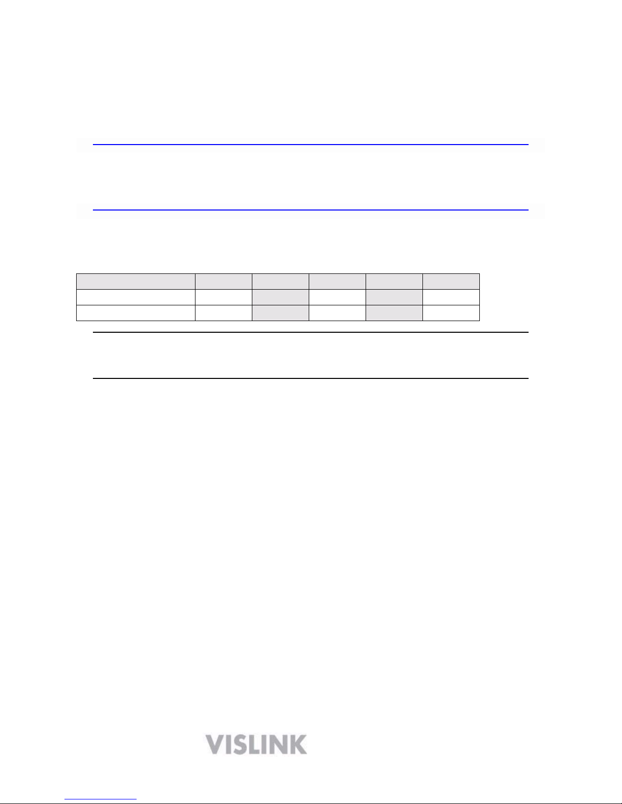
The HDX-1100, operated without an antenna will not create RF energy exceeding 1.0 mW/cm2,
the FCC limit for exposure. Connecting an antenna to the unit greatly enhances the potential for
harmful exposure, and you must maintain a certain distance from the radiator. The following
table shows the Maximum Permissible Exposure (MPE) safe distances from the antenna.
Antenna Gain (dB1)
0
2 3 5 11
Safe Distance (cm)
4
6
6
8
15
Safe Distance (in) 1.57 2.36 2.36 3.15
5
.
9
Note Hazardous RF radiation limits and recommended distances may vary by
country. Observe all applicable state and federal regulations when using this
transmitter.
To perform calculations to understand the safe exposure margin (MPE), use the following
formula suggested by OET 65. The calculations provided are for common antennas often used
in the mobile microwave environment.
Calculating MPE
EIRP = P * (10 ^ (G / 10)) = (antilog of G/10) * P
P = RF power delivered to the antenna in mW
G = Power gain of the antenna in the direction of interest relative to an isotropic radiator
R = distance to the center of radiation of the antenna in centimeters
S = MPE in mW/cm² (milliwatts per square centimeters)
Conversions
dBi to numeric gain = Antilog (dBi/10)
Feet to centimeters = Feet * 30.48
Centimeters to Feet = cm * .0328
4 π = 12.57
User Input
RF power delivered to the antenna = Watts
Antenna gain (referenced to isotropic antenna) = dBi
Distance from the center of radiation = Feet
Calculation steps:
1. [P] RF power input. Watts to milliwatts = Watts * 1000
2. [G] Antenna gain dBi. Numeric gain = Antilog (dBi/10)
3. [EIRP] Multiply P * G
3
4. [R] Centimeters to feet = Centimeters * .0328
5. Square R
6. Multiply R² * 4
π
7. [S] Divide (R² * 4π ) into EIRP
S = Power Density in milliwatts per square centimeters.
Note At frequencies above 1500 MHz, S must not be greater than 1.
Reference
FCC OET Bulletin 65, August 1997 - Evaluating Compliance with FCC Guidelines for Human
Exposure to Radio Frequency Electromagnetic Fields
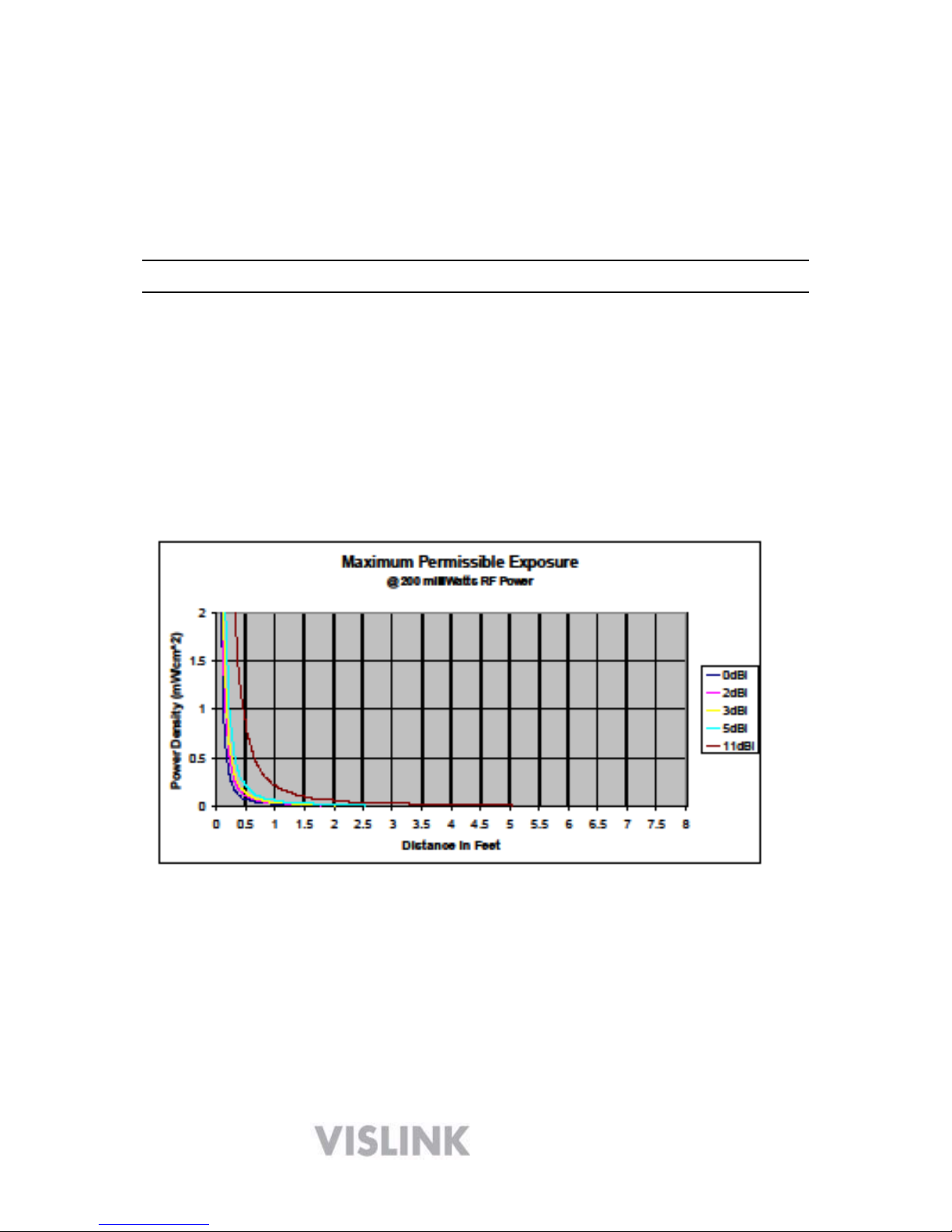
The figure below is a typical graph for a Vislink HDX-1100 Transmitter and shows the
permissible exposure distance for various antenna gains. Graphs and data will vary, based
on the actual transmitter, output power, frequency, and antenna utilized. One plot provides
the permissible output of the transmitter for digital modulation, and the other plot for analog
modulation.
Vislink, in accordance with the requirements set forth by the FCC, provides this information as a
guide to the user and assumes the users of this equipment are licensed and qualified to operate
the equipment per the guidelines and recommendations contained within the product user
guides and in accordance with any FCC rules that may apply.
4
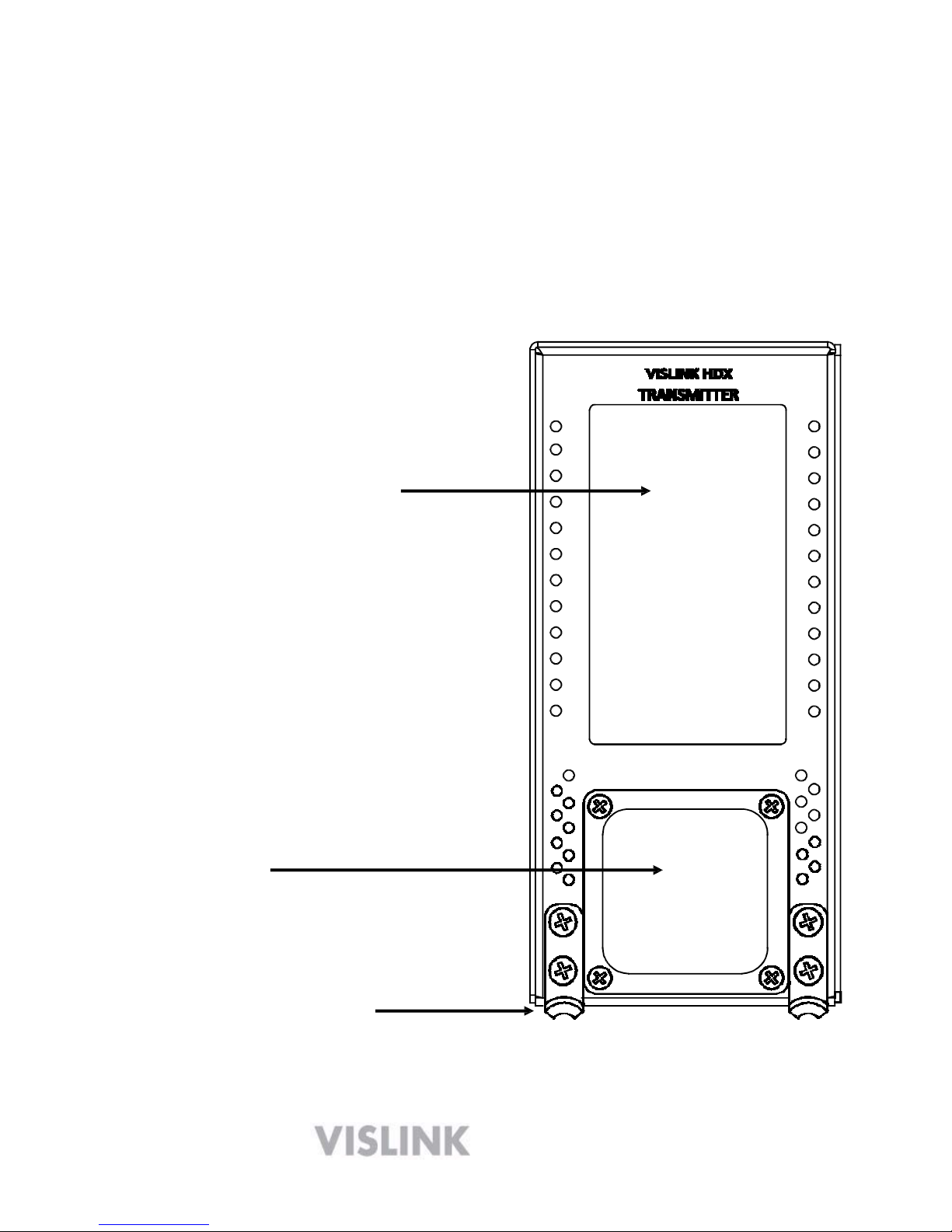
3 Installing an HDX-1100 Transmitter
The HDX-1100 is built in an ARINC compliant 3/8 ATR housing, and was designed primarily
for aircraft operation. It is also suitable for general mobile applications, including terrestrial
vehicles. The transmitter and its remote control panel (RCU) have been tested and certified to
be compliant with RTCA DO-160F, as recognized by the FAA and other global agencies that
regulate aircraft operation and safety. NOTE: Aircraft installation must be performed by
certified aircraft maintenance personnel.
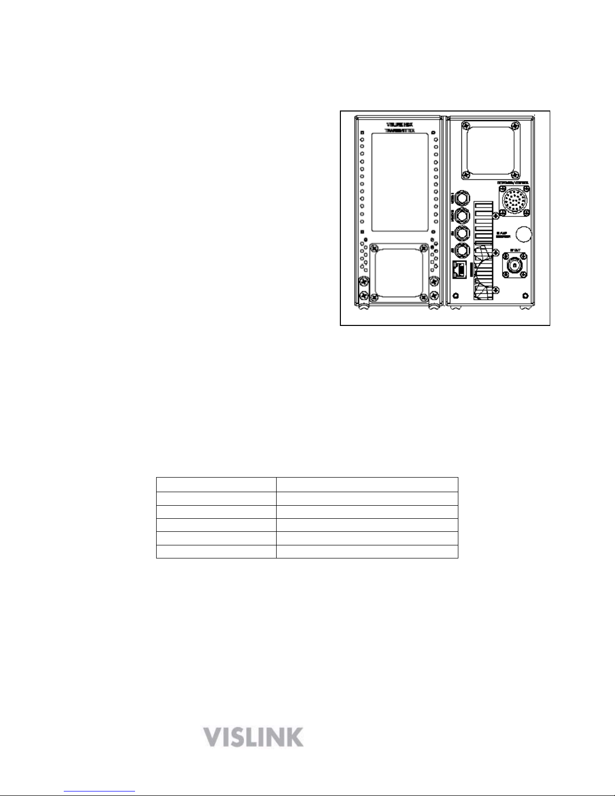
TOUCH SCREEN DISPLAY
AIR VENT
HOLD DOWN BRACKETS
(used with optional mounting kit)
HDX-1100 FRONT PANEL

5
DC POWER, AUDIO, DATA, REMOTE
VIDEO 1 – COMPOSITE NTSC or PAL
VIDEO 2 – COMPOSITE NTSC or PAL
SDI or HD-SDI DIGITAL VIDEO INPUT
10
ASI INPUT FROM EXT. ENCODER
WEB BROWSER MANAGEMENT
(Ethernet)
DC CIRCUIT BREAKER
RF OUTPUT
HDX-1100 REAR PANEL
The following electrical connections will be found on the rear panel of the HDX-1100.
o Video Inputs and connector types:
Video 1: BNC female –
NTSCorPALcomposite
Video 2 - BNC female – NTSCorPALcomposite(NOTE: This is the DoubleVision input,
usable in MPEG-4 SD mode only)
SDI: BNC female - SDI or HD-SDI (configurable)
ASI input: BNC female – accepts signal from an external encoder
o RJ-45 jack
10/100 web browser interface for set-up & maintenance
o RF Output: Type N female – 50 Ohms
o DC power in, audio, auxiliary data, and remote control, are all connected via 26 pin Bendix chassis
receptacle. A mating connector is supplied with each unit, and must be wired per the drawing in
section 7.3
6
NOTE: There is a 10 AMP DC circuit breaker on rear panel of HDX-1100. If the power to this
breaker is fed from another circuit breaker in the aircraft, the HDX-1100 breaker should be left in
the on position. To operate the breaker: push in = ON, pull out = OFF, a manual reset is required
after the breaker trips.
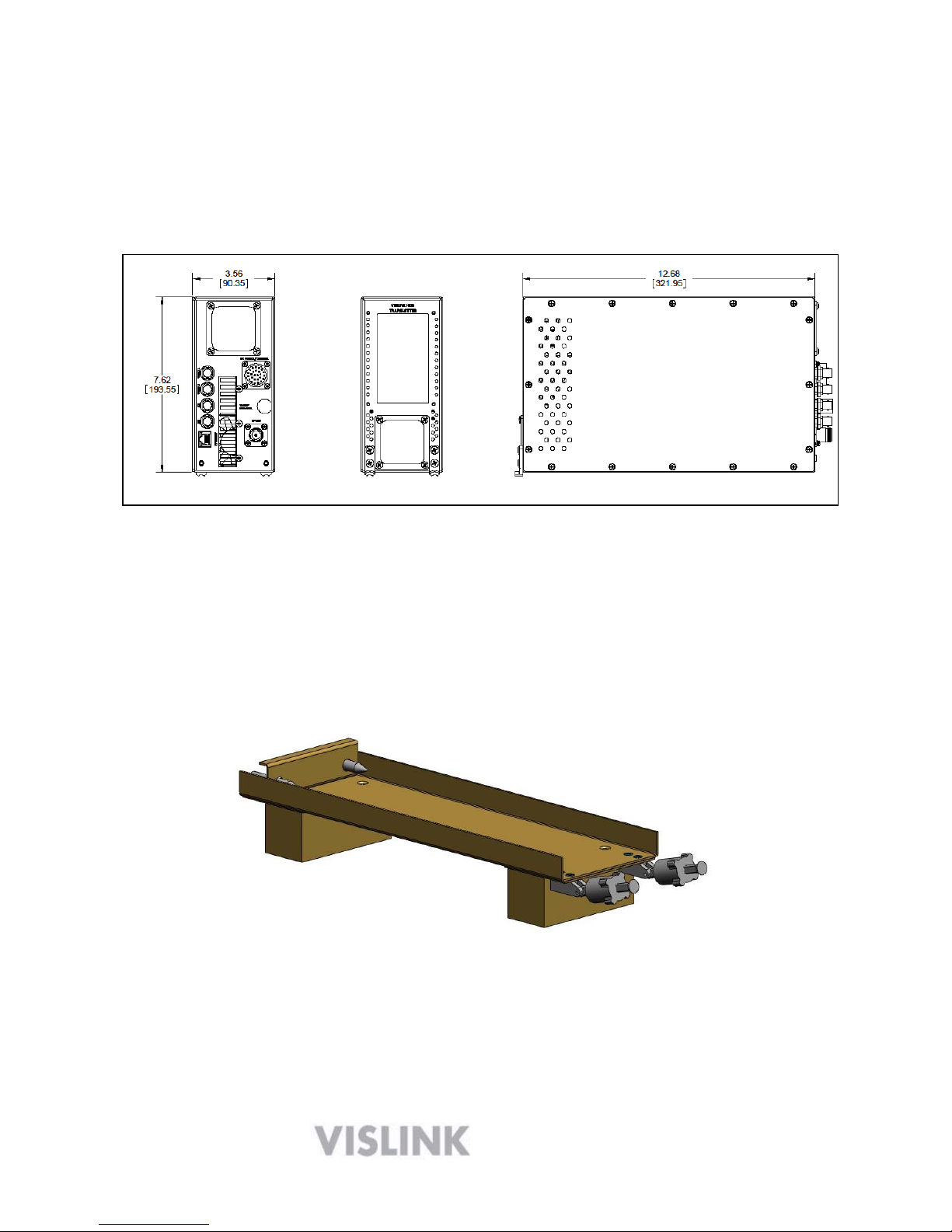
HDX-1100 MECHANICAL OUTLINE
An optional aircraft mounting kit (part # 9000372) may be ordered. The kit includes an ARINC
compliant low profile tray with quick release clamps, and removable spacers. This kit should
provide an installer with enough flexibility to satisfy most situations.
Please contact the factory if alternative mounting hardware is required.
Optional 9000372 3/8 ATR mounting kit with removable spacers

7
HDX-1100 installed in optional 3/8 ATR mounting tray with spacers
The optional 9000372 3/8 ATR mount includes a set of spacers that may be installed if
clearance is not sufficient to allow the clamps to disengage. The spacers would not be needed
if the mounting plate is attached to a shelf within the airframe, as shown below.
HDX-1100 in optional 3/8 ATR tray installed on existing shelf without spacers

8
4 Controlling the HDX-1100 with the Touch Panel
The touch panel screen on the front of the unit lets you perform routine setup and
maintenance functions and control the HDX-1100 directly as described in the following
sections.
4.1 Selecting a Preset or a Channel
The HDX-1100 recalls the most recently saved preset and channel when it is powered up.
You can select from up to nine preset configurations. All presets are set to a customer
supplied plan, or to standard factory defaults, which may changed to suit your needs. Up to
15 RF channels may be configured. To select a preset, do the following:
1. Press the UP or DOWN buttons below the PRESET bar in the display
2. The new PRESET selection will remain so until it is changed.
3. Press the UP or DOWN buttons below the CHANNEL bar in the display
4. The new CHANNEL selection will remain so until it is changed.
4.2 Selecting the RF Output Level
The HDX-1100 recalls the most recently saved RF output power level when it is powered up. To
select between high or low power for the RF output level, do the following:
1. Press PA HIGH/LOW key to toggle between HIGH or LOW RF output level.
2. Press the PA ON/OFF button to toggle between RF on and RF off.
NOTE: When changing channels or presets, the PA will automatically shut off to avoid
interference with other users, as the frequency changes. It must be manually turned on
again once the frequency change is complete (the display will change to new channel
selection).
Please refer to section 8 for complete information on using the local touch screen controller

9
5 Setting the HDX-1100 with the Aircraft Remote Panel
You can install the Aircraft remote control unit (RCU) up to 50 feet from the HDX-1100 using a
3-wire serial interconnection and a power source. The following figure shows the RCU.
Remote Control Unit – Part Number
907621-6
NOTE: Both the HDX-1100 touch screen and the RCU remote panel are active and capable of
control when the RCU is powered on. Information shown on the touch screen will update
dynamically if settings on the RCU are changed. Information shown on the RCU WILL NOT
update if settings are changed on the touch screen. The Indications may be re-synchronized by
initiating any change with the RCU, i.e. – preset, channel, etc.
The following table provides detailed descriptions of the functionality of each push button and
rotary switch, plus an explanation of each LED. Presets and channel numbers are both
shown in LCD window displays.

10
Function Name Description
Push Buttons RF ON
/
OFF Swi
t
ches the t
r
ansmitte
r
RF output be
t
ween standby (STBY) and
transmit (XMIT) conditions. In STBY, the RF output is zero.
BRIGHTNESS Sets the display b
r
ightness to high (H), low (L), or automatic
(A; light sensing).
LED Displays STBY Indicates the HDX-1100 is in s
t
andby mode
(No RF output; unit is powered but not transmitting).
XMIT Indicates the HDX-1100 is in t
r
ansmit mode.
DC OK Indicates DC Powe
r
is applied to the Remote Cont
r
ol Panel and
transmitting.
F
A
ULT Indicates an er
r
o
r
condition in the HDX-1100 transmitte
r
.
HI Indicates the HDX-1100 is in high RF output mode.
LO Indicates the HDX-1100 is in low RF output mode.
ENCRYPTION Indicates the HDX-1100is transmitting an encrypted signal
V
IDEO Indicates the presence of a video signal at the HDX input
Ro
t
ary
Switches RF HI/LOW Sets the HDX-1100 to high (HI) or low (LO) RF power output
mode.
PRESET Select from 1 to 9 presets.
CH
A
NNEL Select from 1 to 15 channels
LCD Display PRESET Displays the cu
r
r
ent p
r
eset numbe
r
.
CH
A
NNEL Displays the cu
r
r
ent channel numbe
r
.
Use a 9-pin RS-232 null-modem cable to connect the communication path between the RCU
and the HDX-1100.
A receptacle at the rear of the controller supplies DC power to the RCU. Vislink provides the
2-pin Weidmuller connector (Part # 52104-2) to connect to the power receptacle at the rear of
the controller. The required power range is from +10—+50 Vdc (negative ground only).
NOTE: During initial power up, the RCU will display a C until the HDX-1100 processor
completes a boot up and self check sequence; this is normal. If the C does not disappear
within one to two minutes, the HDX-1100 has lost power or a communications error has
occurred; check the circuit breakers, and power and serial cable connections.
To facilitate updating or servicing an HDX-1100 transmitter, we recommend that the
transmitter and RCU panel are fed from different circuit breakers. In normal operation, power
should be applied to the RCU first, or to both units simultaneously.
11
6 Configuring the internal HDX-1100 with a PC
The HDX-1100 is based on the ultra-portable Vislink HDT-1000 transmitter that has been
integrated with additional components and subsystems needed to provide a high performance
airborne or mobile transmission system. All Presets of HDX-1000 are programmed with factory
defaults representing typical video settings that may be used as they are, or modified to suit your
specific operating requirements. A list of factory presets is included with each transmitter.
WARNING: Do not attempt to modify, delete, or create new pre-sets until you have a
complete understanding of the video set-up menus described below. If you have any
questions in this regard, please contact Vislink customer service.
To set up the HDX-1100 transmitter with a PC, do the following:
1. Connect a LAN cable to the network connection of a router or switch and the ethernet
port on the HDX-1100.
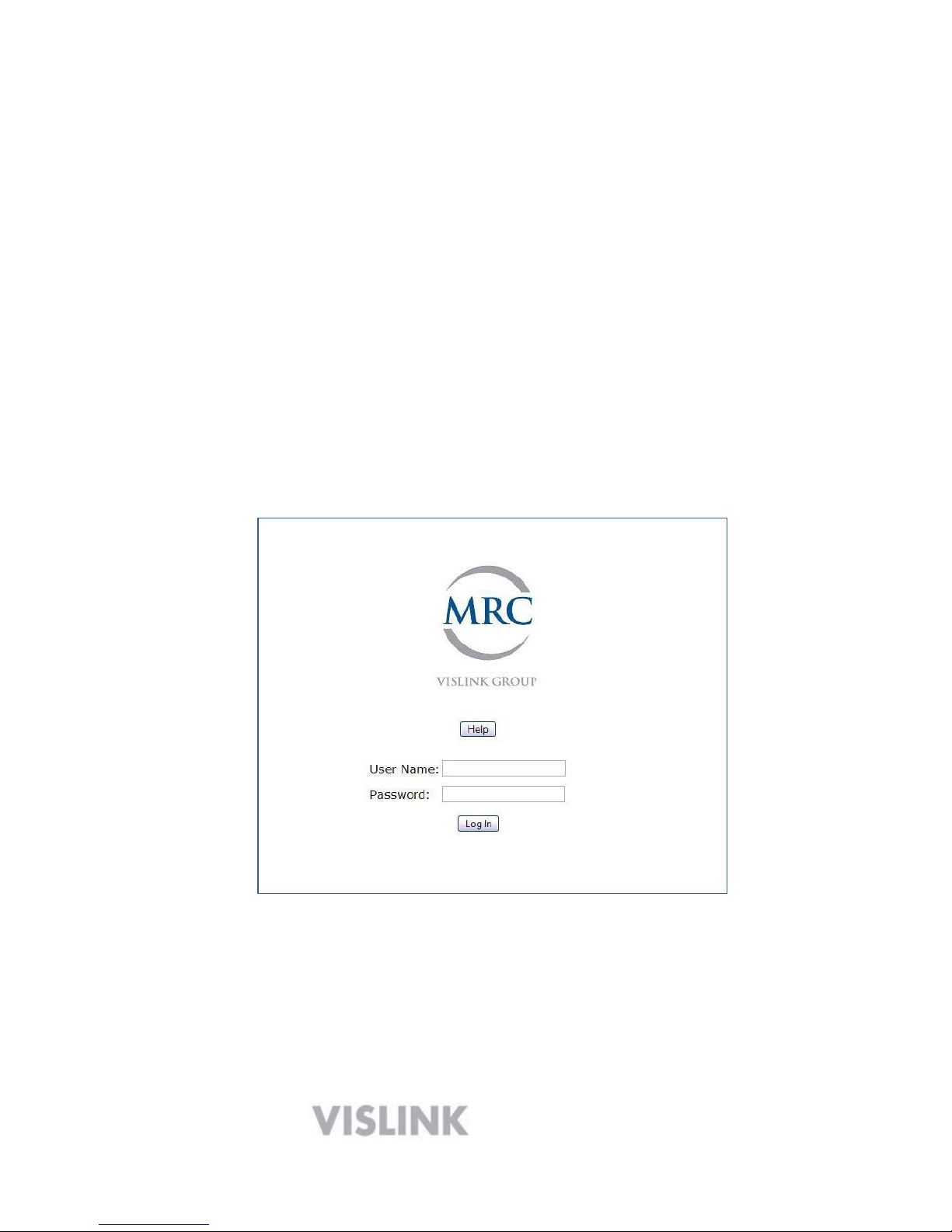
2. Open a web browser on your PC and type 192.168.1.150 into the URL address field
and press Enter. The screen will change to the HDX-1100 log-in page, as shown
below.
The factory defaults are: User Name = admin
Password = admin
NOTE: The factory default user name and password should be changed immediately
to prevent unauthorized access. A new user name and password should be
recorded and stored in a safe place.

12
6.1 MAIN SCREEN:
After the login procedure is complete, the browser will open to the MAIN SCREEN, providing a
view of operating conditions for the currently active pre-set. A drop down menu on the pre-set
line allows you to change to any available pre-set and review the parameters for each pre-set.
Changes to pre-sets CANNOT be made from this screen of the browser. The information on
the MAIN SCREEN of the browser is the same as the information on the main screen of HDX-
1100 touch panel.
WEB BROWSER - MAIN SCREEN
STATUS SCREEN:
The STATUS screen allows you to review the following:
Radio serial number, software revision, and network settings
MPEG-2 encoder setup
H.264/ MPEG-4 encoder setup
T o v i e w , c l i c k o n
―
S t a t u s
‖
i
n the bar at the top of the screen, and a dro
p down section will appear. Select which of the status items you wish to
review and all of the viewable parameters will be summarized in a column
on the left side of the screen.

13
In the screen shot below,
―
R a d i o
‖ h a
s b e e n s e l e c t e d f r o m t h e d r o p d o w
n
menu bar on the top, a n d
―
S / W r e v i s i o n
‖ h a
s b e e n s e l e c t e d f r o m t h e m e n
u
choices on the left side of the screen. The display shows all of the
software revisions currently installed in the HDX-1100.
MAIN SCREEN – STATUS TAB - SOFTWARE REVISION DISPLAY
6.2 SETUP SCREEN:
The SETUP screen is the only screen in the web browser utility that allows
the HDX-1100 to be programmed initially, or allows changes to be made in
existing programming. The SETUP screen allows qualified maintenance
personnel to program new presets and edit existing presets.
14
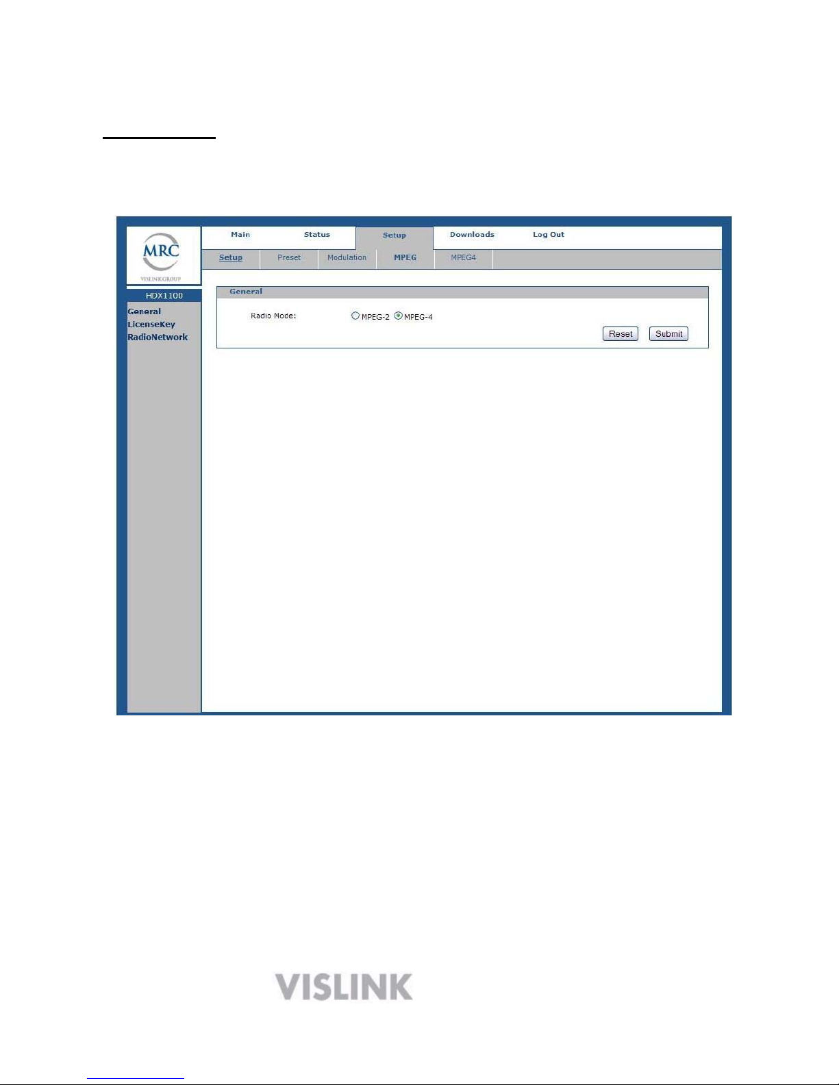
Initial Setup: C l i c k o n t h e w o r d
―
S e t u p
‖ i
n m e n u b a r a t t h e t o p o f t h
e
display. In the main area of the display, the General Setup screen will open
as shown below.
GENERAL SETUP SCREEN
In the example above, theH.264 encoding mode is active for the current
preset. It may be changed to MPEG 2 by clicking on the MPEG-2 dot, and
then clicking the submit button. IMPORTANT: If the radio mode is
changed, you must save a new or existing to preset to complete the
process.
NOTE: If your HDX-1100 is not equipped with the MPEG-2 option, this
choice will not be clickable.
IMPORTANT: When RESET and SUBMIT buttons are present in a setup
screen, the SUBMIT button is used to enter new data into the program

15
while the RESET button will cancel any programming action currently
16
entered, but not yet submitted. Clicking the RESET will return you to
the previous screen.
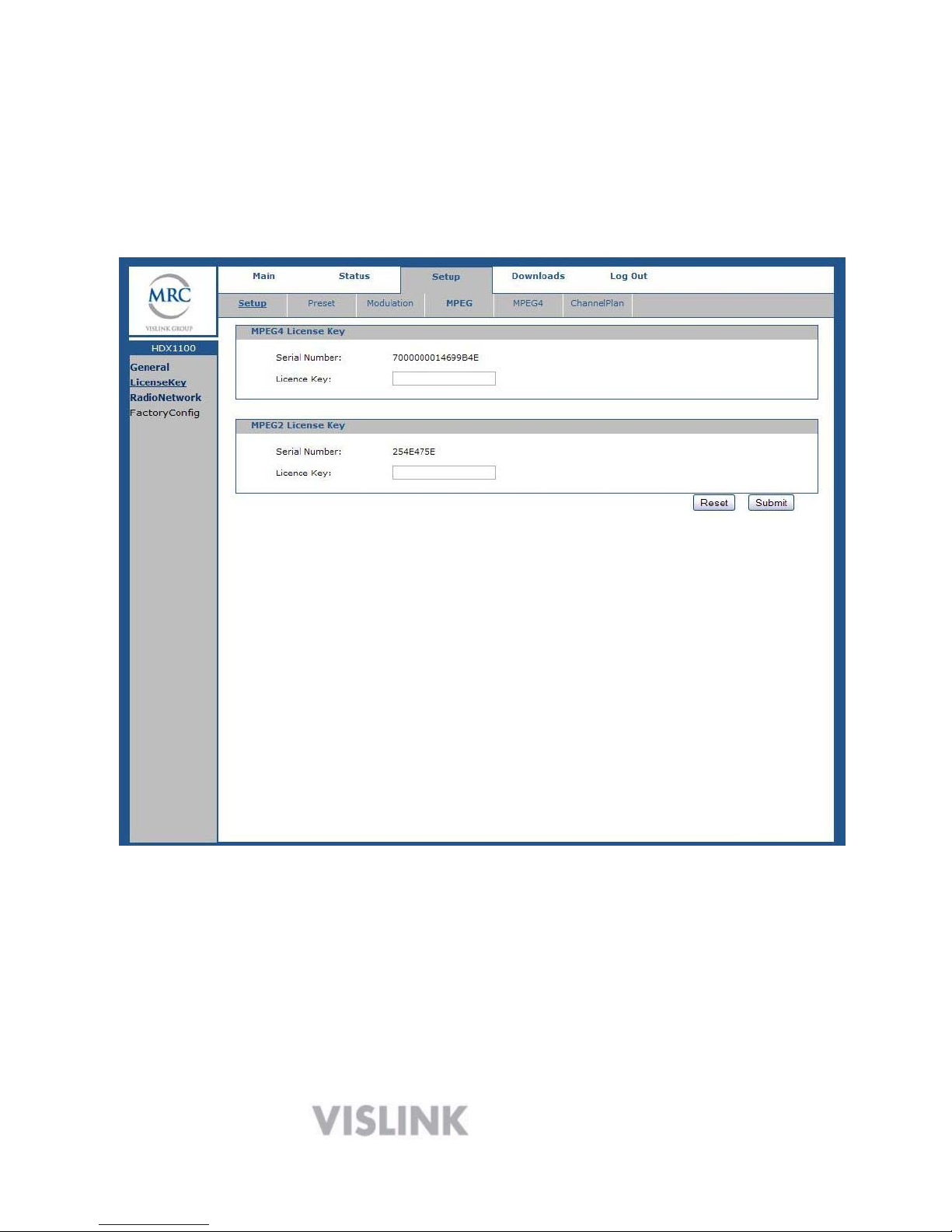
To view the HDX-1100 serial number, or re-enter the license key, select
License Key in the column on the left side of the display, and the screen
below will appear:
License Key Screen
The Serial Numbers are entered at the factory, and are always visible in
the space provided. The License Keys are never visible, except when they
are being entered at the factory, or reentered in the field after a repair has
been made. In both cases the License Key numbers will disappear as soon
as the submit button is pushed. The License Key number is provided to the
customer along with the factory data.

17
6.3 Radio Network Screen:
The values initially found in the IP address, Subnet, and Gateway dialog
boxes of the radio network screen are factory defaults. These should be
changed to match your specific network requirements. Changes are
accomplished by entering the new values in the dialog boxes then clicking
on the submit button. If an error is made during the entry process, simply
click the reset button to return to the previous screen, from which the
process can be restarted.
SETUP - RADIO NETWORK SCREEN
18
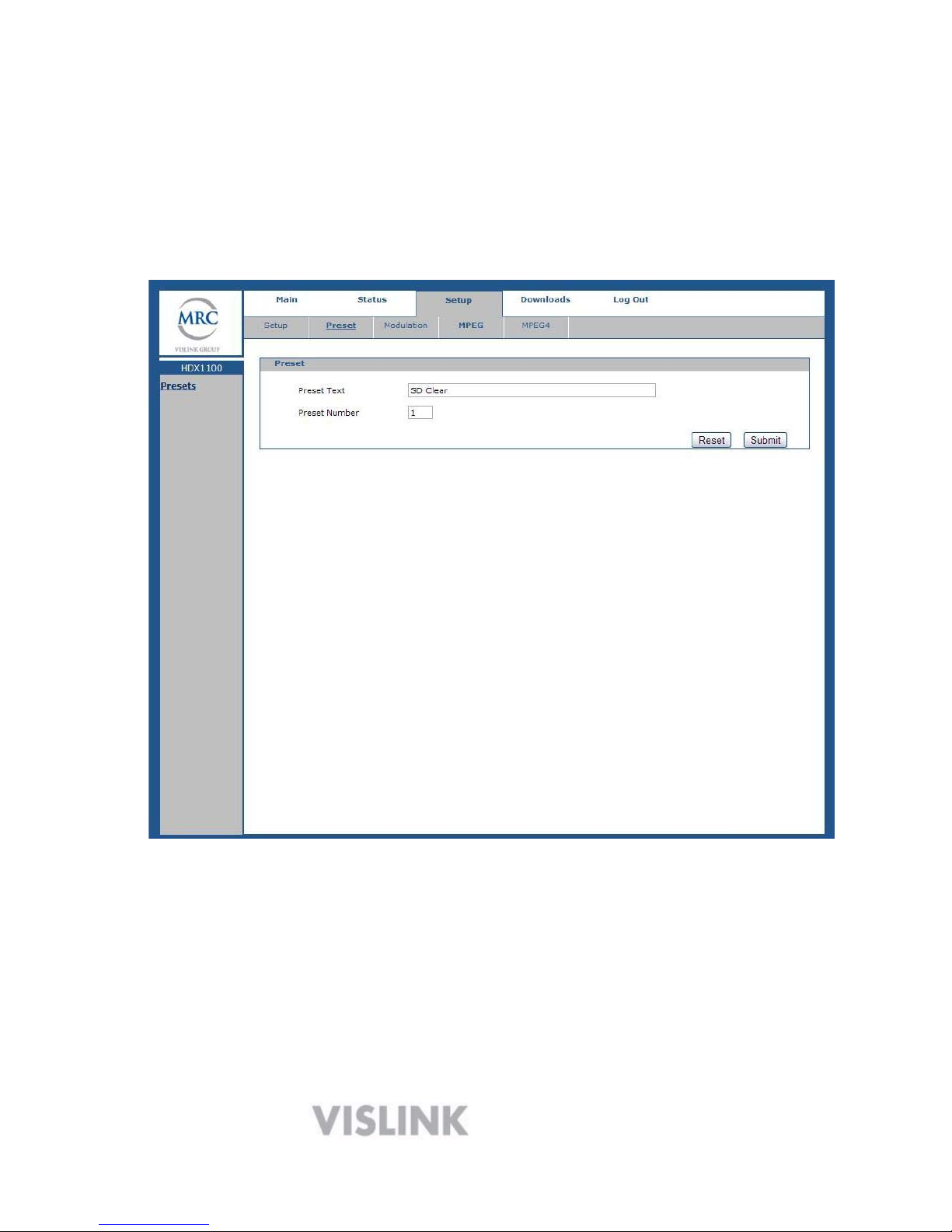
6.4 CONFIGURING PRESETS
For maximum flexibility, a complete set of parameters must be defined
for each preset that is programmed into the HDX-1100. To begin the
process, select Preset from the drop-down menu in the bar at the top of
the display, and the screen shown below will appear.
PRESET SCREEN
The Preset Text box accepts user input to identify each preset is. Text is
entered by the user for each preset, and saved with the Submit button.
To initiate programming or make a change, click on Preset Number and
choose the preset you wish to program or change from the drop down
menu. Enter the new text in the Preset Text dialog box, and click the
Submit button when you are satisfied with the result. Next, click on the
Modulation button in the menu bar at the top of the screen.
Table of contents
Other Vislink Transmitter manuals


