Waveshare RS232/485 TO WIFI POE ETH (B) User manual


RS232/485 TO WIFI POE ETH (B) User Manual
www.waveshare.com
2
1. OVERVIEW
Features:
Support 802.11b/g/n wireless standard.
Supports fast networking protocol.
Support router and bridge modes.
Supports communication via RS232/485 to WiFi and Ethernet interfaces.
Rich status indicator: PWR, LINK, RXD, TXD.
Wide-range voltage DC 6-36V input, supporting screw terminals, power supply and PoE Ethernet
port power supply.
The operating modes can be selected as transparent transmission mode, serial command mode,
HTTP Client Mode, Modbus mode, and AT command mode.
Support registering MAC, transparent cloud, and customized registration packets.
Supports custom heartbeat packets, socket distribution protocols, and Modbus polling functions.
Support timeout reboot, timed reboot function and so on.
Support MQTT function, can access Ali cloud and other IoT cloud platforms.
Support hardware watchdog, making the system more stable.
Supports serial port free framing and automatic framing, resulting in higher forwarding
efficiency.
Support Websocket function to achieve real-time interaction between serial ports and web
pages.
Support four parameter configuration methods: web page, software settings, serial AT command,
and network AT command.
Supports one click (pressing the RELOAD button for more than 5 seconds) to restore factory
settings.
Long communication distance, with two serial servers transmitting 150 meters to each other.
Guide rail design for easy and convenient installation.

RS232/485 TO WIFI POE ETH (B) User Manual
www.waveshare.com
3
CATALOGUE
1. Overview ................................................................................................................................................2
2. Quick get start ....................................................................................................................................... 6
2.1 Hardware Connection ..................................................................................................................6
2.2 network connections ...................................................................................................................7
2.3 Data transmission test .................................................................................................................9
3. Overview ..............................................................................................................................................10
3.1 Introduction ...............................................................................................................................10
3.2 Electrical parameter .................................................................................................................. 10
3.3 Product appearance .................................................................................................................. 11
3.4 Operating indicator and key ......................................................................................................12
3.5 Interface description ................................................................................................................. 13
3.6 Outline dimensions ....................................................................................................................14
3.7 Application scenarios .................................................................................................................15
4. Product Parameters Setting ................................................................................................................ 16
4.1 Web management page ............................................................................................................ 16
4.1.1 Open the management page ..........................................................................................16
4.1.2 Quick configuration page ............................................................................................... 17
4.1.3 Mode selection page ...................................................................................................... 18
4.1.4 Wireless access point settings page ............................................................................... 18
4.1.5 Wireless terminal settings page ..................................................................................... 19
4.1.6 Serial port and network settings page ........................................................................... 20
4.1.7 Ethernet function settings ..............................................................................................22
4.1.8 HTTPDClient mode page .................................................................................................22
4.1.9 MQTT function settings page ......................................................................................... 24
4.1.10 Module Management Page ..........................................................................................25
4.2 Software configuration ..............................................................................................................26
4.2.1 Download link .................................................................................................................26
4.2.2 Software introduction .................................................................................................... 26

RS232/485 TO WIFI POE ETH (B) User Manual
www.waveshare.com
4
5. Product networking application .......................................................................................................... 28
5.1 Wireless networking settings .................................................................................................... 28
5.2 Wireless networking applications ............................................................................................. 31
5.2.1 Wireless Networking Applications (AP) ..........................................................................31
5.2.2 Wireless networking application (STA) .......................................................................... 32
5.2.3 Wireless networking application (AP+STA) .................................................................... 33
5.2.4 Wireless networking application (AP, STA) .................................................................... 35
5.3 Wired networking setup ............................................................................................................36
5.4 Wired networking application ...................................................................................................38
5.4.1 Wired networking application (APLAN) ......................................................................... 38
5.4.2 Wired networking application (APWAN) ........................................................................38
5.4.3 Wired networking application (routing) .........................................................................40
5.4.4 Wired networking application (bridge) .......................................................................... 41
6. Product function description ...............................................................................................................42
6.1 Working mode ........................................................................................................................... 42
6.1.1 Transparent transmission mode .................................................................................... 42
6.1.2 Serial command mode ....................................................................................................43
6.1.3 HTTPDCLIENT mode ........................................................................................................45
6.1.4 ModbusTCP<=>ModbusRTU conversion mode ............................................................. 55
6.2 Wireless characteristics .............................................................................................................56
6.2.1 Automatic frequency selection function ........................................................................56
6.2.2 Security mechanism ....................................................................................................... 56
6.2.3 STA joins the routing function ........................................................................................57
6.2.4 STA address binding function .........................................................................................57
6.3 Socket communication .............................................................................................................. 57
6.4 UART framing mechanism ......................................................................................................... 58
6.4.1 Serial Parameters ........................................................................................................... 58
6.4.2 UART Free-Frame Mode .................................................................................................59
6.4.3 UART automatic framing mode ......................................................................................60

RS232/485 TO WIFI POE ETH (B) User Manual
www.waveshare.com
5
6.5 Password authentication when TCP establishes connection ....................................................61
6.6 Description of RFC2217 protocol .............................................................................................. 62
6.7 Fast Networking Protocol ..........................................................................................................64
6.8 Local area network search .........................................................................................................66
6.9 Registration packet function ..................................................................................................... 67
6.10 Customized heartbeat packets ................................................................................................68
6.11 Socket distribution function .................................................................................................... 70
6.12 Timeout reboot function ......................................................................................................... 73
6.13 Timed reboot function ............................................................................................................ 73
6.14 Modbus polling ........................................................................................................................73
6.15 KeepALIVE Function .................................................................................................................74
6.16 Websocket function ................................................................................................................ 74
6.17 MQTT function .........................................................................................................................74
6.17.1 MQTT function introduction ........................................................................................ 74
6.17.2 RS232/485 TO WIFI POE ETH (B) Parameter Configuration .........................................75

RS232/485 TO WIFI POE ETH (B) User Manual
www.waveshare.com
6
2. QUICK GET START
The RS232/485 TO WIFI POE ETH (B) serial server supports the functions of UART to WIFI, UART
to Ethernet, and Ethernet to WIFI. It can convert the RS485 serial port into a TCP/IP network interface
and achieve bidirectional transparent data transmission between the RS485 serial port and
WIFI/Ethernet.
This chapter provides a quick start introduction for the RS232/485 to WiFi POE ETH (B) serial
server. We recommend users to seriously read this chapter and follow the instructions step by step.
This will give you a comprehensive understanding of the product. Users can also choose to read
specific chapters based on their interests and needs. For specific details and explanations, please refer
to the following chapters.
This section primarily provides a quick start guide for the RS232/485 TO WIFI POE ETH (B) device
in AP mode.
The following software is involved: SSCOM.exe: Serial Debugging Assistant.
2.1 HARDWARE CONNECTION
The default configuration for RS232/485 to WiFi POE Ethernet (B) is as follows:
Figure RS232/485 TO WIFI POE ETH (B) default configuration
In order to test the communication conversion of RS232/485 to WiFi/Ethernet, we will connect
the serial port of the RS232/485 to WiFi POE Eth (B) serial server to the serial port of the computer.

RS232/485 TO WIFI POE ETH (B) User Manual
www.waveshare.com
7
Additionally, the WiFi of the serial server will be connected to the WiFi of the computer. If the
desktop does not have its own serial port and WIFI, it can be replaced by USB TO RS232/485/422/TTL
and wireless network card. Hardware connection diagram as shown below:
Figure Hardware Connection
According to the above figure, simply connect the antenna, power supply, and RS232 or RS485
cable to the serial server interface according to the label instructions.
2.2 NETWORK CONNECTIONS
Let's take WIFI connection as an example to introduce the network connection process.
Open the wireless network connection and search for the network. As shown in the figure below,
"Waveshareuxxxx" (xxxx is the last four digits of the MAC address) is the default network name (SSID)
for the serial server.


RS232/485 TO WIFI POE ETH (B) User Manual
www.waveshare.com
9
Figure Wireless Network Connection
At this point, the Link indicator on the module changes from flashing once every 1 second to
flashing once every 2 seconds.
2.3 DATA TRANSMISSION TEST
The initial parameters for RS232/485 to WiFi POE Ethernet (B) are as follows:
The default SSID is "Waveshare_xxxx" ("xxxx" represents the last four digits of the module's MAC
address).
The default encryption method is "open” and “none”.
The default user serial parameters: 57600,8,1,None;
The default value of network parameters: TCP,Server,8899,10.10.100.254;
Local IP address: 10.10.100.254
We just need to follow the appropriate parameter settings for network communication, and
then bidirectional communication between the serial port and Wi-Fi can be achieved. The operation
steps are as follows:
Open the testing software "SSCOM.exe". Connect to the computer's COM5 (select the
appropriate port based on your situation). Choose the RS232/485 TO WIFI ETH (B) serial server's
default baud rate of 57600, and click "Open Port".
Open another instance of "SSCOM.exe". In the network settings section, choose TCP Client mode.
Enter the server IP address as 10.10.100.254, which is the default IP address of the module. Enter the
server port number as 8899, which is the default TCP port number the module listens on. Click
"Connect" to establish a TCP connection.
By now, we can test data transmission between the serial ports and network:
Data flow from the serial port to the network:
Computer serial port → RS232/485 TO WIFI POE ETH (B) serial port → WIFI/Ethernet of
RS232/485 TO WIFI POE ETH (B) → Computer network.
The data flow from the network to the serial port is:
Computer network -> RS232/485 TO WIFI POE ETH (B) WiFi/Ethernet -> RS232/485 TO WiFi POE
ETH (B) serial port -> Computer serial port. The specific demonstration is shown in the following
figure:

RS232/485 TO WIFI POE ETH (B) User Manual
www.waveshare.com
10
Figure Serial port/network transmission test
3. OVERVIEW
3.1 INTRODUCTION
The RS232/485 TO WIFI POE ETH (B) serial server supports UART-to-Wi-Fi, allowing you to
convert a serial port (RS232 or RS485) into a TCP/IP network port. This enables bidirectional
transparent data transmission between the serial interface (RS232 or RS485) and Wi-Fi. This enables
serial devices to immediately have TCP/IP network interface functions, connect to the network for
data communication, greatly expanding the communication distance of serial devices, as shown in the
following figure:
Figure Basic functions of serial server
Users do not need to worry about specific details. The module completes protocol conversion
internally, and can achieve bidirectional data transmission between the serial port and WIFI through
simple settings.
3.2 ELECTRICAL PARAMETER
Table Electrical Parameters
Name
Item
Index
Wireless
standards
802.11b/g/n
Frequency range
2.412GHz-2.484GHz
Transmitting
power
802.11b:+19dBm(Max.@11Mbps)
802.11g:+18dBm(Max.@54Mbps)

RS232/485 TO WIFI POE ETH (B) User Manual
www.waveshare.com
11
WIRELESS
SPECIFICATION
+17dBm(Max.@HT20,MCS7)
+17dBm(Max.@HT40,MCS7)
Configured by users
Receiving
sensitivity
802.11b:-89dBm(@11Mbps)
802.11g:-81dBm(@54Mbps)
802.11n:-73dBm(@HT20,MCS7)
-71dBm(@HT40,MCS7)
HARDWARE
SPECIFICATION
Data port
RS232, RS485: 300~460.8Kbps
RS232 port(ESD/EFT protection)
RS232 port(ESD/EFT/surge protection)
Network port
Ethernet: 10Mbps/100Mbps
Operating
voltage
DC6~36V
Operating
temperature
-40℃~85℃
Dimensions
109.66*28*64.71mm(L*W*H)
Software
parameters
Wireless network
Station/AP/AP+Station mode
Security
mechanism
WPA PSK/WPA2 PSK
Encryption type
TKIP/AES
Operating mode
transparent transmission mode, protocol
transmission mode
Command setting
AT+Command Structure
Protocol
TCP/UDP/ARP/ICMP/DHCP/DNS/HTTP/MQTT
Maximum TCP
connections
24
User
Configuration
Web Server+AT Command Configuration
Customer
application
software
Support customer customization of application
software
3.3 PRODUCT APPEARANCE
The following image shows the appearance of RS232/485 TO WIFI ETH (B):

RS232/485 TO WIFI POE ETH (B) User Manual
www.waveshare.com
12
Figure Product Appearance
3.4 OPERATING INDICATOR AND KEY
There are 4 indicator on the device, from left to right they are:
Indicator
Function
Note
RXD
Receiving data
Blinks when the serial port of the device
receives data
TXD
Sending data
The device flashes when sending data through
the serial port.
LINK
Operating indicator
Network connection
The green indicator remains off and blinks once
every 1 second. During firmware upgrades, it
blinks once every 0.5 seconds. Once a WiFi
connection is established, the blinking pattern
changes to once every 2 seconds.
PWR
Power indicator
Always on when power input is correct
RELOAD key:
This button is the Factory Reset button. To perform a factory reset while the device is in its
normal operational state (indicated by the flashing Link LED), press and hold the button for at least 5
seconds, then release it. Wait for about 10 seconds, and the RS232/485 TO WIFI POE ETH (B) device
will automatically complete the reset process. During this process, all indicator lights except the PWR

RS232/485 TO WIFI POE ETH (B) User Manual
www.waveshare.com
13
indicator will turn off, and then the Link LED will begin flashing again. This will indicate that the
device's settings have been restored to their factory configuration.
3.5 INTERFACE DESCRIPTION
The hardware interfaces are as follows:
Antenna connector: 3dbi antenna.
Ethernet port: RJ45 interface.
RS232 interface: DB9 male interface. See the above figure for the cable sequence.
RS232/485 TO WIFI POE ETH (B) User Manual
www.waveshare.com
14
RS485 interface: RS485 interface, which is A, B and G from right to left according to the logo.
Power interface (terminal): 5.08*2P terminal power interface. The product power input has TVS
and anti-reverse connection protection, and supports wide voltage range: 6~36V power supply.
Power interface (DC jack): DC 5.5 jack, supporting wide voltage range: 6~36V power supply.
RJ45 network port: RS232/485 TO WIFI POE ETH(B) supports PoE Ethernet power supply.
The connection of the network port, the network port of the module is 10M/100M adaptive,
supporting AUTOMDI/MDIX, which means that you can use the direct network cable to directly
connect with the computer for testing. The RS232/485 TO WIFI POE ETH (B) serial server disables the
network port by default, and can be enabled by AT command or webpage setting if it is necessary to
use the network port.
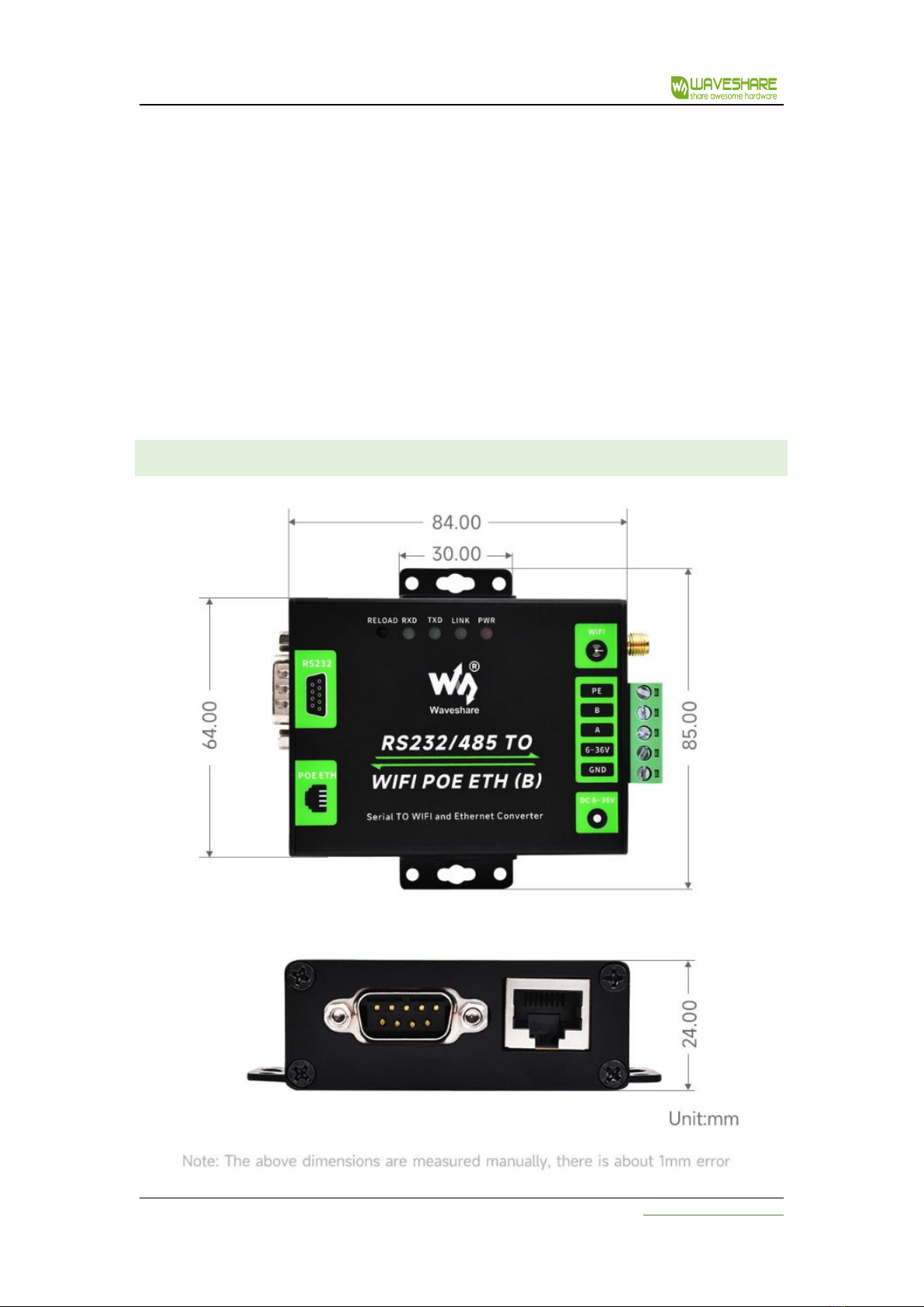
3.6 OUTLINE DIMENSIONS

RS232/485 TO WIFI POE ETH (B) User Manual
www.waveshare.com
15
Figure Outline dimensions
3.7 APPLICATION SCENARIOS
The application scenarios of RS232/485 to WiFi/Ethernet is as shown below:
The seial port (RS232/485) to WiFi ETH (B) are as follows:
WiFi remote control/monitor, TCP/ip and WiFi co-processor.
WIFI remote control in the field of toys such as airplanes and cars.
WIFI network radio, camera, digital photo frame;
Medical instrument, data acquisition device, handheld devices.
Wi-Fi body fat scale, smart card terminal and smart home.
Instruments and meters, equipment parameter monitoring, wireless POS machine;
Other wireless related secondary development and application in modern agriculture and
military fields;
Smart factories, smart homes, smart medical care and other fields.

RS232/485 TO WIFI POE ETH (B) User Manual
www.waveshare.com
16
4. PRODUCT PARAMETERS SETTING
The RS232/485 TO WIFI POE ETH (B) serial server supports AT command and Web parameter
setting. For the setting of AT command, please refer to the chapter of "AT instruction set" in the
document. This chapter mainly explains how to set up the Web.
4.1 WEB MAN AGEMENT PAGE
When using RS232/485 TO WIFI POE ETH (B) serial server for the first time, it is necessary to
configure the WIFI serial server. You can connect the AP interface of RS232/485 TO WIFI POE ETH (B)
through a PC and configure it with a web management page.
By default, the AP interface SSID of RS232/485 TO WIFI POE ETH (B) is Waveshare_xxxx, and the
IP address, user name and password are as follows:
Table Network Default Settings
Specifications
Default
SSID
Waveshare_xxxx
IP Address
10.10.100.254
subnet mask
255.255.255.0
user name
admin
password
admin
4.1.1 OPEN THE MANAGEMENT PAGE
Firstly, connect RS232/485 TO WIFI POE ETH (B) with the wireless network card of PC, and the
SSID is Waveshare_xxxx. When connected, open the browser, enter 10.10.100.254 in the address bar
and press enter. Fill in the user name and password in the pop-up dialog box, and then "confirm".
Figure the second step of opening the management web page
Then; The RS232/485 TO WIFI POE ETH (B) management page supports Chinese and English, and
can be set in the upper right corner. It is divided into 9 pages, namely, quick configuration, mode

RS232/485 TO WIFI POE ETH (B) User Manual
www.waveshare.com
17
selection, wireless access point settings, wireless terminal settings, serial port and network settings,
Ethernet function settings, HTTPDClient mode, advanced settings and module management.
4.1.2 QUICK CONFIGURATION PAGE
Figure Quick Setup Page
The quick configuration page provides a method for users to quickly configure RS232/485 TO
WIFI POE ETH (B) serial server. After configuring the parameters according to the steps on the page
and restarting the WIFI serial server, the WIFI serial server can work normally, which reduces the
steps and time of configuration. Of course, there are fewer options on this page, and the detailed
configuration should be configured on the corresponding page.
This page has five options to configure and a restart item, which are explained below:
WIFI Setting: configure the working mode of WIFI, AP or STA mode.
Ethernet Ports Setting: Enable/disable Ethernet port and set corresponding working mode.
UART Setting: configure serial port parameters, including serial port baud rate, parity bit, 485
function and so on.
Network Setting: configure network parameters, only related parameters of SocketA.
MQTT setting: configure MQTT enabling and MQTT connection server related parameters.

RS232/485 TO WIFI POE ETH (B) User Manual
www.waveshare.com
18
Device management: When all the above parameters are configured, click Restart to restart the
module.
4.1.3 MODE SELECTION PAGE
The first page of the Web can be set to select RS232/485 TO WIFI POE ETH (B) serial server to
work in AP mode or STA mode.
"Data transmission mode" the working modes of WIFI serial server are transparent transmission
mode, serial command mode, HTTPDClient mode and ModbusTCP<=>ModbusRTU mode.
Figure wireless mode settings
4.1.4 WIRELESS ACCESS POINT SETTINGS PAGE
RS232/485 TO WIFI POE ETH (B) supports AP interface, through which the WIFI serial server can
be managed very conveniently, and the self-organizing network can be realized. The management
page is shown below. Including the setting of SSID, wireless network mode and wireless security, and
the setting of local area network composed of AP.

RS232/485 TO WIFI POE ETH (B) User Manual
www.waveshare.com
19
Figure Access point settings
4.1.5 WIRELESS TERMINAL SETTINGS PAGE
Wireless terminal interface, also known as STA interface. RS232/485 TO WIFI POE ETH (B) can be
connected to other wireless networks through the STA interface, as shown in the following figure:
The settings on this page include two tables. The top one is the wireless settings for STA,
including the SSID of the AP to be connected, security settings, etc. The following table shows the
network connection mode settings, including DHCP and static connection mode.

RS232/485 TO WIFI POE ETH (B) User Manual
www.waveshare.com
20
Figure Wireless Terminal Interface Settings
4.1.6 SERIAL PORT AND NETWORK SETTINGS PAGE
Application program settings refer to the settings of WIFI to serial port application parameters,
including serial port parameter settings, automatic framing settings, Ethernet function settings, device
registration package settings, and network protocol settings.
Serial Port and Network Parameter Settings
This manual suits for next models
1
Table of contents
Other Waveshare Network Hardware manuals


