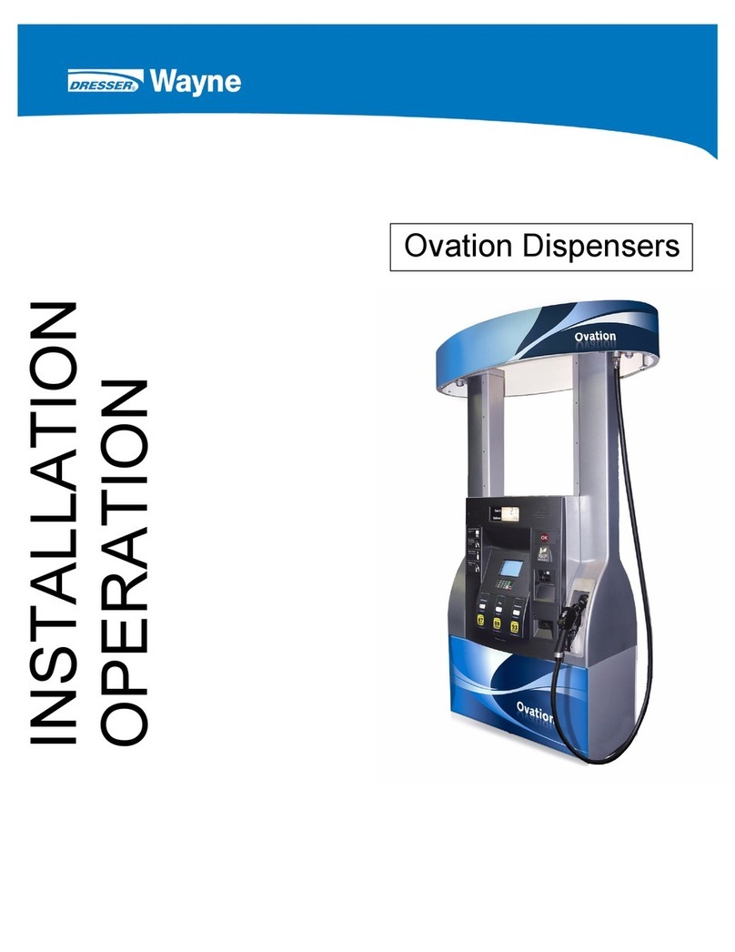
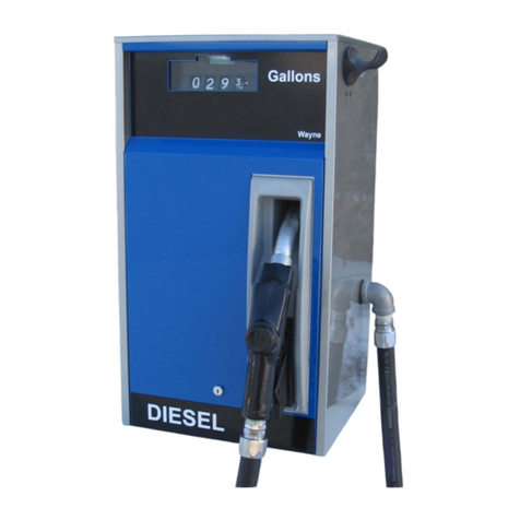
Wayne Dresser Vista 1 Series User manual

1/Vista Series
Blending and
Non-Blending
Remote
Dispensers
SERVICE

READTHIS MANUAL BEFORE YOU BEGIN SERVICING THE DISPENSER
Dispensers have both electricity and a hazardous, flammable and potentially explosive liquid. Fail-
ure to follow the Warning and Caution instructions in this manual, may result in hazardous condi-
tion. Follow all rules, codes and laws that apply to your area and installation.
SAFETY PRECAUTIONS - OPERATION
Make sure that you know how to turn OFF power to the dispenser and submersible pumps in an
emergency. Repair all leaks or defects immediately.
SAFETY PRECAUTIONS - INSTALLATION AND MAINTENANCE
Always make sure ALL power to the dispenser is turned OFF before you open the dispenser cab-
inet for maintenance. Physically lock, restrict access to, or tag the circuit breakers you turn off
when servicing the dispenser. Be sure to trip (close) the emergency valve(s) under the dispenser
BEFORE beginning maintenance.
EQUIPMENT PRECAUTIONS
Be sure to bleed all air from product lines of remote dispensers and prime suction pumps before
dispensing product. Always use the approved method for lifting the dispenser. Never lift by the
nozzle, sheet metal, valance, etc.
HOWTO CONTACTWAYNE
Technical assistance is available at Wayne Technical Support (1-800-926-3737).
INDICATORS AND NOTATIONS
Danger indicates a hazard or unsafe practice which, if not avoided, will
result in severe injury or possibly death.
Warning indicates a hazard or unsafe practice which, if not avoided, may
result in severe injury or possibly death.
Caution indicates a hazard or unsafe practice which, if not avoided, may
result in minor injury.
Note:
Important information to consider, otherwise, improper installation,
operation, and/or damage to components may occur.
WARNING
!
DANGER
!
WARNING
!
CAUTION
!

February 1997 Part No. 920160 Rev A
1/Vista Series Blending and
Non-Blending Remote
Dispensers
Service Manual

Part No. 920160 Rev A February 1997

iii
February 1997 Part No. 920160 Rev. A
TABLE OF CONTENTS
Title Page
1. INTRODUCTION . . . . . . . . . . . . . . . . . . . . . . . . . . . . . . . . . . . . . . . . . . . . . . . . . . . . . . . . . . . . . . . . . 1
2. GENERAL OPERATION . . . . . . . . . . . . . . . . . . . . . . . . . . . . . . . . . . . . . . . . . . . . . . . . . . . . . . . . . . . 3
2.1. Sequence of the Dispensing Cycle (Non-Blenders) . . . . . . . . . . . . . . . . . . . . . . . . . . . . . . . 3
2.1.1. Lift-to-Start Models. . . . . . . . . . . . . . . . . . . . . . . . . . . . . . . . . . . . . . . . . . . . . . . . 3
2.1.2. Push-to-Start Models. . . . . . . . . . . . . . . . . . . . . . . . . . . . . . . . . . . . . . . . . . . . . . . 3
2.2. Sequence of the Dispensing Cycle (Blenders Only) . . . . . . . . . . . . . . . . . . . . . . . . . . . . . . . 4
2.3. Unit Prices/Authorization . . . . . . . . . . . . . . . . . . . . . . . . . . . . . . . . . . . . . . . . . . . . . . . . . . . 5
2.3.1. Manually Setting Unit Prices . . . . . . . . . . . . . . . . . . . . . . . . . . . . . . . . . . . . . . . . 5
2.3.2. Authorize Switch. . . . . . . . . . . . . . . . . . . . . . . . . . . . . . . . . . . . . . . . . . . . . . . . . . 8
2.3.3. Setting A Fueling Point (Pump Number) . . . . . . . . . . . . . . . . . . . . . . . . . . . . . . . 8
2.4. The Blending Process . . . . . . . . . . . . . . . . . . . . . . . . . . . . . . . . . . . . . . . . . . . . . . . . . . . . . . 9
3. ELECTRONIC PARTS . . . . . . . . . . . . . . . . . . . . . . . . . . . . . . . . . . . . . . . . . . . . . . . . . . . . . . . . . . . . 13
3.1. Display Boards. . . . . . . . . . . . . . . . . . . . . . . . . . . . . . . . . . . . . . . . . . . . . . . . . . . . . . . . . . . 13
3.2. Lighted Cash/Credit Interface Board. . . . . . . . . . . . . . . . . . . . . . . . . . . . . . . . . . . . . . . . . . 13
3.3. Solenoid Drive Board . . . . . . . . . . . . . . . . . . . . . . . . . . . . . . . . . . . . . . . . . . . . . . . . . . . . . 14
3.4. Computer Assembly . . . . . . . . . . . . . . . . . . . . . . . . . . . . . . . . . . . . . . . . . . . . . . . . . . . . . . 15
3.4.1. Fault Codes . . . . . . . . . . . . . . . . . . . . . . . . . . . . . . . . . . . . . . . . . . . . . . . . . . . . . 18
3.5. Fault Reporting . . . . . . . . . . . . . . . . . . . . . . . . . . . . . . . . . . . . . . . . . . . . . . . . . . . . . . . . . . 18
3.6. Intrinsic Safe Barrier Assembly. . . . . . . . . . . . . . . . . . . . . . . . . . . . . . . . . . . . . . . . . . . . . . 22
3.7. Pulser Assembly . . . . . . . . . . . . . . . . . . . . . . . . . . . . . . . . . . . . . . . . . . . . . . . . . . . . . . . . . 24
3.7.1. Photocoupler . . . . . . . . . . . . . . . . . . . . . . . . . . . . . . . . . . . . . . . . . . . . . . . . . . . . 24
3.7.2. Pulser Disc. . . . . . . . . . . . . . . . . . . . . . . . . . . . . . . . . . . . . . . . . . . . . . . . . . . . . . 24
3.8. Proportional Flow Control Valve . . . . . . . . . . . . . . . . . . . . . . . . . . . . . . . . . . . . . . . . . . . . 26
4. MECHANICAL PARTS . . . . . . . . . . . . . . . . . . . . . . . . . . . . . . . . . . . . . . . . . . . . . . . . . . . . . . . . . . . 27
4.1. Nozzle Boot (Proximity “Reed” Switch Style Boot). . . . . . . . . . . . . . . . . . . . . . . . . . . . . . 27
4.1.1. Lift-to-Start Version . . . . . . . . . . . . . . . . . . . . . . . . . . . . . . . . . . . . . . . . . . . . . . 27
4.1.2. Push-to-Start Version . . . . . . . . . . . . . . . . . . . . . . . . . . . . . . . . . . . . . . . . . . . . . 27
5. HYDRAULIC PARTS. . . . . . . . . . . . . . . . . . . . . . . . . . . . . . . . . . . . . . . . . . . . . . . . . . . . . . . . . . . . . 29
5.1. Strainer and Filter . . . . . . . . . . . . . . . . . . . . . . . . . . . . . . . . . . . . . . . . . . . . . . . . . . . . . . . . 29
5.1.1. Strainer . . . . . . . . . . . . . . . . . . . . . . . . . . . . . . . . . . . . . . . . . . . . . . . . . . . . . . . . 29
5.1.2. Filter . . . . . . . . . . . . . . . . . . . . . . . . . . . . . . . . . . . . . . . . . . . . . . . . . . . . . . . . . . 29
5.2. Two Stage Solenoid Valve (Non-Blenders only) . . . . . . . . . . . . . . . . . . . . . . . . . . . . . . . . 30
5.2.1. Flow Control Valve “Off” No Flow . . . . . . . . . . . . . . . . . . . . . . . . . . . . . . . . . . 31
5.2.2. Flow Control Valve “On” Slow Flow. . . . . . . . . . . . . . . . . . . . . . . . . . . . . . . . . 31
5.2.3. Flow Control Valve “On” Full Flow. . . . . . . . . . . . . . . . . . . . . . . . . . . . . . . . . . 31
5.3. Proportional Flow Control Valve (Blenders Only) . . . . . . . . . . . . . . . . . . . . . . . . . . . . . . . 36
5.3.1. Flow Control Valve “Off” No Flow . . . . . . . . . . . . . . . . . . . . . . . . . . . . . . . . . . 37
5.3.2. Flow Control Valve “On” Slow Flow. . . . . . . . . . . . . . . . . . . . . . . . . . . . . . . . . 38
5.3.3. Flow Control Valve “On” Full Regulated Flow . . . . . . . . . . . . . . . . . . . . . . . . . 38
5.4. Meter . . . . . . . . . . . . . . . . . . . . . . . . . . . . . . . . . . . . . . . . . . . . . . . . . . . . . . . . . . . . . . . . . . 38
5.4.1. Meter Adjustment . . . . . . . . . . . . . . . . . . . . . . . . . . . . . . . . . . . . . . . . . . . . . . . . 39
6. TROUBLESHOOTING GUIDE . . . . . . . . . . . . . . . . . . . . . . . . . . . . . . . . . . . . . . . . . . . . . . . . . . . . . 41

iv
Part No. 920160 Rev. A February 1997
TABLE OF CONTENTS,
continued
Title Page
7. COMPONENT REPLACEMENT. . . . . . . . . . . . . . . . . . . . . . . . . . . . . . . . . . . . . . . . . . . . . . . . . . . . 53
7.1. Electronic Component Replacement . . . . . . . . . . . . . . . . . . . . . . . . . . . . . . . . . . . . . . . . . . 53
7.1.1. Removing the Bezel From Vista Dispensers. . . . . . . . . . . . . . . . . . . . . . . . . . . . 54
7.1.2. DEM In Service Position. . . . . . . . . . . . . . . . . . . . . . . . . . . . . . . . . . . . . . . . . . . 54
7.1.3. Solenoid Drive Board Replacement . . . . . . . . . . . . . . . . . . . . . . . . . . . . . . . . . . 54
7.1.4. Computer Assembly Replacement . . . . . . . . . . . . . . . . . . . . . . . . . . . . . . . . . . . 56
7.1.5. Intrinsic Safe Barrier Assembly Replacement . . . . . . . . . . . . . . . . . . . . . . . . . . 58
7.1.6. Display Board Replacement . . . . . . . . . . . . . . . . . . . . . . . . . . . . . . . . . . . . . . . . 60
7.1.7. Cash/Credit Interface Board Replacement . . . . . . . . . . . . . . . . . . . . . . . . . . . . . 61
7.1.8. Photocoupler/Pulser Disc Replacement . . . . . . . . . . . . . . . . . . . . . . . . . . . . . . . 62
7.1.9. Lift-to-Start Nozzle Boot Component Replacement. . . . . . . . . . . . . . . . . . . . . . 64
7.1.10. Push-to-Start Nozzle Boot Component Replacement . . . . . . . . . . . . . . . . . . . . . 65
7.1.11. Push-to-Start Membrane Switch Assembly Replacement. . . . . . . . . . . . . . . . . . 68
7.1.12. Back Lit Display Lamp Replacement . . . . . . . . . . . . . . . . . . . . . . . . . . . . . . . . . 68
7.1.13. Electro-Mechanical Totalizer Replacement . . . . . . . . . . . . . . . . . . . . . . . . . . . . 69
7.2. Hydraulic Component Replacement . . . . . . . . . . . . . . . . . . . . . . . . . . . . . . . . . . . . . . . . . . 69
7.2.1. Diaphragm Replacement (Non-Blenders Only) . . . . . . . . . . . . . . . . . . . . . . . . . 69
7.2.2. Diaphragm Valve Replacement (Non-Blenders Only) . . . . . . . . . . . . . . . . . . . . 70
7.2.3. Actuator Replacement (Non-Blenders Only) . . . . . . . . . . . . . . . . . . . . . . . . . . . 70
7.2.4. Meter . . . . . . . . . . . . . . . . . . . . . . . . . . . . . . . . . . . . . . . . . . . . . . . . . . . . . . . . . . 71
7.2.5. Proportional Flow Control Valve Replacement (Blenders Only) . . . . . . . . . . . . 71
7.2.6. Check and Pressure Relief Valve Replacement . . . . . . . . . . . . . . . . . . . . . . . . . 71
APPENDIX A. TROUBLESHOOTING FLOWCHARTS . . . . . . . . . . . . . . . . . . . . . . . . . . . . . . . . . . 73
APPENDIX B. SERVICE INFORMATION AND CONNECTOR PIN OUTS. . . . . . . . . . . . . . . . . 101
B.1. Dispenser Electronic Module (DEM) . . . . . . . . . . . . . . . . . . . . . . . . . . . . . . . . . . . . . . . . 102
APPENDIX C. WIRING DIAGRAMS. . . . . . . . . . . . . . . . . . . . . . . . . . . . . . . . . . . . . . . . . . . . . . . . 125
WARRANTY AND LIMITATION OF REMEDY AND LIABILITY. . . . . . . . . . . . . . Inside Back Cover
FCC WARNING . . . . . . . . . . . . . . . . . . . . . . . . . . . . . . . . . . . . . . . . . . . . . . . . . . . . . . . . . . . . .Back Cover
LIST OF FIGURES
Title Page
Figure 2-1. Function Switches and Display Locations - Non Blender Shown . . . . . . . . . . . . . . . . . . . 6
Figure 2-2. Unit Price Display . . . . . . . . . . . . . . . . . . . . . . . . . . . . . . . . . . . . . . . . . . . . . . . . . . . . . . . 6
Figure 2-3. Proportional Blending . . . . . . . . . . . . . . . . . . . . . . . . . . . . . . . . . . . . . . . . . . . . . . . . . . . 10
Figure 2-4. Fixed Ratio Blending . . . . . . . . . . . . . . . . . . . . . . . . . . . . . . . . . . . . . . . . . . . . . . . . . . . . 11
Figure 3-1. Computer and Solenoid Drive Board (Non-Blender). . . . . . . . . . . . . . . . . . . . . . . . . . . . 16
Figure 3-2. Computer and Solenoid Drive Board (Blender). . . . . . . . . . . . . . . . . . . . . . . . . . . . . . . . 17
Figure 3-3. Fault Code Display. . . . . . . . . . . . . . . . . . . . . . . . . . . . . . . . . . . . . . . . . . . . . . . . . . . . . . 19
Figure 3-4. Main Sale Display Showing Transaction Counters . . . . . . . . . . . . . . . . . . . . . . . . . . . . . 20
Figure 3-5. Main Sale Display Showing Transaction Counter and Fault Code . . . . . . . . . . . . . . . . . 20
Figure 3-6. Intrinsic Safe Barrier Assembly . . . . . . . . . . . . . . . . . . . . . . . . . . . . . . . . . . . . . . . . . . . . 23

v
February 1997 Part No. 920160 Rev. A
LIST OF FIGURES,
continued
Title Page
Figure 3-7. Non-Blending Photocoupler Internal Wiring. . . . . . . . . . . . . . . . . . . . . . . . . . . . . . . . . . 25
Figure 3-8. Blending Photocoupler Internal Wiring . . . . . . . . . . . . . . . . . . . . . . . . . . . . . . . . . . . . . . 25
Figure 5-1. Flow Control Valve “Off” No Flow. . . . . . . . . . . . . . . . . . . . . . . . . . . . . . . . . . . . . . . . . 32
Figure 5-2. Flow Control Valve “On” Slow Flow . . . . . . . . . . . . . . . . . . . . . . . . . . . . . . . . . . . . . . . 33
Figure 5-3. Flow Control Valve “On” Full Flow . . . . . . . . . . . . . . . . . . . . . . . . . . . . . . . . . . . . . . . . 34
Figure 5-4. Flow Control Valve With Cover and Center Chamber Removed . . . . . . . . . . . . . . . . . . 35
Figure 5-5. Proportional Flow Control Valve. . . . . . . . . . . . . . . . . . . . . . . . . . . . . . . . . . . . . . . . . . . 36
Figure 5-6. Meter Cutaway . . . . . . . . . . . . . . . . . . . . . . . . . . . . . . . . . . . . . . . . . . . . . . . . . . . . . . . . . 39
Figure 5-7. Meter Adjustment. . . . . . . . . . . . . . . . . . . . . . . . . . . . . . . . . . . . . . . . . . . . . . . . . . . . . . . 40
Figure 7-1. Replacing the Solenoid Drive Board (Non-Blender Shown) . . . . . . . . . . . . . . . . . . . . . . 55
Figure 7-2. Replacing the Duplex II Computer. . . . . . . . . . . . . . . . . . . . . . . . . . . . . . . . . . . . . . . . . . 57
Figure 7-3. Intrinsic Safe Barrier Assembly . . . . . . . . . . . . . . . . . . . . . . . . . . . . . . . . . . . . . . . . . . . . 59
Figure 7-4. Replacing the Intrinsic Safe Barrier Assembly . . . . . . . . . . . . . . . . . . . . . . . . . . . . . . . . 59
Figure 7-5. Replacing the Integrated Display Board. . . . . . . . . . . . . . . . . . . . . . . . . . . . . . . . . . . . . . 60
Figure 7-6. Replacing the Lighted Cash Credit Interface Board. . . . . . . . . . . . . . . . . . . . . . . . . . . . . 61
Figure 7-7. Exploded View Pulser Assembly. . . . . . . . . . . . . . . . . . . . . . . . . . . . . . . . . . . . . . . . . . . 63
Figure 7-8. Nozzle Boot Assembly (Lift-to-Start) . . . . . . . . . . . . . . . . . . . . . . . . . . . . . . . . . . . . . . . 66
Figure 7-9. Nozzle Boot Assembly (Push-to-Start) . . . . . . . . . . . . . . . . . . . . . . . . . . . . . . . . . . . . . . 67
Figure A-1. Fault Code 01 . . . . . . . . . . . . . . . . . . . . . . . . . . . . . . . . . . . . . . . . . . . . . . . . . . . . . . . . . . 74
Figure A-2. Fault Code 02 . . . . . . . . . . . . . . . . . . . . . . . . . . . . . . . . . . . . . . . . . . . . . . . . . . . . . . . . . . 75
Figure A-3. Fault Code 03 . . . . . . . . . . . . . . . . . . . . . . . . . . . . . . . . . . . . . . . . . . . . . . . . . . . . . . . . . . 76
Figure A-4. Fault Code 04 . . . . . . . . . . . . . . . . . . . . . . . . . . . . . . . . . . . . . . . . . . . . . . . . . . . . . . . . . . 77
Figure A-5. Fault Code 05 or 20 . . . . . . . . . . . . . . . . . . . . . . . . . . . . . . . . . . . . . . . . . . . . . . . . . . . . . 78
Figure A-6. Fault Code 06 . . . . . . . . . . . . . . . . . . . . . . . . . . . . . . . . . . . . . . . . . . . . . . . . . . . . . . . . . . 79
Figure A-7. Fault Code 08 . . . . . . . . . . . . . . . . . . . . . . . . . . . . . . . . . . . . . . . . . . . . . . . . . . . . . . . . . . 80
Figure A-8. Fault Code 09 . . . . . . . . . . . . . . . . . . . . . . . . . . . . . . . . . . . . . . . . . . . . . . . . . . . . . . . . . . 81
Figure A-9. Fault Code 10 or 21 . . . . . . . . . . . . . . . . . . . . . . . . . . . . . . . . . . . . . . . . . . . . . . . . . . . . . 82
Figure A-10. Fault Code 11 . . . . . . . . . . . . . . . . . . . . . . . . . . . . . . . . . . . . . . . . . . . . . . . . . . . . . . . . . . 83
Figure A-11. Fault Code 12 . . . . . . . . . . . . . . . . . . . . . . . . . . . . . . . . . . . . . . . . . . . . . . . . . . . . . . . . . . 84
Figure A-12. Fault Code 13 . . . . . . . . . . . . . . . . . . . . . . . . . . . . . . . . . . . . . . . . . . . . . . . . . . . . . . . . . . 85
Figure A-13. Fault Code 14 . . . . . . . . . . . . . . . . . . . . . . . . . . . . . . . . . . . . . . . . . . . . . . . . . . . . . . . . . . 86
Figure A-14. Fault Code 15 or 16 . . . . . . . . . . . . . . . . . . . . . . . . . . . . . . . . . . . . . . . . . . . . . . . . . . . . . 87
Figure A-15. Fault Code 30 . . . . . . . . . . . . . . . . . . . . . . . . . . . . . . . . . . . . . . . . . . . . . . . . . . . . . . . . . . 88
Figure A-16. Fault Code 31 . . . . . . . . . . . . . . . . . . . . . . . . . . . . . . . . . . . . . . . . . . . . . . . . . . . . . . . . . . 89
Figure A-17. Fault Code 51 . . . . . . . . . . . . . . . . . . . . . . . . . . . . . . . . . . . . . . . . . . . . . . . . . . . . . . . . . . 90
Figure A-18. Fault Code 54 . . . . . . . . . . . . . . . . . . . . . . . . . . . . . . . . . . . . . . . . . . . . . . . . . . . . . . . . . . 91
Figure A-19. Sale Display and Unit Price Displays are Blank . . . . . . . . . . . . . . . . . . . . . . . . . . . . . . . 92
Figure A-20. Displays Scrambled or Missing Segments . . . . . . . . . . . . . . . . . . . . . . . . . . . . . . . . . . . . 93
Figure A-21. Unit Will Not Respond to an Individual Function Switch . . . . . . . . . . . . . . . . . . . . . . . . 94
Figure A-22. Unit Will Not Respond to any Function Switches . . . . . . . . . . . . . . . . . . . . . . . . . . . . . . 95
Figure A-23. Displays are On but Unit Will Not Respond . . . . . . . . . . . . . . . . . . . . . . . . . . . . . . . . . . 96
Figure A-24. Dispenser Resets But Will Not Dispense Product . . . . . . . . . . . . . . . . . . . . . . . . . . . . . . 97
Figure A-25. Unit Price Showing 0.000. . . . . . . . . . . . . . . . . . . . . . . . . . . . . . . . . . . . . . . . . . . . . . . . . 98
Figure A-26. Electro-Mechanical Totalizer Not Counting . . . . . . . . . . . . . . . . . . . . . . . . . . . . . . . . . . 99

vi
Part No. 920160 Rev. A February 1997
LIST OF FIGURES,
continued
Title Page
Figure B-1. DEM Removal . . . . . . . . . . . . . . . . . . . . . . . . . . . . . . . . . . . . . . . . . . . . . . . . . . . . . . . . 102
Figure B-2. DEM in the Service Position . . . . . . . . . . . . . . . . . . . . . . . . . . . . . . . . . . . . . . . . . . . . . 103
Figure B-3. Computer and Solenoid Drive Board Connector Pinouts (Non-Blenders) . . . . . . . . . . 104
Figure B-4. Computer and Solenoid Drive Board Connector Pinouts (Proportional Blenders) . . . . 105
Figure B-5. Computer and Solenoid Drive Board Connector Pinouts (Fixed Ratio Blenders). . . . . 106
Figure B-6. Pinout Connections to Duplex Computer Board - J3. . . . . . . . . . . . . . . . . . . . . . . . . . . 107
Figure B-7. Pinout Connections to Duplex Computer Board - J9 and J10 . . . . . . . . . . . . . . . . . . . . 108
Figure B-8. Pinout Connections to Blender Solenoid Drive Board - J1 . . . . . . . . . . . . . . . . . . . . . . 109
Figure B-9. Pinout Connections to Blender Solenoid Drive Board - J2 . . . . . . . . . . . . . . . . . . . . . . 110
Figure B-10. Pinout Connections to Blender Solenoid Drive Board - J3 . . . . . . . . . . . . . . . . . . . . . . 111
Figure B-11. Pinout Connections to Blender Solenoid Drive Board - J4 . . . . . . . . . . . . . . . . . . . . . . 112
Figure B-12. Pinout Connections to Non- Blender Solenoid Drive Board - J1 and J2 . . . . . . . . . . . . 113
Figure B-13. Connector and Fuse Locations on Lighted Cash/Credit Interface Board. . . . . . . . . . . . 114
Figure B-14. Pinout Connections to Lighted Cash/Credit Interface Board - J4 . . . . . . . . . . . . . . . . . 115
Figure B-15. Pinout Connections to Lighted Cash/Credit Interface Board - J3 . . . . . . . . . . . . . . . . . 115
Figure B-16. Pinout Connections to Lighted Cash/Credit Interface Board - J6 . . . . . . . . . . . . . . . . . 116
Figure B-17. Pinout Connections to Lighted Cash/Credit Interface Board - J7 . . . . . . . . . . . . . . . . . 116
Figure B-18. Pinout Connections to Lighted Cash/Credit Interface Board - J10 . . . . . . . . . . . . . . . . 117
Figure B-19. Pinout Connections to Lighted Cash/Credit Interface Board - J5 . . . . . . . . . . . . . . . . . 117
Figure B-20. ISB Assembly Connection Pinouts for MGD . . . . . . . . . . . . . . . . . . . . . . . . . . . . . . . . 118
Figure B-21. ISB Assembly Connection Pinouts for Blender (Except X1/V590 6 Hose) . . . . . . . . . 120
Figure B-22. ISB Assembly Connection Pinouts for X1/V590 6 Hose . . . . . . . . . . . . . . . . . . . . . . . 122
LIST OF TABLES
Title Page
Table 2-1. Unit Price Switch Closure Definitions (Blenders) . . . . . . . . . . . . . . . . . . . . . . . . . . . . . . . 7
Table 2-2. Unit Price Switch Closure Definitions (Non-Blenders). . . . . . . . . . . . . . . . . . . . . . . . . . . 7
Table 3-1. Fault Codes, Status, and Description . . . . . . . . . . . . . . . . . . . . . . . . . . . . . . . . . . . . . . . . 21
Table 6-1. Sale and Unit Price Displays are Blank.. . . . . . . . . . . . . . . . . . . . . . . . . . . . . . . . . . . . . . 42
Table 6-2. Display Segments Fail to Operate During Reset Cycle.. . . . . . . . . . . . . . . . . . . . . . . . . . 42
Table 6-3. Unit Price Displaying 0.000. . . . . . . . . . . . . . . . . . . . . . . . . . . . . . . . . . . . . . . . . . . . . . . 42
Table 6-4. Unit Price Not Correctly Displayed. . . . . . . . . . . . . . . . . . . . . . . . . . . . . . . . . . . . . . . . . 43
Table 6-5. Unit Will Not Respond to any Function Switches. . . . . . . . . . . . . . . . . . . . . . . . . . . . . . 43
Table 6-6. Unit Will Not Respond to an Individual Function Switch. . . . . . . . . . . . . . . . . . . . . . . . 43
Table 6-7. Computer Will Not Reset. . . . . . . . . . . . . . . . . . . . . . . . . . . . . . . . . . . . . . . . . . . . . . . . . 43
Table 6-8. Computer Resets But Submersible Pump Does Not Come On.. . . . . . . . . . . . . . . . . . . . 44
Table 6-9. Computer Resets But Does Not Dispense Product. . . . . . . . . . . . . . . . . . . . . . . . . . . . . . 44
Table 6-10. Electro-Mechanical Totalizer Not Counting. . . . . . . . . . . . . . . . . . . . . . . . . . . . . . . . . . . 45
Table 6-11. Fault Code 01. . . . . . . . . . . . . . . . . . . . . . . . . . . . . . . . . . . . . . . . . . . . . . . . . . . . . . . . . . 45
Table 6-12. Fault Code 02. . . . . . . . . . . . . . . . . . . . . . . . . . . . . . . . . . . . . . . . . . . . . . . . . . . . . . . . . . 45
Table 6-13. Fault Code 03. . . . . . . . . . . . . . . . . . . . . . . . . . . . . . . . . . . . . . . . . . . . . . . . . . . . . . . . . . 46
Table 6-14. Fault Code 04. . . . . . . . . . . . . . . . . . . . . . . . . . . . . . . . . . . . . . . . . . . . . . . . . . . . . . . . . . 46

vii
February 1997 Part No. 920160 Rev. A
LIST OF TABLES,
continued
Title Page
Table 6-15. Fault Code 05 or 20.. . . . . . . . . . . . . . . . . . . . . . . . . . . . . . . . . . . . . . . . . . . . . . . . . . . . . 47
Table 6-16. Fault Code 06. . . . . . . . . . . . . . . . . . . . . . . . . . . . . . . . . . . . . . . . . . . . . . . . . . . . . . . . . . 48
Table 6-17. Fault Code 08. . . . . . . . . . . . . . . . . . . . . . . . . . . . . . . . . . . . . . . . . . . . . . . . . . . . . . . . . . 48
Table 6-18. Fault Code 09. . . . . . . . . . . . . . . . . . . . . . . . . . . . . . . . . . . . . . . . . . . . . . . . . . . . . . . . . . 48
Table 6-19. Fault Code 10 or 21.. . . . . . . . . . . . . . . . . . . . . . . . . . . . . . . . . . . . . . . . . . . . . . . . . . . . . 49
Table 6-20. Fault Code 11. . . . . . . . . . . . . . . . . . . . . . . . . . . . . . . . . . . . . . . . . . . . . . . . . . . . . . . . . . 49
Table 6-21. Fault Code 12. . . . . . . . . . . . . . . . . . . . . . . . . . . . . . . . . . . . . . . . . . . . . . . . . . . . . . . . . . 49
Table 6-22. Fault Code 13. . . . . . . . . . . . . . . . . . . . . . . . . . . . . . . . . . . . . . . . . . . . . . . . . . . . . . . . . . 49
Table 6-23. Fault Code 14, 15 or 16.. . . . . . . . . . . . . . . . . . . . . . . . . . . . . . . . . . . . . . . . . . . . . . . . . . 50
Table 6-24. Fault Code 30. . . . . . . . . . . . . . . . . . . . . . . . . . . . . . . . . . . . . . . . . . . . . . . . . . . . . . . . . . 50
Table 6-25. Fault Code 31. . . . . . . . . . . . . . . . . . . . . . . . . . . . . . . . . . . . . . . . . . . . . . . . . . . . . . . . . . 50
Table 6-26. Fault Code 51. . . . . . . . . . . . . . . . . . . . . . . . . . . . . . . . . . . . . . . . . . . . . . . . . . . . . . . . . . 51
Table 6-27. Fault Code 54. . . . . . . . . . . . . . . . . . . . . . . . . . . . . . . . . . . . . . . . . . . . . . . . . . . . . . . . . . 51
Table B-1. ISB Assembly Connection Pinouts for MGD . . . . . . . . . . . . . . . . . . . . . . . . . . . . . . . . 119
Table B-2. ISB Assembly Connection Pinouts for Blender (except X1/V590 6 Hose) . . . . . . . . . 121
Table B-3. ISB Assembly Connection Pinouts for X1/V590 6 Hose . . . . . . . . . . . . . . . . . . . . . . . 123

viii
Part No. 920160 Rev. A February 1997

1
February 1997 Part No. 920160 Rev A
1. INTRODUCTION
ThismanualdescribestheserviceofWayneVista series blending and non-blending dispensers that
have a 1 in the prefix of the model number. For example, 1/V390D1/GQY. Again these dispensers
can be identified by their model which begins with “1/V”. The basic troubleshooting methods and
service theory will remain the same for all models of dispensers which satisfy the above definition.
Any information which is specific to a particular model of dispenser will be shown as specific in
the text.
Any service problems which cannot be solved should be referred to Wayne Technical Support or
to the appropriate regional service office.
Wayne Technical Support 1-800-926-3737
Austin, TX 24 hours/7 days
Northeast Regional 410-546-6750
Service Office 8:30AM-5:00 PM Eastern
Salisbury, MD
Southeast Regional 770-988-3362
Service Office 8:30AM-5:00PM Eastern
Atlanta, GA
North Central Regional 312-693-7404
Service Office 8:30AM-5:00PM Central
Chicago, IL
South Central Regional 713-987-5442
Service Office 8:30AM-5:00PM Central
Houston, TX
Southwest Regional 714-952-1137
Service Office 8:30AM-5:00PM Pacific
Cypress, CA
Northwest Regional 510-328-0400
Service Office 8:30AM-5:00PM Pacific
San Ramon, CA
Mid-Atlantic Regional 410-691-2200
Service Office 8:30AM-5:00PM Eastern
Baltimore, MD
INTERNATIONAL OFFICES
Caribbean and Latin America (Voice) 410-546-6757
Service Office (FAX) 410-548-6968
Salisbury, MD
Mid-East and Africa (Voice) 44-1635-874881
Service Office (FAX) 44-1635-876633
United Kingdom
Far East (Voice) 65-734-4431
Service Office (FAX) 65-737-0219
Singapore

2
Part No. 920160 Rev A February 1997

3
February 1997 Part No. 920160 Rev A
2. GENERAL OPERATION
The general operation is very similar for all dispensers with model numbers beginning with 1/V.
2.1. SEQUENCE OF THE DISPENSING CYCLE (NON-BLENDERS)
2.1.1. Lift-to-Start Models
• When the nozzle is removed from the nozzle boot and the lever is lifted, the constant
+5 VDC that the computer supplies to the nozzle switch goes to ground. This signals
the computer to begin its reset cycle.
• When the dispenser receives an
Authorization
signal either from the control system
or from the Authorize switch in the dispenser, the correct submersible pump relay
will be energized.
*
• The computer performs a self test and flashes eights, blanks, then resets to zeros, on
the main sale display.
• The slow valve coil is energized two to six seconds, depending on option program-
ming settings, after the submersible pump relay is energized.
• After a small amount of fuel has been dispensed, the fast valve coil is switched on
and both coils are now energized together.
• In preset sales the fast coil is de-energized just prior to the final shut-off amount. The
slow valve coil is then de-energized when the final amount is reached.
• When the lever is lowered, the nozzle switch goes back to the constant +5 VDC, the
sale is complete, and the nozzle is returned to the nozzle boot.
2.1.2. Push-to-Start Models
• When the nozzle is removed from the nozzle boot, the constant +5 VDC that the
computer supplies to the nozzle switch goes to ground. At this point, one of the
lighted buttons (grade select, cash/credit, or push-to-start, depending model) will
flash indicating that one of the buttons must be pressed.
• When one of the lighted buttons is pressed the constant +5 VDC that is supplied to
the switch goes to ground. This signals the computer to begin its reset cycle.
• When the dispenser receives an
Authorization
signal either from the control system
or from the Authorize switch in the dispenser, the correct submersible pump relay
will be energized.
*
• The computer performs a self test and flashes eights, blanks, then resets to zeros, on
the main sale display.
* The submersible may have been energized in the previous step depending on the data setting in
programming Option 36. Refer to the Option Programming Manual part number 920205 for more
information.

4
Part No. 920160 Rev A February 1997
2.1.2. Push-to-Start Models,
continued
• The slow valve coil is energized two to six seconds, depending on option program-
ming settings, after the submersible pump relay is energized.
• After a small amount of fuel has been dispensed, the fast valve coil is switched on
and both coils are now energized together.
• In preset sales the fast coil is de-energized just prior to the final shut-off amount. The
slow valve coil is then de-energized when the final amount is reached.
• When the nozzle is returned to the nozzle boot, the nozzle switch goes back to the
constant +5 VDC and the sale is complete.
2.2. SEQUENCE OF THE DISPENSING CYCLE (BLENDERS ONLY)
• When the nozzle is removed from the nozzle boot or the Lift to Start lever is raised,
the constant +5 VDC that the computer supplies to the nozzle switch goes to ground.
At this point the lighted buttons (grade select or cash/credit, depending on the model)
will flash indicating that one of the buttons must be pressed.
• When one of the lighted buttons is pressed, the constant +5 VDC that is supplied to
the switch goes to ground. This signals the computer to begin its reset cycle.
• When the dispenser receives an
Authorization
signal either from the control system
or from the Authorize switch in the dispenser, the correct submersible pump relay
will be energized.
*
• The computer performs a self test and flashes eights, blanks, then resets to zeros, on
the main sale display.
• After the dispenser resets, the proportional flow control valve(s) is energized with
just enough current to barely open the valve(s) and allow a slow flow.
After a small amount of fuel has been dispensed, the valve(s) is energized with
enough current to be in the fully open position and allow fast flow. During the sale,
the valve(s) will be continuously controlled with the proper amount of current to
provide the correct blend ratio and limit fuel flow rate to a maximum of 10 GPM.
**
• In preset sales, the current received by the proportional flow control valve(s) is
reduced to the barely open position just prior to the final shut-off amount. The
valve(s) is then de-energized when the final amount is reached.
• When the nozzle is replaced in the nozzle boot, the nozzle switch goes back to the
constant +5 VDC, and the sale is complete.
* The submersible may have been energized in the previous step depending on the data setting in
programming Option 36. Refer to the Option Programming Manual part number 920205 for more
information.
** The maximum allowable flow rate in the United States is 10 gallons per minute.

5
February 1997 Part No. 920160 Rev A
2.3. UNIT PRICES/AUTHORIZATION
BeforeanyWaynedispenserwillresettwothingsmusthappen.First,thedispensermusthave
unit prices set in it. Second, an authorization must be received from some source. Both the
unit prices and the authorization can be manually set at the dispenser, or set from a control
system. In order to manually set unit prices, set the authorize switch, or set the fueling point
the function switches must be accessed (see Figure 2-2). In order to access the function
switches complete the following steps:
• Lower the ad panel holder frame by pulling the holder frame out and down from the
top.
• This exposes the function switch access door; unlock this door and slide it to the left.
• The function switches which are located behind the door opened in the previous step
are: the Authorize (Self-Serve/Attend) switch, the Totals push-button, the Position
Select push-button, the Price Jog push-button, and the DCPT power switch (if the
dispenser is equipped with CAT’s)
2.3.1. Manually Setting Unit Prices
The following procedures need not be used if the dispenser is connected to a
control system. Refer to the operating procedures provided with the control
system for a complete description of unit price setting.
The operating levers must be OFF to set unit prices.
The Position Select push-button selects the position for which the unit price is to
be changed. The Price Jog push-button changes the price of the position selected.
See Table 2-1. and 2-2. for blenders and non-blenders.
The first closure of the Position Select push-button selects position “X” unit price
(credit price of Cash/Credit type dispenser) and will blank the Unit Price displays
for the position “Y”, “Z”, and “AA”. The unit price for position “X” is set as
follows:
The first closure of the Price Jog push-button causes the least significant digit or
tenths of cents position of the unit price to cycle (see Figure 2-2.). The digit will
cycle 0 through 9 until the switch is released. Each successive closure of the Price
Jog push-button will select and increment the next most significant digit.
Subsequent Position Select switch closures are defined in see Figure 2-1.
and 2-2. The unit price for each position may then be set as described previously.

6
Part No. 920160 Rev A February 1997
2.3. .UNIT PRICES/AUTHORIZATION,
continued
FIGURE 2-1. FUNCTION SWITCHES AND DISPLAY LOCATIONS - NON BLENDER SHOWN.
Always
lock the access door after using the function switches.
FIGURE 2-2. UNIT PRICE DISPLAY.
The first closure of the Price Jog push-button causes the least
significant digit or tenths of cents position of the unit price to cycle.

7
February 1997 Part No. 920160 Rev A
2.5.1. Manually Setting Unit Prices,
continued
* “AA” applies only to V490 models.
TABLE 2-1. UNIT PRICE SWITCH CLOSURE DEFINITIONS (BLENDERS)
The number of closures and unit price positions, and the order in which they appear may vary with each
blender model.
Position Select
Switch Closure Position Selected
(Single Price Posting Dispenser) Position Selected
(Cash/Credit Type Dispensers)
First Closure Unit Price Position “HI” Credit Price Position “HI”
Second Closure Unit Price Position “BL” Cash Price Position “HI”
Third Closure Unit Price Position “LO” Credit Price Position “BL”
Fourth Closure Original Sale Display Returns Cash Price Position “BL”
Fifth Closure ——————————— Credit Price Position “LO”
Sixth Closure ——————————— Cash Price Position “LO”
Seventh Closure ——————————— Original Sale Display Returns
TABLE 2-2. UNIT PRICE SWITCH CLOSURE DEFINITIONS (NON-BLENDERS)
Position Select
Switch Closure Position Selected
(Single Price Posting Dispenser) Position Selected Cash/Credit
Type Dispensers
First Closure Unit price position “X” Credit unit price position “X”
Second Closure Unit price position “Y” Cash unit price position “X”
Third Closure Unit price position “Z” Credit unit price position “Y”
Fourth Closure Unit price position “AA”
*
Cash unit price position “Y”
Fifth Closure Original sale display returns. Credit unit price position “Z”
Sixth Closure ---------------------------- Cash unit price position “Z”
Seventh Closure ---------------------------- Credit unit price position “AA”
*
Eighth Closure ---------------------------- Cash unit price position “AA”
*
Ninth Closure ---------------------------- Original sale display returns.

8
Part No. 920160 Rev A February 1997
2.3.2. Authorize Switch
The Authorize switch permits dispenser operation with or without console
control. In the self service position (toggle the switch down), the dispenser must
be authorized by the control system before each use. In the full service position
(toggle the switch up as shown in Figure 2-1.), the dispenser may be operated
repeatedly without authorization from a control system.
• There is an Authorize switch for each fueling point.
• An optional Local Authorize keyswitch may be installed on the outside of
the dispenser; this switch may be used as a one time authorize by moving
it to the full service position and back to the self service position (oper-
ating levers must be OFF; turn the keyswitch clockwise then back coun-
terclockwise). The dispenser will operate one time following this
sequence.
• Programming in the control system will determine the use of the Autho-
rize switch when the dispenser is under console control.
2.3.3. Setting A Fueling Point (Pump Number)
Inordertosetunitprices,ortoauthorizeadispenser,fromacontrolsystem each
fueling point must be assigned an individual I.D. number. A fueling point is
defined as any location at which a customer can stop and dispense fuel. In
general, each Duplex II Computer in a dispenser represents two fueling points.
The fueling point number is set as follows:
• The Position Select push-button is used to enter the fueling point setting
mode. The Totals push-button sets the fueling point number.
See Figure 2-1. for switch location.
• Press and release the Position Select push-button.
• To read the fueling point number, press and release the Totals switch.
• To set the fueling point number, press and hold the Totals push-button.
The least significant digit of the unit price display will cycle 0 through 9.
Release the Totals push-button when the correct number is displayed.
Press and hold the Totals push-button again and the next significant digit
will cycle 0 through 9. Release the Totals push-button when the correct
number is reached. Currently only the numbers 01 through 24 are valid
fueling points. If any other number is entered the control system will not
communicate with the dispenser computer.
• Press the Position Select push-button until the original sale display returns.
Note: In order for the dispenser to operate each fueling point must be set to a unique
number other than zero.

9
February 1997 Part No. 920160 Rev A
2.4. THE BLENDING PROCESS
A blender has two grades of fuel (product) input to the dispenser. These two grades are the
LO and HI product inputs referred to as “feedstocks.”
The
proportional blending dispenser
uses the feedstock input grades to deliver three to
five grades (depending on model) outputs to the “nozzle.” Two of these grades are feed-
stock
*
and the other one to three (depending on model) are a blend mixture of some propor-
tion of the feedstock inputs. All grades are dispensed through the
same
hose and nozzle,
see Figure 2-3.
The
fixed ratio blending dispenser
uses the feedstock products to deliver three grade
outputs to the “nozzles.” Again, two of these three grades are the feedstock products
*
, but
unlike the proportional blender, the third grade or blended grade is delivered through a
separate
hose and nozzle. Also, the feedstock grades are each individually delivered
through separate hoses and nozzles, see Figure 2-4.
In all blending dispensers, there are two separate sets of hydraulics. One for controlling the
LO octane product input and one for controlling the HI octane product input. In all
enhanced Vista blending dispensers (1/V models), whether it’s a proportional or fixed ratio
blender, the LO and HI product hydraulic systems each contain a
proportional flow
control valve.
When any grade (LO, HI or blend) is selected, the blend ratio programmed into the
dispensers computer determines the percentage or proportion of HI product to be
dispensed. When the LO grade product is selected, the proportion or percentage of HI
product is 0%. When the HI grade product is selected, the percentage of HI product is
100%. When a blended grade is selected, a percentage of HI product (less than 100%) is
mixed with the remaining percentage of LO product, and the combined total (100%) deter-
mines the octane rating of the blended grade.
Knowing the percentage or proportion of HI, and thus LO, product to dispense and by
calculating the volume dispensed based on input signals from the pulsers, the computer
signals the solenoid drive board which in turn controls the proportional flow control valves.
Each proportional flow control valve continuously opens or closes, as directed by the sole-
noid drive board, to maintain the desired blend ratio and the maximum allowable flow
rate.
**
* Some customer specific models may not dispense feedstocks. For example, one feedstock and four
blended grades may be dispensed.
** The maximum allowable flow rate in the United States is 10 gallons per minute.

10
Part No. 920160 Rev A February 1997
2.4. THE BLENDING PROCESS,
continued
FIGURE 2-3. PROPORTIONAL BLENDING.
The proportional blending dispenser uses the feedstocks to
create three to five end grades to be dispensed through the nozzle.
Computer and
Solenoid
Drive
Hi Product Meter
Electrical Connections
Mechanical Drive
Hydraulic Tubing
LINE STYLE DEFINITIONS
Nozzle
TD00318-A
Hose Outlet
Where Mixing Actually
Takes Place
Lo Product
Proportional Flow
Control Valve
Hi Product
Proportional Flow
Control Valve
Lo Product Meter Hi
Pulser
Lo
Pulser
Hi Product Inlet
Lo Product Inlet
"Feedstock" "Feedstock"
Table of contents
Other Wayne Dispenser manuals
Popular Dispenser manuals by other brands

Woodson
Woodson W.URN.10 Installation, operation & maintenance documentation

Celli
Celli TE 15 L PRE-MIX Original instructions

Umuzi Cleaning
Umuzi Cleaning UZ-PC-ADP01 user manual

Curtis
Curtis TCN Series Instructions and parts list

RCBS
RCBS 98941 Product instructions

AGA
AGA MARVEL MO24BN Installation, operation and maintenance instructions