Wayne Shallow well model Service manual

340107-001 9/10
REMINDER: Keep your dated proof of purchase for warranty purposes! Attach it to this manual or file it for safekeeping.
Description
Shallow well jet pumps are single stage
domestic water pumps designed for
pumping portable water in applications
where the water is located less than
25 feet vertically from the pump. A
pressure switch is a standard feature.
The shallow well pump can be mounted
to either a pre-charged, conventional
type or free standing pressure tank.
Unpacking
After unpacking the jet pump, carefully
inspect for any damage that may have
occurred during transit. Check for loose,
missing or damaged parts.
Safety Guidelines
This manual contains information that is
very important to know and understand.
This information is provided for SAFETY
and to PREVENT EQUIPMENT PROBLEMS.
To help recognize this information,
observe the following symbols.
Danger indicates an
imminently hazardous
situation which, if not avoided, will result
in death or serious injury.
Warning indicates a
potentially hazardous
situation which, if not avoided, could
result in death or serious injury.
Caution indicates a
potentially hazardous
situation which, if not avoided, may
result in minor or moderate injury.
Notice indicates
important
information, that if not followed, may
cause damage to equipment.
General Safety
Information
CALIFORNIA PROPOSITION 65
This product or its
power cord may contain
chemicals known to the State of California
to cause cancer and birth defects or other
reproductive harm. Wash hands after handling.
GENERAL SAFETY
1. Read the instruction manual included
with the product carefully. Be
thoroughly familiar with the controls
and the proper use of the equipment.
2. Know the pump application,
limitations and potential hazards.
Always install a
pressure relief valve
to match the system pressure rating and
the maximum flow rate.
Do not use to pump
flammable or
explosive fluids such as gasoline,
fuel oil, kerosene, etc. Do not use in
explosive atmospheres. Pump should
only be used with liquids compatible
with pump component materials. Failure
to follow this warning can result in
personal injury and/or property damage.
Disconnect power
and release all
pressure from the system before
attempting to install, service, relocate
or perform any maintenance. Lock the
power disconnect in the open position.
Tag the power disconnect to prevent
unexpected application of power.
Install a screen
around the inlet pipe
to prevent entrapment of swimmers.
3. Drain all liquids from the system
before servicing.
4. Secure the discharge line before
starting the pump. An unsecured
discharge line will whip and possibly
cause personal injury and/or property
damage.
5. Check hoses for weak or worn
condition before each use. Make
certain all connections are secure.
6. Periodically inspect pump and system
components. Perform routine
maintenance as required (See
Maintenance).
7. Personal Safety:
a. Wear safety glasses at all times
when working with pumps.
b. Keep work area clean, uncluttered
and properly lighted - replace all
unused tools and equipment.
c. Keep visitors at a safe distance
from work area.
d. Make the workshop childproof
use padlocks, master switches and
remove starter keys.
8. Do not pump chemicals or corrosive
liquids. Pumping these liquids
shortens the life of the pumps seals
and moving parts and will void the
warranty.
9. When installing pump, cover the
well to prevent foreign matter from
falling into well and contaminating
the water and damaging internal
mechanical pumping components.
10. Always test the water from the well
for purity before use. Check with local
health department for test procedure.
11. Complete pump and piping system
MUST be protected against below
freezing temperature. Freezing
temperatures could cause severe
damage and void the warranty.
12. Do not run the pump dry or damage
will occur and will void warranty.
Risk of electrical
shock. This pump is
designed for indoor installation only.
All wiring should be
performed by a
licensed or certified electrician.
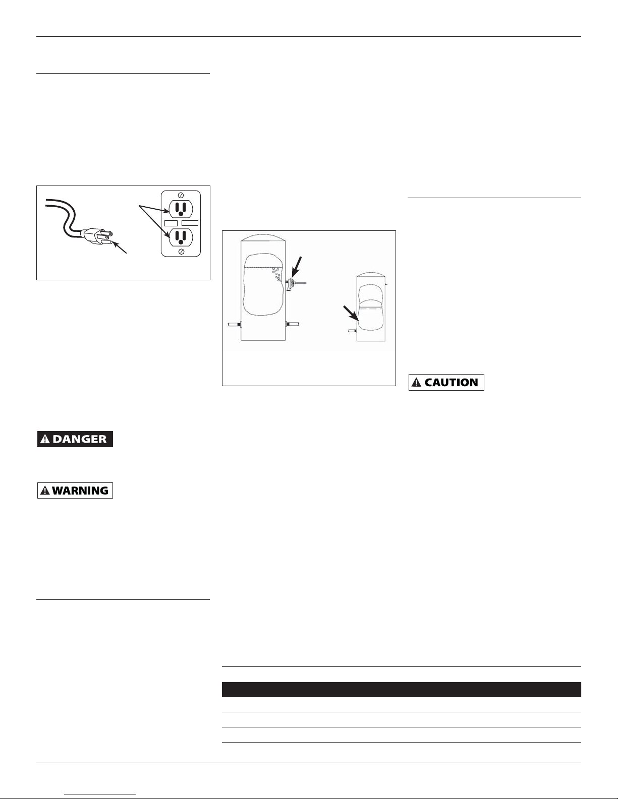
13. For maximum safety, the unit should
be connected to a grounded circuit
equipped with a ground fault
interrupter device.
14. Before installing the pump, have the
electrical outlet checked by a licensed
or certified electrician to make sure
the outlet is properly grounded.
15. Make sure the line voltage and
frequency of electrical current supply
agrees with the motor wiring.
16. Do not attempt repairs to the electric
motor. All repairs to the motor
must be completed at a licensed or
certified electrical motor repair shop.
Do not touch an
operating motor.
Modern motors are designed to operate
at high temperatures.
17. Avoid kinking electrical cord and
protect from sharp objects, hot
surfaces, oil and chemicals. Replace
or repair damaged or worn cords
immediately.
Disconnect power
and release all
pressure from the system before
attempting to install, service, relocate
or perform any maintenance. Lock the
power disconnect in the open position.
Tag the power disconnect to prevent
unexpected application of power.
18. Keep fingers and foreign objects
away from ventilation and other
openings. Do not insert any objects
into the motor.
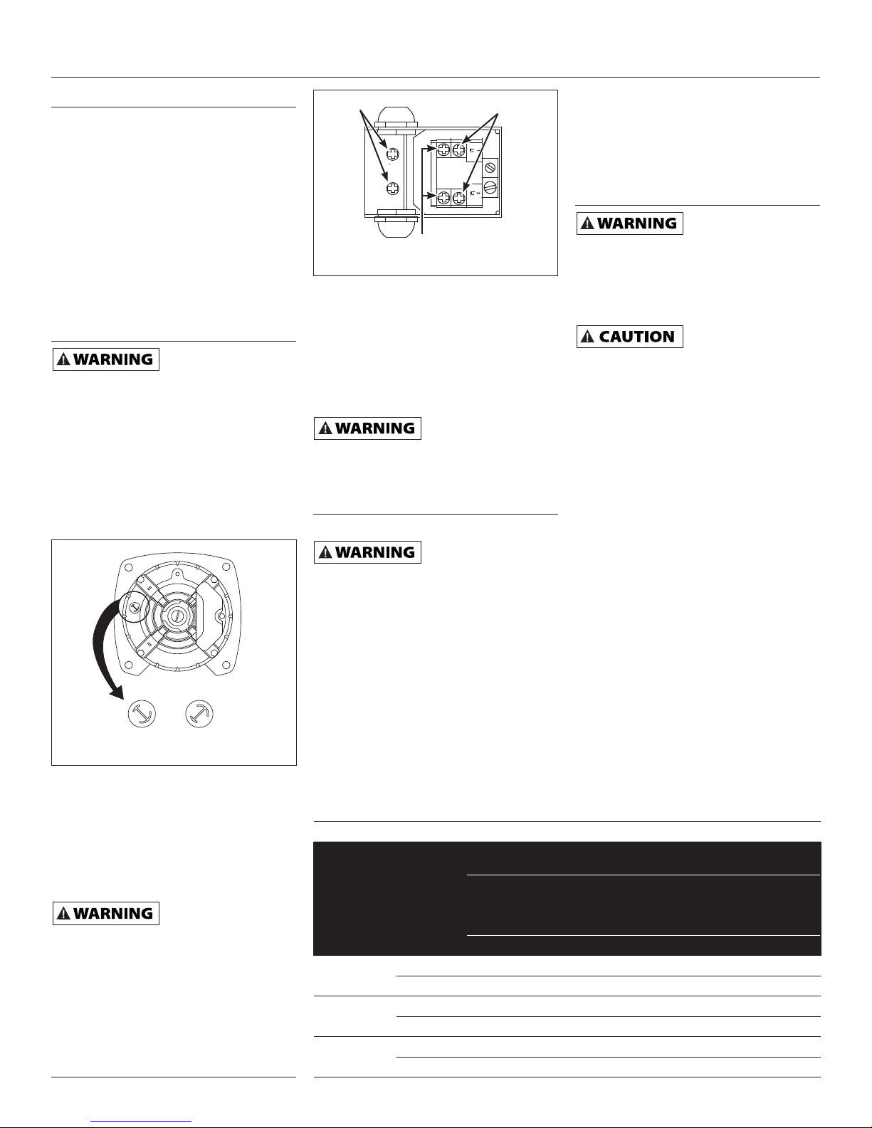
Risk of electric shock!
Never connect the
green (or green and yellow wire) to a
live terminal!
© 2010 WAYNE Water Pumps For parts, product & service information
visit www.waynepumps.com
Operating Instructions and Parts Manual Shallow well model systems
Jet Pump Water System
Please read and save these instructions. Read carefully before attempting to
assemble, install, operate or maintain the product described. Protect yourself
and others by observing all safety information. Failure to comply with
instructions could result in personal injury and/or property damage! Retain
instructions for future reference.

2
19. To reduce the risk of electrical
shock, the pump should be plugged
directly into a properly installed
and grounded 3-prong grounding
type receptacle, as shown in
Figure 1. The green (or green and
yellow) conductor in the cord is the
grounding wire. The motor must be
securely and adequately grounded
for protection against shock.
20. Where a 2-prong is encountered,
replace the plug with a properly
grounded 3-prong receptacle in
accordance with the National Electrical
Code, local codes and ordinances.
To ensure a proper ground, the
grounding means must be tested by a
licensed or certified electrician.
21. Use only 3-wire extension cords that
have a 3-prong, grounding type plug,
and 3-pole receptacles that accept
the equipment plug.
22. Use wire of adequate size to
minimize voltage drop at the motor.
Do not handle
pump or pump motor
with wet hands, when standing on a wet
or damp surface or when standing in
water. Fatal electrical shock could occur.
Pump motor is
equipped with an
automatic resetting thermal protector
and may restart unexpectedly. Protector
tripping is an indication of motor
overloading because of operating pump
at low heads (low discharge restriction),
excessively high or low voltage,
inadequate wiring, incorrect motor
connections or defective motor or pump.
Pre-Installation
WATER SUPPLIES
The water supplies illustrated in Figure
13 are possible sources for water. These
water supplies can be divided into two
categories:
SURFACE WATER
Water from a lake, stream, pond and
cistern. This water is usually not fit
for human consumption, but may be
suitable for washing, irrigation or other
household uses.
GROUND WATER
Water found in the water bearing
stratum at various levels beneath the
General Safety
Information (Continued)
earth. Of all the fresh water found on
earth only 3 percent is found on the
surface and 97 percent is underground.
TANKS - CONVENTIONAL STORAGE
The function of the tank is to store a
quantity of water under pressure. When
full, the tank contains approximately
2/3 water and 1/3 compressed air. The
compressed air forces the water out
of the tank when a faucet is opened.
An air volume control automatically
replaces air lost or absorbed into the
water. The usable water, or drawdown
capacity, of the tank is approximately
1/6 of the tanks total volume when
operated on a “20-40” pressure setting
(Figure 2).
TANKS - PRECHARGED STORAGE
A precharged storage tank has a flexible
bladder or diaphragm that acts as a
barrier between the compressed air
and water. This barrier prevents the
air from being absorbed into the water
and allows the water to be acted on by
compressed air at initially higher than
atmospheric pressures (precharged).
More usable water is provided than with
a conventional type tank. Precharged
tanks are specified in terms of a
conventional tank. For example, a 20
gallon precharged tank will have the same
usable water or drawdown capacity as a
40 gallon conventional tank, but the tank
is smaller in size (Figure 2).
PRESSURE SWITCH
The pressure switch provides for
automatic operation. The pump starts
when pressure drops to a cut-in setting.
The pump stops when pressure reaches a
cut-out setting.
TEST RESET
Grounded Pin
Grounded
Outlet
Figure 1
PACKAGE SYSTEMS
There are four jet pump/tank assemblies
sold as packages (Chart 1).
WELLS
A new well should be pumped clear of
sand before installing the pump. Sand
will damage the pumping parts and seal.
The draw-down level of the well should
not exceed the maximum rated depth
for the pump. The capacity of the pump
will be reduced and a loss of prime may
occur.
Installation
LOCATION
Select a location as close to the water
supply as possible. Be sure to comply
with any state or local codes regarding
the placement of the pump. The
equipment must be protected from the
elements. A basement or heated pump
house is a good location. Make sure
the pump has proper ventilation. The
temperature surrounding the pump is
not to exceed 100° F (40°C) or nuisance
tripping of the motor overload may
occur.
PIPING
Piping may be copper, steel, rigid PVC
plastic or flexible polyethylene plastic.
Flexible pipe is not
recommended on
suction pipe (inlet pipe).
The pipe must be clean and free of rust
or scale. Use a pipe joint compound
on the male threads of the metal pipe.
Teflon® tape should be used with plastic
threads. All connections must be air
tight to insure normal operation.
Slope all inlet piping upwards towards
the pump to prevent trapping air.
Unions or hose couplings can be
installed near pump to facilitate removal
for servicing or storage. A rubber hose
installed between the water system and
the house piping will reduce the noise
transmitted to the house.
PIPE SIZES
Long horizontal pipe runs and an
abundance of fittings and couplers
decrease water pressure due to friction
loss. See Chart 2 to determine the proper
pipe size.
www.waynepumps.com
Operating Instructions and Parts Manual Shallow Well Model Systems
Figure 2 - Conventional & Precharged
Storage Tanks
Precharged
Tank
Conventional
Tank
Bladder
Air Volume Control
CHART 1 - JET PUMP/ TANK ASSEMBLIES
Type Air Volume Congrol Required
Well X Precharged No
PCA Precharged No
12P & 30P Conventional Yes
FX Horizontal Precharged No

SHALLOW WELL PUMP WITH
CONVENTIONAL STORAGE TANK
(FIGURES 4 & 5)
1. Install air volume control on tank.
2. Connect the copper tube from the air
volume control to the uppermost 1/8”
NPT opening on the side of pump. Be
sure the connections are tight. Leaking
can cause the pump not to prime.
3. Install a valve and an isolator hose
between the tank and the house plumbing
to aid in pump removal for servicing and
for reducing the noise transmitted to the
house thrugh the piping.
4. Provide a hose bib (faucet) at the
lowest point in the system to drain
the system for service or storage.
SHALLOW WELL PUMP WITH
PRECHARGED STORAGE TANK
(FIGURE 6)
3
3. Add pipe until the foot valve is 5 feet
below the lowest anticipated water level.
The foot valve
should be at least 18”
from the bottom of the well or sand or
sediment could be drawn into the system.
4. After proper depth is reached, install
a well seal or pitless adapter to
support pipe and prevent surface
water and other contaminants from
entering well.
5. Slope the horizontal pipe upward
toward the pump to eliminate
trapping air. Sloping the pipe will
also aid in priming the pump.
DRIVEN WELL (FIGURE 13)
1. Drive the point several feet below the
water table.
NOTE: A packer type foot valve can
be installed in the well (Figure 3,
Illustration B). This type of foot valve
allows the well to be filled with water
when priming and makes the inlet pipe
much easier to test for leaks. Follow
the manufacturer’s instructions when
installing the packer type foot valve.
As an alternative, an in-line check valve
can be used with a driven well (Figure
3, Illustration C). The pipe between
the check valve and the water level will
always be under a vacuum.
Leaking joints or couplings will allow
air to leak into the pipe and cause
abnormal pump operation. Make sure
to use pipe joint compound on all male
pipe threads.
DUG WELL, CISTERN, LAKE AND
SPRING INSTALLATION (FIGURE 13)
1. Install a foot valve on inlet pipe and
lower into water.
The foot valve should
be at least 18” from
the bottom of the well or sand or
sediment could be drawn into the system.
NOTE: When a lake is used as a water
supply, make sure the inlet pipe is deep
enough to be submerged at all times.
Slope the horizontal piping upward
toward the pump to prevent trapping air.
The pipe must be removed during winter
months or protected against freezing.
Protect the pipe from damage from
swimmers and boats.
Install a screen
around the inlet pipe
to prevent the entrapment of swimmers.
www.waynepumps.com
Operating Instructions and Parts Manual Shallow Well Model Systems
Installation (Continued)
To Pump
Well
Seal
Foot
Valve
Well
Casing
To
Pump
To
Pump
Drive
Point
Drive
Point
Incline
Check
Valve
Packer
Type Foot
Valve
Illustration A
Illustration C
Illustration B
Figure 3
CHART 2 - PIPE SIZING
Pump Model
Pump
Opening
Horizontal Distance
(Feet)
0-25 26-100 100-300
Shallow Well Inlet 1-1/4 in. 1-1/2 in. 2 in.
Outlet 3/4 in. 1 1-1/4 in.
Figure 5 - Vertical Tank
Outlet
Air Volume
Control Tubing
Hose
Coupling
Air Volume Control
Figure 6 - Precharged Storage Tank
Motor Outlet Priming
Plug
Nozzle
Clean
Out
Drain
Fitting
28-30 psi
3/4 HP & 1 HP
SHALLOW WELL INSTALLATION
A shallow well pump can be used when
the pump is located within 25 feet
vertically of the water level. Shallow well
pumps have only one pipe between the
pump and the water supply (Figure 3).
DRILLED WELL (FIGURE 13)
1. Install a foot valve on the first section
of pipe (Figure 3, Illustration A).
2. Lower the pipe into the well.
Figure 4 - Horizontal Tank
Air Volume
Control
Tubing
To Suction
Air
Volume
Control
Pressure
Switch
Prime
Plug

4
Operating Instructions and Parts Manual Shallow Well Model Systems
1. Shut off the power to the pump.
2. Open the faucet nearest the tank and
allow all water to drain from the tank.
3. Measure the tank precharge at the
valve stem using a tire pressure gauge.
4. If necessary, precharge with an air
pump to 28 - 30 psi on 1/2, 3/4 and 1
HP pumps.
5. Slope the horizontal pipes upward
toward the pump to prevent trapping
air. If the horizontal distance
exceeds 25 feet, see Chart 2 for the
recommended pipe size.
Electrical
Risk of electrical
shock. This pump is
designed for indoor installation only.
The voltage of power supply must match
the voltage of the pump. All above
ground well pumps except SWS50BOOST
have dual voltage motors preset at the
factory to 115 volts. The motors can be
converted to 230 volts by turning the
voltage selector to the desired voltage
(See Figure 7). Use a needle nose pliers
to pull the selector out approximately
1/4”, rotate and then reinsert in correct
position.
Select the proper size wire and
fuse (Chart 3). Time delay fuses are
recommended over standard fuses for
motor circuit protection. All pump
motors have built-in automatic overload
protection that will prevent damage to
the motor due to overheating.
Do not connect to
electric power supply
until unit is permanently grounded.
Connect ground wire to approved
ground then connect terminal provided.
A metal underground water pipe or well
casing at least 10 feet long makes the
best ground electrode. If plastic pipe or
insulated fittings are used, run a wire
directly to the metal well casing or use
a ground electrode furnished by the
power company.
There is only one proper ground
terminal on the unit. The terminal(s) is
located under the pressure switch cover,
is painted green and is identified as
GRD. The ground connection must be
made at this terminal (Figure 8). The
ground conductor must not be smaller
than the circuit conductors supplying the
motor.
Disconnect power
and release all
pressure from the system before
attempting to install, service, relocate or
perform any maintenance.
Operation
PRIMING THE SHALLOW WELL PUMP
To prevent damage
to the pump, do not
start motor until pump has been filled
with water.
1. Remove prime plug (Figure 4 or 5).
2. Fill pump and piping completely full
of water.
3. Replace the prime plug.
4. Open a faucet to vent the system.
5. Start the motor. Water will pump in
a few minutes. If pump fails to prime
in 5 minutes, stop motor and refill
pump with water. Priming time is
proportional to the amount of air in
inlet pipe.
6. Let the system operate for several
minutes to flush all pipes.
7. Close faucet and allow pump to build
pressure in tank. When the pressure
reaches the cut-out setting, the
motor will stop.
The system is now in operation and will
automatically cycle on demand.
Maintenance
Disconnect power
and release all
pressure from the system before
attempting to install, service, relocate
or perform any maintenance. Lock the
power disconnect in the open position.
Tag the power disconnect to prevent
unexpected application of power.
Protect the pump
from freezing during
winter conditions.
DRAINING THE PUMP
Drain openings are provided on all
models. To drain the pump:
1. Remove drain plug and prime plug to
vent the system.
2. Drain all piping to a point below the
freeze line.
DRAINING THE TANK
Conventional tanks can be drained by
opening an outlet at the lowest point
in the system. Remove plug or the air
volume control to vent the tank.
Precharged tanks force virtually all
the water from the tank when system
pressure is released. No draining is
necessary.
RESTARTING PUMP
If the pump has been serviced, drained
or has not been used for some time,
be sure there is water in the pump
housing (volute) and the piping to the
well. There must be water in the pump
housing (volute) at all times when
the pump is running to avoid internal
damage of seal members (Priming the
Shallow Well).
www.waynepumps.com
115 V
230 V
115 V
230 V
Figure 7 - Voltage Selector
L2
3
L1
1
Figure 8 - Electrical Connections
Line
Motor
Ground
Screw
CHART 3 - RECOMMENDED FUSE & WIRING DATA - 60 HZ MOTORS
HP VOLT
Distance in Feet
From Meter to Motor
0 51 101 201
to to to to
50 100 200 300
Wire Size
1/2 115 15 14 14 10
230 10 14 14 14
3/4 115 15 14 14 8
230 10 14 14 14
1115 20 12 12 8
230 10 14 14 14
Installation (Continued)

cardboard washer to protect pol-
ished surface when pushing against
ceramic seat with any object. Be sure
to remove cardboard washer.
2. Carefully slip seal plate over shaft. Do
not disturb seal position in seal plate.
The seal plate must be orientated
during assembly so the two screw holes
are on a horizontal line across the
motor shaft and the (4) locating pins on
the back of the seal plate line up with
the tabs on the motor housing (Figure
11). This placement should be done to
ensure proper draining and priming.
3. Place rotating shaft seal member in
position on impeller and press into
place. Take care not to press against
polished seal surface.
4. Position impeller on shaft and
tighten securely (Figure 12).
5. Secure diffuser to seal plate using
the two cap screws. Be sure the
screws are orientated on a horizontal
line as described in Step 2.
6. Carefully position pump housing
(volute) gasket over the diffuser
onto the seal plate. In all shallow
well applications care must be taken
that the o-ring is clean and properly
positioned on the venturi. Cleaning
and positioning makes a good seal
inside the diffuser when assembled.
7. Assemble the pump housing (volute)
to the motor using the four cap
screws. Be sure the pump housing
(volute) gasket is positioned correctly
and tighten the screws securely.
NOTE: Shaft must rotate freely and
motor end cap should be secured before
operation.
1. Open a faucet nearest the tank and
allow all water to drain from the tank.
2. Remove the four cap screws holding
the pump housing (volute) to the
motor (Figure 9).
3. Separate the pump housing (volute)
from the motor to expose the diffuser
and the seal plate.
4. Remove the two cap screws and
diffuser from the seal plate to expose
the impeller.
5. Remove the small end cap on the end
of the motor opposite the impeller.
6. With a large screwdriver or adjustable
wrench, keep the shaft from rotating
and remove the impeller by hand
(standard right hand thread). Be
sure to hold onto the seal plate when
removing the impeller from the shaft.
7. Remove the seal plate.
8. Pry the rotating shaft seal member
from the impeller (Figure 10).
9. Push or pry the ceramic seat free
from the seal plate (Figure 10).
10. Remove loose particles from impeller
hub and seal plate.
INSTALLING NEW SHAFT SEAL
Before handling shaft
seal parts wipe hands
clean. Dirt or grease can damage the seal.
1. Wet the inside of the seal cavity
on seal plate and the rubber cup
enclosing the new ceramic seat with
cooking oil. Be careful not to scratch
the ceramic surface of the seal seat
and push seat enclosed in rubber
into seal cavity on seal plate. Use a
Figure 11 - Seal Plate Replacement
Screw
Holes
Motor
Shaft
Figure 10 - Removing Shaft Seal and
Ceramic Seat
Seal
Plate
Rubber
Seat Ring
Ceramic
Seat
Rotating
Shaft Seal
Member Impeller
5
Operating Instructions and Parts Manual Shallow Well Model Systems
www.waynepumps.com
Figure 12 - Motor Shaft
Seal
Facing
Must
Be Clean For
Proper Seal
Motor
Seal
Plate
Impeller
Seal
Seat
Seal Plate
WATERLOGGED TANKS:
CONVENTIONAL
When a tank system has an inadequate
ratio of air and water, the pump will
start and stop often and eradically.
1. Disconnect the power to the pump.
2. Open the lowest faucet in the system
to release all pressurized water in the
system.
3. Prime the pump (Priming the Shallow
Well).
4. Reconnect the power to the pump.
NOTE: As the pump refills the tank with
water, the air volume control supplies
the tank with the correct air to water
ratio for the system to operate. If the
air volume control is good, the pump
will shut off at the desired cut-off and
will be adjusted correctly.
WATERLOGGED TANKS: PRECHARGED
If a precharged tank becomes waterlogged,
the bladder is normally leaking or broken.
1. Test the tank by depressing the air
valve. The air valve will expel water
if the bladder is broken.
2. Replace the tank.
NOTE: Once a bladder is leaking or
broken, the bladder cannot be repaired.
The tank must be replaced.
LUBRICATION
The bearings used in the pumps are
lifetime lubricated at the factory and
require no additional lubrication.
PRECHARGED TANK
Some air is lost through the bladder in
any tank. To prevent tank failure, check
the tank precharge on a yearly basis.
1. Open a faucet nearest the tank and
allow all water to drain from the tank.
2. Measure the tank precharge at the
valve stem using a tire gauge.
3. If necessary, adjust the precharge
with an air pump 28 - 30 psi on 1/2,
3/4 and 1 HP pumps.
REMOVING OLD SHAFT SEAL
Turn disconnect
switch to “off” position.
Maintenance (Continued)
Figure 9 - Shaft Seal
Cap Screws Seal Plate
Diffuser
Cap Screws
Pump
Housing
(Volute)
Motor
Impeller
Venturi

6
Operating Instructions and Parts Manual Shallow Well Model Systems
www.waynepumps.com
Notes

7
Operating Instructions and Parts Manual Shallow Well Model Systems
Notes
www.waynepumps.com

8
Operating Instructions and Parts Manual Shallow Well Model Systems
www.waynepumps.com
Notes

9
Operating Instructions and Parts Manual Shallow Well Model Systems
www.waynepumps.com
Troubleshooting Chart
ELECTRICAL PRECAUTIONS - Before servicing a pump, always shut off the main power breaker and then unplug
the pump. Make sure you are not standing in water and are wearing insulated protective sole shoes. Under flooded
conditions, contact your local electric company or qualified licensed electrician for disconnecting electrical service prior to pump removal.
Symptom Possible Cause(s) Corrective Action
Pump will not run 1. Power off
2. Blown fuse or tripped breaker
3. Faulty pressure switch
4. Motor overload tripped
1. Turn power on or call power company
2. Replace fuse or reset circuit breaker
3. Replace switch
4. Let cool. Overload will automatically reset
Motor hums but will not run 1. Voltage does not match selector switch
2. Wiring too small
3. Damage or misalignment causing rotating
parts to bind
1. Check voltage
2. Rewire. See Chart 4*
3. Replace or take to service shop for repair
Overload trips 1. Incorrect line voltage
2. Damage or misalignment causing rotating
parts to bind
3. High surrounding temperature
4. Rapid cycling
1. Rewire. See Chart 4*
2. Take to motor repair shop or locate and repair
mechanical binding
3. Provide a shaded, well-ventilated area for pump
4. Pump starts and stops too often section
Pump runs but delivers little or
no water
1. Water level below pump intake
2. Control valve open too far (deep well)
3. Discharge not vented while priming
4. Leaking in piping on well side of pump
5. Well screen or inlet strainer clogged
6. Clogged nozzle (deep well)
7. Air volume control diaphragm ruptured
8. Foot valve may be clogged or stuck closed
9. Pump not fully primed
10. Control valve completely closed (deep well)
11. Water level below maximum lift specification
12. Undersized piping
13. Gaseous well
14. Distorted venturi
15. Incorrect jet for application
16. Undersized pump
17. Pump cavitates, sounds like pumping gravel
1. Lower suction pipe further into well
2. Adjust control valve or repeat priming procedure.
3. Open faucet, repeat priming procedure
4. Repair piping as needed
5. Clean or replace as necessary
6. Pull jet and clear obstruction
7. Repair or replace air volume control
8. Clean or replace as needed
9. Continue priming, pausing every 5 minutes to cool
pump body. Refill pump as needed
10. Adjust control valve per deep well priming
procedure
11. Select applicable pump and/or jet assembly
12. Replace as needed
13. Install baffle on pump intake to prevent gas from
entering system
14. Inspect and replace
15. Purchase a jet matched to your system when
replacing another brand pump
16. Increase horsepower of pump
17. Increase suction plumbing diameter or decrease
pipe friction
Pump starts and stops too often 1. Water logged tank (conventional tank)
2. Air volume control tubing kinked or clogged
3. Air volume control tubing connected to
wrong opening on pump
4. Incorrect tank pre-charged (pre-charged
tank)
5. Ruptured diaphragm/bladder (pre-charged
tank)
6. Leak in house piping
7. Foot valve or check valve stuck open
8. Motor overload tripping
9. Improperly adjusted pressure switch
1. Replace tank or air volume control
2. Clean or replace as needed
3. Move to correct pump opening
4. Add or release air as needed
5. Replace tank
6. Locate and repair leak
7. Remove and replace
8. See overload trips section
9. Readjust or replace switch

10
For Replacement Parts, call 1-888-636-6628
Please provide following information: Address parts correspondence to:
- Model number WAYNE Pumps
- Serial number (if any) 101 Production Drive
- Part description and number as shown in parts list Harrison, OH 45030 U.S.A.
Ref.
No. Description
Part Numbers
Qty.SWS50-1/2 HP SWS75-3/4 HP SWS100-1 HP
1 Motor 32059-001 34142-001 34142-001 1
2 Screw 16636-002 16636-002 16636-002 4
3 Seal plate 4372-001 4372-001 4372-001 1
4 • Square ring rubber gasket 17150-001 17150-001 17150-001 1
5 • Shaft seal assembly 56393 56393 56393 1
6 Impeller 23285-021 23285-022 23285-022 1
7 Diffuser 17148-021 17148-021 17148-021 1
8 Screw 67007-001 67007-001 67007-001 2
9 • O-ring 15557 15557 15557 1
10 Venturi 17151-002 17151-003 17151-004 1
11 Nozzle 15672 15672 15672 1
12 Pipe plug 3/4” 15921 15921 15921 1
13 Volute 56869-001 56869-001 56869-001 1
14 Pipe plug 1/4” NPT 16314-002 16314-002 16314-002 1
15 Pipe plug 1/8” NPT 15766-002 15766-002 15766-002 1
16 Base 23029-021 23029-021 23029-021 1
17 Pressure switch 30010-021 30010-021 30010-021 1
• Repair kit (Includes #4, 5 and 9) 56874-001 56874-001 56874-001 1
17
16
15
14
13
12
11
10
98
7
6
5
4
3
2
1
Operating Instructions and Parts Manual Shallow Well Model Systems
www.waynepumps.com

11
Operating Instructions and Parts Manual Shallow Well Model Systems
(A) SPRING:
A spring that emerges
from the ground.
Occurs when water in
permeable materials is
trapped between
impermeable
material as rock or clay.
(B) LAKE, STREAM or POND:
Surface water, unless treated,
is usually not safe for human
consumption. It may be used
for purposes such as washing
or irrigation.
(C) DUG WELL:
A hole is excavated
several feet in diameter
to a fairly shallow
depth. It is then lined
with brick, stone or
concrete to prevent
cave-in.
(D) DRIVEN WELL:
Pipe with a pointed
screen is driven into
the ground below
the water table.
The depth is usually
less than 50 feet.
Available
diameters are
1" through 2".
(E) DRILLED WELL:
A hole bored into the
earth with machinery and
lined with pipe. Depths
range from a few feet
to over 1000 feet.
Common well diameters
are 2", 3", 4" and 6" for
domestic water wells.
(F) CISTERN:
An underground tank
built to collect rain
water from rooftops.
The water is not fit
for human consumption.
(A) SPRING
(B) LAKE,
STREAM, POND
(C) DUG WELL
(D) DRIVEN WELL (E) DRILLED WELL (F) CISTERN
SHALE
TOP SOIL
CLAY
PERMEABLE
MATERIAL
WATER
BEARING
SAND
WATER TABLE
Figure 13 - Well types
www.waynepumps.com

12
Operating Instructions and Parts Manual Shallow Well Model Systems
www.waynepumps.com
Limited Warranty
For three years from the date of purchase, WAYNE Water Systems (“WAYNE”) will repair or replace, at its option, for the original
purchaser any part or parts of its Pond Kit, Sump Pumps or Water Pumps (“Product”) found upon examination by WAYNE to
be defective in materials or workmanship. Please call WAYNE (800-237-0987) for instructions or see your dealer. Be prepared to
provide the model and serial number when exercising this warranty. All transportation charges on Products or parts submitted
for repair or replacement must be paid by purchaser.
This Limited Warranty does not cover Products which have been damaged as a result of accident, abuse, misuse, neglect,
improper installation, improper maintenance, or failure to operate in accordance with WAYNE’s written instructions.
THERE IS NO OTHER EXPRESS WARRANTY. IMPLIED WARRANTIES, INCLUDING THOSE OF MERCHANTABILITY AND
FITNESS FOR A PARTICULAR PURPOSE, ARE LIMITED TO THREE YEARS FROM THE DATE OF PURCHASE. THIS IS THE
EXCLUSIVE REMEDY AND ANY LIABILITY FOR ANY AND ALL INDIRECT OR CONSEQUENTIAL DAMAGES OR EXPENSES
WHATSOEVER IS EXCLUDED.
Some states do not allow limitations on how long an implied warranty lasts, or do not allow the exclusions or limitations of
incidental or consequential damages, so the above limitations might not apply to you. This limited warranty gives you specific
legal rights, and you may also have other legal rights which vary from state to state.
In no event, whether as a result of breach of contract warranty, tort (including negligence) or otherwise, shall WAYNE or its
suppliers be liable for any special, consequential, incidental or penal damages including, but not limited to loss of profit or
revenues, loss of use of the products or any associated equipment, damage to associated equipment, cost of capital, cost of
substitute products, facilities, services or replacement power, downtime costs, or claims of buyer’s customers for such damages.
You MUST retain your purchase receipt along with this form. In the event you need to exercise a warranty claim, you MUST
send a copy of the purchase receipt along with the material or correspondence. Please call WAYNE (800-237-0987) for return
authorization and instructions.
DO NOT MAIL THIS FORM TO WAYNE. Use this form only to maintain your records.
MODEL NO. _____________________ SERIAL NO. ________________________ INSTALLATION DATE _____________________
ATTACH YOUR RECEIPT HERE

MÉMENTO: Gardez votre preuve datée d’achat à fin de la garantie! Joignez-la à ce manuel ou classez-la dans un dossier pour plus de sécurité.
S’il vous plaît lire et conserver ces instructions. Lire attentivement avant de monter, installer, utiliser ou de procéder à l’entretien
du produit décrit. Se protéger ainsi que les autres en observant toutes les instructions de sécurité, sinon, il y a risque de blessure
et/ou dégâts matériels! Conserver ces instructions comme référence.
340107-001 9/10
© 2010 WAYNE Water Pumps
Instructions d’Utilisation et Manuel de Pièces Systèms de modèles pour puits de surface
Systèmes D’Eau De
Pompe À Jet
Description
Les pompes à jet pour puits de surface
sont des pompes à eau à une étage
à usage domestique conçues pour
le pompage d’eau potable là où la
source d’eau est située moins de 7,62
m verticalement de la pompe. Un
manostat est standard. La pompe pour
puits de surface peut être montée sur un
réservoir de pression chargé d’avance,
traditionnel, ou autoportant.
Déballage
Lors du déballage de la pompe à jet,
l’inspecter soigneusement afin de
rechercher toute trace de dommage
susceptible de s’être produit en cours
de transport. Vérifier pour des pièces
dégagées, endommagées, ou manquantes.
Directives de Sécurité
Ce manuel contient de l’information très
importante de connaître et de savoir
qui est fournie pour la SÉCURITÉ et pour
ÉVITER LES PROBLÈMES D’ÉQUIPEMENT.
Rechercher les symboles suivants pour
cette information.
Danger indique une
situation hasardeuse
imminente qui RÉSULTERA en perte de vie ou
blessures graves.
Avertissement
indique une situation
hasardeuse potentielle qui PEUT résulter en
perte de vie ou blessures graves.
Attention indique
une situation
hasardeuse potentielle qui PEUT résulter en
blessures.
Avis indique de
l’information
importante pour éviter le dommage de
l’équipement.
Généralités sur la
Sécurité
1. Lire attentivement le manuel
d’instructions compris avec le produit.
Bien se familiariser avec les contrôles
et le fonctionnement correct de
l’équipement.
2. Connaissez l’application de la pompe,
ses limites et tous les risques.
Toujours installer
une soupape de
sûreté correspondante à la classification
de pression du système et au taux de débit
maximum.
Ne pas pomper les
liquides inflammables
ou explosifs tels que l’essence, l’huile à
chauffage, le kérosène, etc. Ne pas utiliser
dans un atmosphère explosif. Utiliser
la pompe seulement avec les liquides
compatibles avec les matériaux de fabrication
de la pompe. Manque de suivre cet
avertissement peut résulter en blessures
graves et/ou en dégâts matériels.
Mettre hors circuit
et dissiper toute
la pression du système avant d’essayer
de monter, de déplacer ou de procéder
au service ou à l’entretien. Verouiller le
sectionneur de puissance dans la position
ouverte. Étiquetter le sectionneur de
puissance afin d’éviter l’alimentation
inattendue.
Installer un écran
de protection autour
du tuyau d’admission pour empêcher
d’emprisonner les nageurs.
3. Purger tous les liquides du système
avant de procéder au service.
4. Fixer la ligne de décharge avant le
démarrage de la pompe. Une ligne
qui n’est pas bien fixée pourrait
fouetter et causer des blessures
personnelles et/ou le dégât matériel.
5. Inspecter les tuyaux pour la faiblaisse
ou l’usure avant chaque usage.
S’assurer que tous raccordements
soient sûrs.
6. Inspecter la pompe et les
pièces détachées du système
périodiquement. Procéder à
l’entretien ordinaire au besoin (Voir
la section Entretien).
7. Sécurité Personnelle:
a. Toujours porter des lunettes de
sécurité pendant l’utilisation d’une
pompe.
b. Garder l’endroit de travail
propre, pas encombré et bien
éclairé. Ranger tous les outils et
l’équipement dont on ne se sert pas.
c. Garder les visiteurs à distance
respectueuse de l’endroit de travail.
d. Protéger l’atelier des enfants
en utilisant des cadenas et des
interrupteurs principals. Enlever les
clés de démarrage.
8. Ne pas pomper de produits chimiques
ni de liquides corrosives. Le pompage
de ces liquides peut raccourcir la
durée des joints et des pièces mobiles
de la pompe et niera la garantie.
9. Couvrir le puits pendant l’installation
de la pompe afin d’empêcher le
débris de tomber dans le puits
qui pourrait contaminer l’eau et
endommager les pièces mécaniques
internes de pompage.
10. Toujours faire l’essai de l’eau du
puits pour la pureté avant l’usage.
Contacter votre Ministère de Santé
pour la méthode de mise à l’essai.
11. Le système complet de pompe et de
tuyaux DOIT être protégé contre les
températures inférieures à zéro. Les
témpératures congélantes peuvent
causer le dommage sérieux et nieront
la garantie.
12. Ne pas faire fonctionner la pompe au
sec, ceci l’endommagera.
Risque de secousse
électrique. Cette
pompe est conçue pour l’installation à
l’intérieure seulement.
Toute nstallation
de fils doit être
effectuée par un électricien certifié ou
diplômé.
13. Pour la sécurité maximum, le modèle
devrait être branché à un circuit
de terre équipé d’un appareil qui
protège contre le dérangement dû à
une mise accidentelle à la terre.
14. Faire instpecter la prise de courant par
un électricien diplômé ou certifié afin
d’assurer que la prise soit mise à la terre
correctement avant d’installer la pompe.
15. S’assurer que la tension de ligne et
que la fréquence de la source de
courant électrique soient compatibles
avec l’installation de fils du moteur.
16. Ne pas essayer de réparer le moteur
électrique. Toutes réparations
du moteur électrique doivent
être complétées à un atelier de
réparations de moteur certifié.

14 Fr
Instructions d’Utilisation et Manuel de Pièces Systèms de modèles pour puits de surface
Figure 2 - Réservoirs Traditionnels et
Chargés D’Avance
Réservoir Chargé
D’Avance
Réservoir
Traditionnel
Vessie
Contrôle de Volume
d’Air
Généralités sur la
Sécurité (Suite)
Ne jamais toucher
un moteur en marche.
Les moteurs modernes sont conçus pour le
fonctionnement aux températures élevées.
17. Éviter le tortillement du cordon
d’alimentation et protéger le cordon
d’alimentation contre les objets
pointus, les surfaces chaudes, l’huile
et les produits chimiques. Remplacer
ou réparer les cordons endommagés
ou usés immédiatement.
Débrancher la
source d’alimentation
et dissiper toute la pression du système
avant d’essayer d’installer, de déplacer ou de
procéder au service ou à l’entretien. Verouiller
le sectionner d’alimentation dans la position
ouverte. Étiquetter le sectionner d’alimentation
afin d’éviter l’alimentation inattendue.
18. Garder les doigts et les objets à
l’écart des ouvertures telles que celles
de ventilation. Ne jamais introduire
des objects dans le moteur
Risque de secousse
électrique! Ne jamais
brancher le fil vert (ou vert et jaune) à une
borne sous tension!
19. Pour réduire le risque de secousse
électrique, la pompe devrait être
branchée directement dans une prise
de courant à 3 broches mise à la terre et
installée correctement telle qu’indiquée
sur la Figure 1. Le fil conducteur vert
(ou vert et jaune) dans le cordon est
le fil de terre. Le moteur doit être mis
à la terre avec sûreté afin de protéger
contre les secousses électriques.
20. S’il y a une prise à 2 broches,
remplacer la prise avec une prise de
courant à 3 broches mise à la terre
correctement conformément aux
Code Électrique National (National
Electrical Code) et aux codes et
règlements locaux. Assurer une mise
à la terre correcte requiert l’inspection
par un électricien certifié ou diplômé.
21. Utiliser seulement les cordons
prolongateurs à 3 fils ayant une fiche
mise à la terre à 3 broches et prises de
courant tripolaires qui acceptent la
fiche de l’équipement.
22. Utiliser un fil de taille suffisante afin
de réduire la perte de tension au
moteur.
Ne pas manipuler
la pompe ni le moteur
de pompe avec les mains trempes, si debout
sur une surface trempe ou humide ou
debout dans l’eau. Ceci peut résulter en
secousse électrique mortelle.
Le moteur de la
pompe est équipé d’un
protecteur thermique à réenclenchement
automatique et peut se mettre en marche
sans avis. Le déclenchement du protecteur
indique le surcharge du moteur causé par
l’opération de la pompe avec une restriction
de décharge basse, tension très élevée
ou basse, installation de fils incorrecte,
branchements de moteur incorrects ou
moteur/pompe défectueux.
Pré-Installation
SOURCES D’EAU
Les sources d’eau possibles sont
indiquées sur la Figure 13. Les deux
catégories de sources d’eau sont:
L’EAU DE SURFACE
L’eau de lac, ruisseau, étang et réservoir.
Cette eau est généralement impropre à
la consommation, mais peut être utilisée
pour le lavage, l’irrigation ou autres
usages domestiques.
EAU SOUTERRAINE
L’eau existe dans la strate souterraine à
plusieurs niveaux. De toutes les sources
d’eau fraiche sur la terre, seulement 3
pourcent est à la surface, et 97 pourcent
est souterraine.
RÉSERVOIRS - ENTREPOSAGE
TRADITIONNEL
La fonction du réservoir est de
garder une quantité d’eau sous
pression. Le réservoir plein contient
approximativement 2/3 eau et 1/3 air
comprimé. L’air comprimé force l’eau
hors du réservoir lorsqu’un robinet
est ouvert. Un contrôle de volume
d’air remplace automatiquement
l’air perdue ou absorbée. L’eau
utilisable, ou la capacité du réservoir est
approximativement 1/6 du volume total
du réservoir si réglé à un réglage de
pression de “138-276 kPa” (Figure 2).
RÉSERVOIRS CHARGÉS D’AVANCE
Un réservoir chargé d’avance a une
vessie ou diaphragme qui fonctionne
comme une barrière entre l’air
comprimé et l’eau. Cette barrière
empêche l’absorption d’air dans l’eau
et permet l’action par l’air comprimé
aux pressions de début plus élevées
que la pression atmospérique (chargé
d’avance). Plus d’eau utilisable est
fournie par rapport aux réservoirs
traditionnels. Les réservoirs chargés
d’avance sont spécifiés par rapport aux
réservoirs traditionnels. Un réservoir
chargé d’avance de 75,7 L aura la même
capacité d’eau utilisable qu’un réservoir
traditionnel de 151,4 L, mais le réservoir
est plus petit (Figure 2).
MANOSTAT
Le manostat est fournit pour l’opération
automatique. La pompe se met en
marche quand la pression tombe à
un réglage de mis en marche réglé
d’avance. La pompe s’arrête quand la
pression atteint le réglage d’arrêt réglé
d’avance.
SYSTÈMES EN PAQUETS
Il y a quatre montages de pompe à
jet/réservoir disponibles en paquets
(Tableau 1).
PUITS
Un puits nouveau devrait être vidé de
sable avant l’installation de la pompe.
Le sable pourrait endommager les pièces
et le joint de la pompe. Le niveau
d’aspiration du puits ne devrait pas
dépasser la classification de profondeur
maximum de la pompe. Ceci pourrait
réduire la capacité de la pompe et la
pompe pourrait perdre son amorçage.
TEST RESET
Broche
de terre Prise de courant
mise à la terre
Figure 1
TABLEAU 1 - MONTAGES DE POMPE À JET/RÉSERVOIR
Type Air Volume Congrol Required
Puits X Chargé d’avance Non
PCA Chargé d’avance Non
12P & 30P Horizontal Traditionnel Oui
FX Horizontal Chargé d’avance Non

15 Fr
Instructions d’Utilisation et Manuel de Pièces Systèms de modèles pour puits de surface
À la pompe
Joint de
puits
Clapet
de pied
Coffrage
de puits
À la
pompe
À la
pompe
Point
d’Enfoncement
Point
d’Enfoncement
Clapet en
Canalisation
Clapet de Pied
d’Étanchéité
Illustration A
Illustration C
Illustration B
Figure 3
TABLEAU 2 - TAILLES DE TUYAUX
Modèle
Pump
Opening
Distance Horizontale (Metres)
0-7,62 7,93-30,5 7,93-91,4
Puits Profund Arrivée 1-1/4 po 1-1/2 po 2 po
Sortie 3/4 po 1 po 1-1/4 po
Installation
SITUATION
Choisissez un endroit aussi près de
la source d’eau que possible. Placer
la pompe conformément aux codes
nationaux ou locaux. L’équipement
doit être protégé contre les éléments.
Un bon endroit peut être un sous-sol
ou une station de pompage chauffée.
S’assurer que la ventilation à la pompe
soit suffisante. La température autour
de la pompe ne doit pas dépasser 40°C
car ceci peut causer le déclenchement du
protecteur de surchage de moteur.
TUYAUTERIE
Utiliser la tuyauterie en cuivre, en acier,
en plastique CPV rigide ou en plastique
flexible polyéthylène.
L’utilisation des
tuyaux flexibles n’est
pas recommandée sur le tuyau d’aspiration
(tuyau d’admission).
Le tuyau doit être propre et libre
de rouille ou d’écailles. Utiliser un
composé de joint sur les filets mâles
du tuyau métallique. Utiliser le ruban
Teflon® sur les filets en plastique.
Tous les raccordements doivent être
étanches à l’air afin d’assurer le bon
fonctionnement.
Incliner tous les tuyaux d’admission
en haut vers la pompe afin d’éviter la
prise d’air. L’utilisation des raccords
ou accouplements de tuyaux près de la
pompe peuvent faciliter le démontage
pour le service ou l’entreposage. Un
tuyau en caoutchouc installé entre le
système d’eau et la tuyauterie de maison
peut réduire le bruit dans la maison.
TAILLES DE TUYAUX
Les chemins de tuyaux longs et
horizontaux l’utilisation de trop de
raccords et d’accouplements peuvent
diminuer la pression d’eau à cause de
pertes par le frottement. Se référer au
Tableau 2 pour les tailles correctes de
tuyaux.
INSTALLATION DE PUITS DE SURFACE
Utiliser une pompe pour puits de surface
si la pompe est située à moins de 7,62
m verticalement du niveau d’eau. Les
pompes pour puits de surface ont un
seul tuyau entre la pompe et la source
d’eau (Figure 3).
PUITS FORÉ (FIGURE 13)
1. Installer un clapet de pied sur la
première section de tuyau (Figure 3,
Illustration A).
2. Baisser le tuyau dans le puits.
3. Ajouter des tuyaux jusqu’à ce que le
clapet soit 1,5 m sous le niveau d’eau
le plus bas possible.
Situer le clapet de
pied au moins 18 po
du fond du puits afin d’éviter l’aspiration de
sable ou de sédiment dans le système.
4. Une fois que la profondeur correcte
soit atteinte, installer un joint de
puits ou adaptateur pour soutenir le
tuyau et pour empêcher la pollution
du puits par l’eau de surface ou
autres polluants.
5. Incliner le tuyau horizontal en
haut vers la pompe pour empêcher
d’emprisonner l’air. L’inclinaison aide
aussi à l’amorçage de la pompe.
PUITS ENFONCÉ (FIGURE 13)
1. Enfoncer le point plusieurs mètres
sous le niveau hydrostatique.
REMARQUE: Un clapet de pied
d’étanchéité peut être installé dans le
puits (Figure 3, Illustration B). Ce type
de clapet de pied permet que le puits
se remplisse d’eau pendant l’amorçage
et facilite la recherche des fuites.
Respectez les instructions du fabricant
pendant l’installation du clapet de pied
d’étanchéité.
Alternativement, un clapet en
canalisation peut être utilisé avec un
puits creusé (Figure 3, Illustration C). Le
tuyau entre le clapet et le niveau d’eau
sera toujours à vide.
Des fuites dans les joints ou dans les
accouplements permetteront l’air de
s’échapper dans le tuyau et causera le
fonctionnement abnormal de la pompe.
S’assurer d’utiliser du composé pour
joints sur tous les filets mâles.
INSTALLATION POUR PUITS CREUSÉS,
CITERNES, LACS ET SOURCES (FIGURE 13)
1. Installer un clapet de pied sur le
tuyau d’admission et le submerger.
Situer le clapet de
pied au moins 18 po du
fond du puits afin d’éviter l’aspiration de
sable ou de sédiment dans le système.
REMARQUE: Si un lac est la source
d’eau, s’assurer que le tuyau d’admission
soit assez profond pour qu’il demeure
immergé.
Incliner le tuyau horizontal en haut vers
la pompe afin d’éviter d’emprisonner
l’air. Enlever le tuyau pendant l’hiver ou
le protéger contre le gel.
Protéger le tuyau contre le dommage
causé par les nageurs et les bateaux.

Choisissez la taille correcte de fusible
et de fil (Tableau 3). Les fusibles à
retardement sont recommandés pour
la protection des circuits de moteur.
Tous les moteurs de pompes ont un
protecteur de surcharge automatique
qui empêche le dommage au moteur
causé par le surchauffage.
Ne pas brancher à
une source
d’alimentation électrique jusqu’à ce que
le modèle soit mis à la terre correctement.
Connecter le fil de terre à une source de
terre approuvée et ensuite connecter la
borne fournie.
Un tuyau d’eau métallique souterrain
ou un coffret de puits au moins 3 m de
long sont en permanance l’idéals comme
électrode de terre. Si un tuyau en plastique
ou des raccords isolés sont utilisés, filer
un fil directement au coffrage de puits
métallique ou utiliser un électrode de terre
fournit par la compagnie d’électricité.
Il y a seulement une borne de mise à la terre
correcte sur le modèle. La borne(s) est située
sous le couvercle du manostat, est peinturée
verte et est identifiée par les lettres GRD.
La connexion de mise à la terre doit être
complétée à cette borne (Figure 8). Le fil de
terre doit être au moins la même taille que
les fils de circuits qui alimentent le moteur.
Débrancher de
l’alimentation
électrique et dissiper toute la pression du
système avant d’essayer d’installer, de
déplacer ou de procéder au service ou à
l’entretien.
1. Couper l’alimentation électrique à la
pompe.
2. Ouvrir le robinet près du réservoir
et permettre que l’eau s’écoule du
réservoir.
3. Mesurer la charge du réservoir avec
un manomètre pour pneus.
4. Charger d’avance, si nécessaire avec
une pompe à air à 193 - 207 kPa sur
les pompes de 1/2, 3/4 et 1 HP.
5. Incliner les tuyaux horizontaux en
haut vers la pompe afin d’empêcher
d’emprisonner l’air. Si la distance
horizontale dépasse 7,6 m, voir le
Tableau 1 pour la taille de tuyau
recommandée.
Électrique
Risque de secousse
électrique. Cette
pompe est conçue pour l’installation à
l’intérieure seulement.
La tension de la source d’alimentation
doit correspondre avec la tension de la
pompe. Toutes les pompes de puits de
surface sauf le modèle SWS50BOOST ont
des moteurs à tension double préréglés
en usine à 115 volts. Les modèles
peuvent être transformés à 230 volts
en tournant le sélecteur de tension à la
tension désirée (Voir la Figure 7). Utiliser
des pinces à long bec et tirer le sélecteur
environ 6,4 mm, tourner, et le fixer dans
la position correcte.
16 Fr
Instructions d’Utilisation et Manuel de Pièces Systèms de modèles pour puits de surface
115 V
230 V
115 V
230 V
Figure 7 - Sélecteur de Tension
L2
3
L1
1
Figure 8 - Connexions Électriques
Ligne
Moteur
Mis à la
Terre
Installation (Suite)
Installer un écran
autour du tuyau
d’admission afin d’empêcher d’emprisonner
les nageurs.
POMPE POUR PUITS DE SURFACE
AVEC RÉSERVOIR TRADITIONNEL
(FIGURES 4 & 5)
1. Installer un coontrôle de volume d’air
sur le réservoir.
2. Brancher le tuyau en cuivre du contrôle
de volume d’air à l’ouverture la plus
élevée 1/8 po NPT sur le côté de la pompe
et s’assurer que les raccordements soient
bien serrés. Les fuites peuvent empêcher
l’amorçage de la pompe.
3. Installer une soupape et un tuyau
isolateur entre le réservoir et la
tuyauterie de maison afin d’aider à
démonter la pompe pour le service et
pour réduire le bruit dans la maison.
4. Fournir un robinet au point le plus bas
du système afin de faciliter le vidange
pour le service ou l’entreposage.
POMPE POUR PUITS DE SURFACE
AVEC UN RÉSERVOIR CHARGÉ
D’AVANCE (FIGURE 6)
CHART 3 - RECOMMENDED FUSE & WIRING DATA - 60 HZ MOTORS
HP VOLT
Distance in Feet
From Meter to Motor
0 51 101 201
to to to to
50 100 200 300
Wire Size
1/2 115 15 14 14 10
230 10 14 14 14
3/4 115 15 14 14 8
230 10 14 14 14
1115 20 12 12 8
230 10 14 14 14
Figure 4 - Réservoir Horizontal
Tuyau de
Contrôle de
Volume d’Air
Contrôle
de Volume
d’air
Manostat
Bouchon
d’Amorçage
Figure 6 - Réservoir Chargé d’Avance
Moteur Sortie Bouchon
d’amorçage
Tronçon
de Buse
Raccord de
vidange
193-207 kPa
3/4 HP et 1 HP
Figure 5 - Réservoir Vertical
Sortie
Tuyau de Contrôle
de Volume d’Air
Raccord
de Tuyau
Contrôle de Volume
d’Air

17 Fr
Fonctionnement
AMORÇAGE DE LA POMPE POUR
PUITS DE SURFACE
Pour empêcher le
dommage à la pompe,
ne pas démarrer le moteur jusqu’à ce que la
pompe soit remplie d’eau.
1. Enlever le bouchon d’amorçage.
2. Remplir la pompe et la tuyauterie
complètement d’eau.
3. Remplacer le bouchon d’amorçage.
4. Ouvrir un robinet afin de purger le
système.
5. Démarrer le moteur. L’eau
commencera à pomper dans quelques
minutes. Si la pompe manque
d’amorcer dans 5 minutes, arrêter le
moteur et remplir la pompe d’eau
à nouveau. Le temps d’amorçage
dépend du volume d’air dans le tuyau
d’admission.
6. Laisser fonctionner le système
pendant plusieurs minutes pour faire
la chasse d’eau de tous les tuyaux.
7. Fermer le robinet et permettre la
pression de s’accumuler dans le
réservoir. Quand la pression atteint
le réglage d’arrêt réglé d’avance, le
moteur s’arrêtera.
Le système est maintenant en marche
et fonctionnera automatiquement au
besoin.
Entretien
Mettre hors circuit
et dissiper toute la
pression du système avant d’essayer de
monter, de déplacer ou de procéder au service
ou à l’entretien. Verouiller le sectionneur de
puissance dans la position ouverte. Étiquetter
le sectionneur de puissance afin d’éviter
l’alimentation inattendue.
Protéger la pompe
contre le gel pendant
l’hiver.
VIDANGE DU RÉSERVOIR
Tous les modèles ont des ouvertures de
vidange. Pour vider la pompe:
1. Enlever le bouchon de vidange et le
bouchon d’amorçage pour ventiler le
système.
2. Purger tous les tuyaux à un point sous
la ligne de gel.
VIDANGE DU RÉSERVOIR
Vidanger les réservoirs traditionnels en
ouvrant une sortie au point le plus bas
du système. Enlever le bouchon ou le
contrôle de volume d’air pour ventiler le
réservoir .
Les réservoirs chargés d’avance forcent
presque toute l’eau du réservoir quand
la pression du système est dissipée. Le
vidange n’est pas nécessaire.
RELANCEMENT DE LA POMPE
Si la pompe a été réparée, vidangée ou
hors service pour un temps prolongé,
s’assurer qu’il y ait de l’eau dans le
carter de la pompe (volute) et dans la
tuyauterie du puits. Il doit toujours y
avoir de l’eau dans le carter de la pompe
(volute) pendant le fonctionnement afin
d’éviter le dommage aux pièces de joints
(Amorçage De Pompes Pour Puits De
Surface).
RÉSERVOIRS SATURÉS D’EAU:
TRADITIONNELS
Quand un système de réservoir a un
rapport d’air et eau insuffisant, la
pompe se mettra en marche et s’arrêtera
souvant et irrégulièrement.
1. Débrancher la source d’alimentation
à la pompe.
2. Ouvrir le robinet le plus bas du
système pour dissiper toute l’eau
pressurisée dans le système.
3. Amorcer la pompe (Amorçage De
Pompes Pour Puits De Surface).
4. Brancher à nouveau l’alimentation à
la pompe.
REMARQUE: Lors du remplissage du
réservoir par la pompe, le contrôle de
volume d’air fournit le réservoir avec
le rapport correct d’air à eau. Si le
contrôle de volume d’air est suffisant,
la pompe s’arrêtera au réglage
d’arrêt réglé d’avance et sera réglée
correctement. Si un réservoir chargé
d’avance devient saturé d’eau, la cause
est normalement une fuite ou la rupture
du vessie.
RÉSERVOIRS SATURÉS D’EAU:
CHARGÉ D’AVANCE
1. Faire l’essai du réservoir en appuyant
sur la soupape d’air. De l’eau sortirait
de la soupape si la vessie est cassée.
2. Remplacer le réservoir.
REMARQUE: La vessie ne peut pas
être remplacée, le réservoir doit être
remplacé.
GRAISSAGE
Les roulements utilisés dans les pompes
sont graissés en permanence à l’usine et
n’exigent aucun graissage.
RÉSERVOIR CHARGÉ D’AVANCE
Un peu d’air est perdu à travers la vessie
dans tous les réservoirs. Pour éviter la
panne du réservoir, vérifier la charge du
réservoir annuellement.
1. Ouvrir un robinet près du réservoir
et permettre le vidange d’eau du
réservoir.
2. Mesurer la charge du réservoir à la
tige de soupape avec un manomètre
pour pneus.
3. Régler la charge au besoin avec une
pompe à air 172 - 207 kPa sur les
pompes de 1/2, 3/4 et1 HP.
ENLEVER LE VIEUX JOINT D’ARBRE
Régler l’interrupteur
à la position “off”
(hors circuit).
1. Ouvrir un robinet près du réservoir et
vidanger toute l’eau du réservoir.
2. Enlever les quatre vis d’assemblage
du carter de la pompe (volute)
(Figure 9).
3. Séparer le carter de la pompe (volute)
du moteur afin d’exposer le diffuseur
et la plaque d’étanchéité.
4. Enlever les deux vis d’assemblage et
le diffuseur de la plaque d’étanchéité
afin d’exposer la turbine.
5. Enlever le petit bouchon sur le bout
du moteur au sens opposé de la
turbine.
6. Avec un tournevis large ou une clé
à ouverture variable, empêcher la
rotation de l’arbre et enlever la
turbine avec la main (filet standard
à droite). S’assurer de bien tenir
la plaque d’étanchéité en fonte
pendant l’enlevage de la turbine de
l’arbre.
7. Enlever la plaque d’étanchéité.
8. Soulever à l’aide d’un levier, la pièce
de joint d’arbre rotative de la turbine
(Figure 10).
9. Appuyer sur, ou soulever la siège
céramique de la plaque d’étanchéité
(Voir Figure 10).
10. Enlever les particules dégagées de
l’évasement de la turbine et de la
plaque d’étanchéité.
Instructions d’Utilisation et Manuel de Pièces Systèms de modèles pour puits de surface
Figure 9 - Joint d’Arbre
Vis d’Assemblage Plaque d’Etanchéité
Diffuseur
Vis d’Assemblage
Carter de
Pompe
(Volute)
Moteur
Turbine
Venturi

18 Fr
Instructions d’Utilisation et Manuel de Pièces Systèms de modèles pour puits de surface
INSTALLATION D’UN NOUVEAU JOINT
D’ARBRE
Bien essuyer les
mains avant de
manipuler les pièces du joint d’arbre. La
saleté peut endommager le joint.
1. Tremper l’intérieur du creux de
joint sur la plaque d’étanchéité et
la cuvette en caoutchouc autour
du siège céramique avec de l’huile
pour la cuisine. Prenez soin de ne
pas égratigner la surface céramique
du siège de joint enveloppé de
caoutchouc dans le creux de joint sur
la plaque d’étanchéité. Utiliser une
rondelle en carton pour protéger la
surface polie lorsque vous appuyez
sur le siège céramique avec un objet.
Enlever la rondelle en carton.
2. Glisser la plaque d’étanchéité
soigneusement par dessus l’arbre
afin de ne pas bouger la position du
joint dans la plaque d’étanchéité. La
plaque doit être orientée pendant le
montage pour aligner les deux trous
sur une ligne horizontale à travers
l’arbre de moteur et les (4) chevilles
de repérage sur le dos de la plaque
avec les attaches sur le carter de
moteur (Figure 11). Ce placement
assure le vidange et l’amorçage
correct.
3. Positionner la pièce du joint d’arbre
rotative sur la turbine et appuyer
soigneusement afin de ne pas
appuyer sur la surface polie du joint. .
4. Positionner la turbine sur l’arbre et
bien serrer (Voir Figure 12).
5. Fixer le diffuseur à la plaque
d’étanchéité avec les deux vis
d’assemblage. S’assurer que les
vis soient orientées sur une ligne
horizontale (décrit dans l’étape 2).
6. Positionner le joint d’étanchéité
du carter de la pompe (volute) par
dessus le diffuseur sur la plaque
d’étanchéité. Ceci crée un joint
étanche dans le diffuseur.
7. Monter le carter de la pompe
(volute) au moteur avec les quatre vis
d’assemblage. S’assurer que le joint
d’étanchéité du carter de la pompe
(volute) soit en bonne position et que
les vis soient bien serrées.
REMARQUE: L’arbre doit pivoter
librement et le bouchon du moteur doit
être bien fixé avant l’opération.
Figure 10 - Enlever le Joint d’Arbre
et le Siège Céramique
Plaque
d’Etanchéité
Bague de
Siége en
Caoutchouc
Siége
Céramique
Piéce de
Joint d’Arbre
Rotative Turbine
Figure 11 - Replacement de Plaque
d’Etanchéité
Trous de
Vis
Arbre de
Moteur
Figure 12 -
Arbre du Moteur
La Face du Joint Doit
être Proppre pour un
Joint Étanche
Motor
Plaque d’Étanchéité
Turbine
Siége
de
Joint
Plaque
d’Étanchéité
Entretien (Suite)

19 Fr
Instructions d’Utilisation et Manuel de Pièces Systèms de modèles pour puits de surface
(A) SOURCE D’EAU:
Eau qui sort de la terre
quand l’eau dans les
matériaux perméables
est pris entre les
matériaux imperméables
tels que la roche ou
l’argile.
(B) LAC, RUISSEAU, ÉTANG:
L’eau de surface est
généralement impropre à
la consommation humaine
sans traitement. Cette eau
peut être utilisée pour le
lavage ou l’irrigation.
(C) PUITS CREUSÉ:
Un trou est creusé
plusieurs centimètres
de diamètre à une
distance peu profonde.
Le trou est cuvelé de
briques, pierres ou
béton pour empêcher
que le trou s’effonde.
(D) PUITS ENFONCÉ:
Un tuyau avec un
tamis pointu est
enfoncé dans la terre
sous le niveau
hydrostatique. La
profondeur est
généralement moins
de 15 m. Les diamètres
disponibles sont
2,5 cm à 5,1 cm.
(E) PUITS FORÉ:
Un trou foré dans la
terre avec une machine
et cuvelé d’un tuyau.
La gamme de profondeurs
est de plusieurs centimètres
à 305 m. Les diamètres de
puits ordinaires sont
5,1 cm (2"), 7,6 cm (3"),
10,2 cm (4") et 15,2 cm (6")
pour les puits domestiques.
(F) RÉSERVOIR À EAU:
Un réservoir souterrain
fabriqué pour la
collection de pluie des
toits. Cette eau est
impropre à la
consommation humaine.
(A) SOURCE D'EAU
(B) LAC,
RUISSEAU, ÉTANG
(C) PUITS CREUSÉ
(D) PUITS ENFONCÉ
(E) PUITS FORÉ (F) RÉSERVOIR
À EAU
COUCH
ARABLE
ARGILE
NIVEAU
HYDROSTATIQUE
ARGILE
SCHISTEUSE
SABLE
AQUIFORE
MATÉRIEL
PERMÉABLE
Figure 13 - Well types

20 Fr
Pour Pièces de Rechange ou assistance technique,
appeler 1-888-636-6628
Adresser toute correspondance à:
WAYNE Pumps
101 Production Drive
Harrison, OH 45030 U.S.A.
S’il vous plaît fournir l’information suivante:
- Numéro du modèle
- Code Estampé
- Description et numéro de la pièce
No. de
Ref. Description
Numbéro de
Pièces Qté.
1Moteur 32059-001 1
2Vis 16636-002
3Plaque de joints 17145-001 1
4•
Joint de caoutchouc à anneau carré 17150-001 1
5•
Assemblage de boîte d’étanchéité 56393 1
6Rotor 23285-002 1
7Diffuseur 17148-001 1
8Vis 67007-001
9•
Joint torique 15557 1
10 Venturi 17151-002 1
11 Buse 15672 1
12 Bouchon d’amorçage 3/4 po 15921 1
13 Volute 56869-001 1
14 Bouchon d’amorçage 1/4 po NPT 16314-002 1
15 Bouchon d’amorçage 1/8 po NPT 15766-002 1
16 Base 23029-001 1
17 Pressostat 30010-001 1
18 Interrupteur de débit 30048-001 1
•Nécessaire de réparation (Indut #4, 5 and 9) 56874-001 1
17
16
15
14
13
12
11
10
98
7
6
5
4
3
2
118
Instructions d’Utilisation et Manuel de Pièces Systèms de modèles pour puits de surface
Table of contents
Languages:
Other Wayne Power Pump manuals
Popular Power Pump manuals by other brands

Porto-Power
Porto-Power B65122 Operating instructions & parts manual

ETNA
ETNA EPH BM-CM Series Installation, operation, service, and parts manual

Power Fist
Power Fist 8146979 owner's manual

BLACKMER
BLACKMER ProVane PVS80A Installation, operation and maintenance instructions

Craftsman
Craftsman 390.269451 owner's manual

Greenlee
Greenlee 976-22 instruction manual