Review the jobsite safety requirements.
Periodically lubricate the drive chains with light machine oil.
Periodically lubricate the drive chains with light machine oil.Periodically lubricate the drive chains with light machine oil.
Periodically lubricate the drive chains with light machine oil.
Follow Standard procedures when accessing vaults and manholes, including gas detection,
Follow Standard procedures when accessing vaults and manholes, including gas detection, Follow Standard procedures when accessing vaults and manholes, including gas detection,
Follow Standard procedures when accessing vaults and manholes, including gas detection,
ventilation, an
ventilation, anventilation, an
ventilation, and work area protection. Failure to do so may result in death or serious injury.
d work area protection. Failure to do so may result in death or serious injury.d work area protection. Failure to do so may result in death or serious injury.
d work area protection. Failure to do so may result in death or serious injury.
Wear re
Wear reWear re
Wear re
cognized safety e uipment including hardhat, safety glasses, safety shoes, and leather
cognized safety e uipment including hardhat, safety glasses, safety shoes, and leather cognized safety e uipment including hardhat, safety glasses, safety shoes, and leather
cognized safety e uipment including hardhat, safety glasses, safety shoes, and leather
work gloves. Failure to do so may result in personal injury.
work gloves. Failure to do so may result in personal injury.work gloves. Failure to do so may result in personal injury.
work gloves. Failure to do so may result in personal injury.
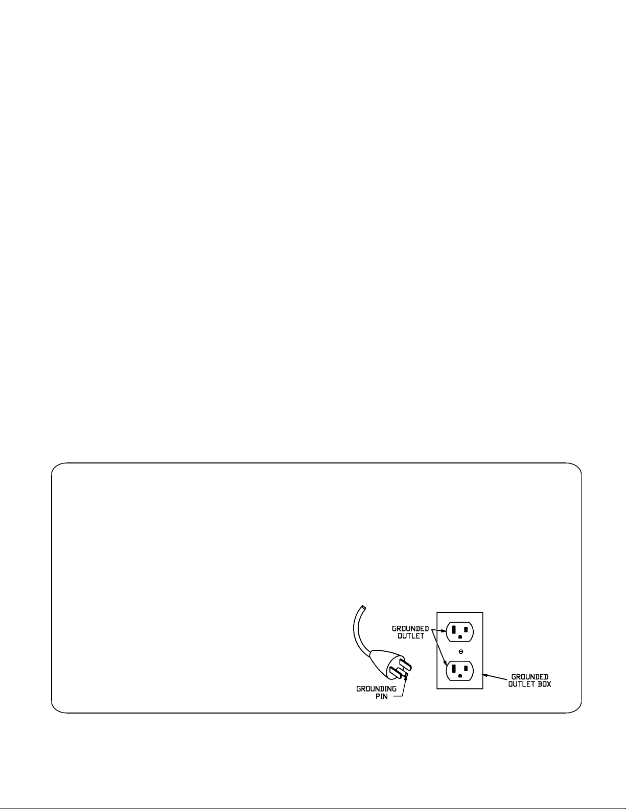
Use extreme caution when working around live electrical circuits. Failure to do so may result in
Use extreme caution when working around live electrical circuits. Failure to do so may result in Use extreme caution when working around live electrical circuits. Failure to do so may result in
Use extreme caution when working around live electrical circuits. Failure to do so may result in
death or serious injury.
death or serious injury.death or serious injury.
death or serious injury.
1
Inspect the condition of the TUF-Lugger™, checking for worn or damaged parts.
2
Have damaged par
Have damaged parHave damaged par
Have damaged parts replaced by an authorized service center. Any attempt to modify the TUF
ts replaced by an authorized service center. Any attempt to modify the TUFts replaced by an authorized service center. Any attempt to modify the TUF
ts replaced by an authorized service center. Any attempt to modify the TUF-
--
-
Lugger
LuggerLugger
Lugger
or use other than dcd replacement parts will void the warranty and may result in death
or use other than dcd replacement parts will void the warranty and may result in death or use other than dcd replacement parts will void the warranty and may result in death
or use other than dcd replacement parts will void the warranty and may result in death
or serious injury.
or serious injury.or serious injury.
or serious injury.
3
Examine the condition of the pulling rope. Check for contamination with mud, sand, or dirt.
Check for rust discoloration. Check for broken or worn strands.
Use a pulling rope with a maximum rated capacity that meets or exc
Use a pulling rope with a maximum rated capacity that meets or excUse a pulling rope with a maximum rated capacity that meets or exc
Use a pulling rope with a maximum rated capacity that meets or exceeds the TUF
eeds the TUFeeds the TUF
eeds the TUF-
--
-Lugger
LuggerLugger
Lugger
maximum pulling force of
maximum pulling force of maximum pulling force of
maximum pulling force of 5
55
5,500 lb. Failure to do so may result in death or serious injury.
,500 lb. Failure to do so may result in death or serious injury.,500 lb. Failure to do so may result in death or serious injury.
,500 lb. Failure to do so may result in death or serious injury.
Downgrade or discard pulling rope that has been subject to overload, or physical degradation.
Downgrade or discard pulling rope that has been subject to overload, or physical degradation. Downgrade or discard pulling rope that has been subject to overload, or physical degradation.
Downgrade or discard pulling rope that has been subject to overload, or physical degradation.
Failure to do so may result in death or serious injury.
Failure to do so may result in death or serious injury. Failure to do so may result in death or serious injury.
Failure to do so may result in death or serious injury.
5
[email protected] | 13309 Beach Ave. Marina del Rey, CA 90292 | wctproducts.com | Phone: 800-WCT-PROD (928-7763) or (310) 822-5212