Webb WEBV26 User manual

OPERATOR’S MANUAL & PARTSLIST
MODEL
WEBV26
FRONT COVER
Spares & Support: 01793 333212
Please read & understand this manual, paying particular attention to the safety
instructions, before use.
The manufacturer reserves the right to change the product specification and
livery according to continued product improvements.
193867001 20/11/2015


CONTENTS
SAFETY INSTRUCTIONS
SPECIFICATIONS
COMPONENTS
ASSEMBLY
OPERATION
MAINTENANCE, CLEANING & STORAGE
TROUBLE SHOOTING
PARTS DIAGRAM & LIST
DECLARATION OF CONFORMITY
WARRANTY

SAFETY INSTRUCTIONS
Read and understand the owner’s manual and labels affixed to the machine. Learn its application and
limitations as well as the specific potential hazards. Retain these instructions for future reference. The
operator is responsible for following the warnings & instructions in this manual and on the product.
Read & understand operator’s manual
before using the machine. Failure to
follow instructions could result in
death or serious injury.
This graphic and when accompanied by
WARNING or DANGER, calls attention
to actions which could lead to SERIOUS
INJURY
Always wear eye and ear protection
WARNING
Never modify a machine in any way.
Incorrect use of a machine can cause
SERIOUS OR FATAL PERSONAL INJURY
Always wear gloves to protect your
hands.
SHARP ROTATING BLADES
It is advisable to wear a face mask to
stop debris from entering your body.
Always TURN OFF THE ENGINE,
ensuring the cutting tool has stopped,
before cleaning, removing or adjusting
the machine tubes.
15m
Keep all bystanders & animals at least
15 metres away from the machine
during operation.
If approached, stop the machine
immediately.
No smoking
Risk of Carbon Monoxide Poisoning.
Ensure working area is correctly
ventilated.
Do not use near a flame, or sparks
Fire Risk
Fire and its vapors are extremely
flammable & explosive.
Fire or explosion can cause severe
burns or death.
Moving Parts
Rotating parts can contact or entangle
hands, feet, hair, clothing or
accessories.
Traumatic amputation or severe
laceration can result
Hot Surface.
Running engines produce heat. Engine
parts, especially the exhaust, become
extremely hot.
Severe thermal burns can occur on
contact
Safety alert symbol. Used to alert you to potential personal injury hazards. Obey all safety messages that
follow this symbol to avoid possible injury.
DANGER
Indicates an imminently hazardous situation which, if not avoided, will result in serious injury.
WARNING
Indicates a potentially hazardous situation which, if not avoided, could result in serious injury
CAUTION
Indicates a potentially hazardous situation which, if not avoided, may result in minor or moderate injury.
CAUTION
Used without the safety alert symbol indicates a potentially hazardous situation which, if not avoided, may
result in property damage.

STAY ALERT
Do not operate the machine while under the influence of drugs, alcohol, or any medication that could affect
your ability to use it properly. Do not use this machine when you are tired or distracted from the job at hand.
Be aware of what you are doing at all times. Use common sense.
AVOID DANGEROUS CONDITIONS
Make sure there is adequate surrounding workspace. Cluttered areas invite injuries.
Keep your work area clean with sufficient light. Keep area around the machine clear of obstructions, stones,
sticks, wires and other debris or foreign bodies which could cause damage to the machine.
DO NOT SMOKE, whilst using the machine.
INSPECT YOUR MACHINE
Check all bolts, nuts, and screws for tightness before each use, especially those securing guards and drive
mechanisms. Vibration during use may cause these to loosen.
Replace damaged, missing or failed parts before using.
Warning labels carry important information.
Replace any missing or damaged warning labels.
DRESS PROPERLY
Do not wear loose clothing, gloves, scarfs, neckties or jewelry (rings, wrist watches), which can be caught in
moving parts.
ALWAYS wear protective eye and ear wear. Appropriate gloves are also recommended.
Wear protective hair covering to contain long hair, preventing it from getting caught in machinery.
DO NOT use whilst barefoot or wearing open toed footwear.
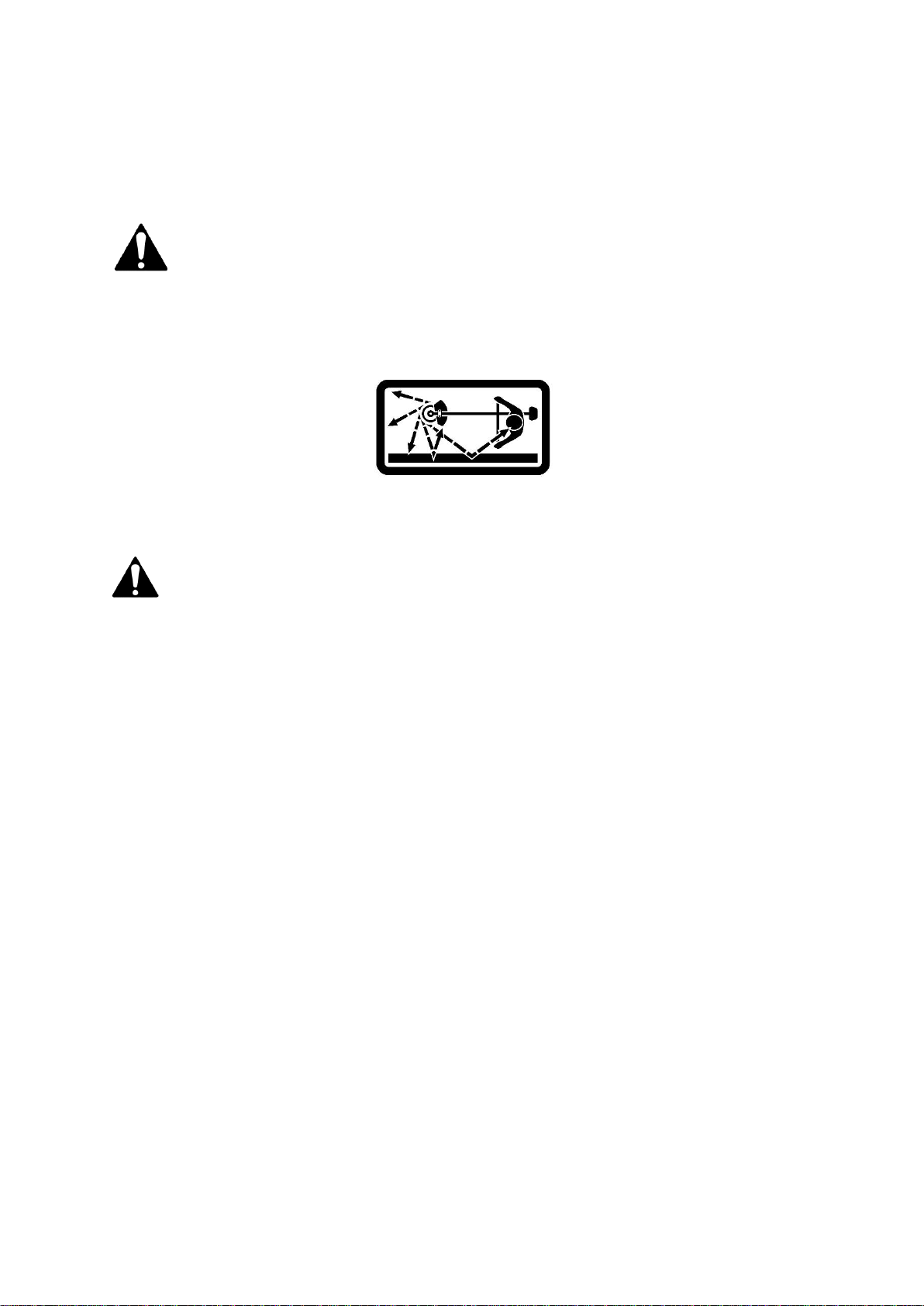
KEEP BYSTANDERS AND CHILDREN AWAY
Keep unauthorised persons or animals a minimum distance of 15 metres away from the mower. Do not allow
children to handle, use, or climb on the lawnmower.
DO NOT OVERREACH
Keep proper footing and balance at all times, particularly if using on slopes. The machine should not be used
on steep slopes and always be sure of footing.
AVOID INJURY FROM UNEXPECTED ACCIDENT
Keep hands out of the way of moving parts, particularly the engine and rotating cutting tool.
DO NOT FORCE TOOL
Always work within the rated capacity. Do not use the machine for a purpose for which it was not
intended. Always use the correct handles and shoulder straps provided with the machine.
MAINTAIN YOUR MACHINE WITH CARE
Clean the machine immediately after use. Keep the machine clean to ensure it operates to its full and safest
performance. When maintaining this machine, only the manufacturer’s original replacement parts should be
used. The use of non-original manufacturer parts may invalidate your warranty.
STORE IDLE EQUIPMENT
When not in use, the machine should be stored in a dry location. Keep the machine away from children and
others not qualified to use it. DO NOT STORE FUEL IN THE MACHINE, fuel over 30 days old can become stale
and if used, damage the carburetor, which is not covered by the manufacturer’s warranty.

SPECIFICATIONS
Model
WEBV26
Product Number
193867001
Engine (cc)
25.4
Idle Speed (r/min)
3000+200
Fuel Tank Capacity (Litre)
0.5
Fuel Ratio (Petrol:2 Stroke Oil)
25:1
Dimensions (mm)
L-580, W-355, H-370
Weight (kgs)
N.W 4.8 - G.W 7.8
The manufacturer reserves the right to change the product specification and livery according to continued
product improvements.
This symbol on the product or on its packaging indicates that this product may not be treated as household
waste. Instead it shall be handed over to the applicable collection point for the recycling of electrical and
electronic equipment.
For more detailed information about recycling of this product, please contact your local council office, your
household waste disposal service or shop where you purchased the product.

COMPONENTS
1. Blow Pipe A
2. Blow Pipe B
3. Collection Bag
4. Suction Pipe A
5. Suction Pipe B
6. Discharge Pipe
7. Fan Cover
8. On/Off Switch
9. Throttle Trigger
10. Air Filter Cover
11. Recoil Starter
12. Choke Lever
13. Fuel Tank
14. Fuel Cap
15. Spark Plug Cap
1
2
3
7
4
6
8
9
10
11
12
13
15
14
5

ASSEMBLY
Remove the machine and contents from the carton. Be sure the carton is empty before discarding.
If you require any assistance with regards to the contents of the lawnmower contact us:
Tel: 01793 333212 - Mon –Fri 8.30am –5.00pm (excl. Bank Holidays)
Email: customerservice@webblawnmowers.co.uk
VACUUM ASSEMBLY
1. Open the fan cover, by loosening the top screw and allowing the fan cover to open.
2. Match Suction Tube A, with the top & bottom locking stubs on the body of the machine.
3. Rotate the tube clockwise to lock into place.
4. Repeat the same actions, attaching Suction Tube B to Suction Tube A.
5. Insert the Discharge Tube into the Collection Bag and secure.
6. Connect the Discharge Tube to the Discharge Outlet of the machine and secure with an M5x10 screw

BLOWER ASSEMBLY
1. Match Blower Tube A, with the locking stubs on the body of the machine.
2. Rotate the tube clockwise to lock into place.
3. Repeat the same action attaching Blower Tube B to Blower Tube A.
4. Secure Blower Tube A to the body of the machine, using M5x10 screw.
WARNING
EXCESSIVE VIBRATION OF THE MULCHING FAN INDICATES IT HAS BEEN DAMAGED. CONSULT YOUR LOCAL
APPROVED DEALER FOR ASSISTANCE

OPERATION
DANGER
All model Blowers can throw small stones, metal or small objects as well as material. Do not allow anyone to
enter the operating DANGER ZONE with you. The danger zone is an area 15 metres in radius.
Insist that persons in the RISK ZONE beyond the danger zone wear eye protection from thrown objects. If
the unit must be used where there are unprotected people, operate at a low throttle speed to reduce the
risk of thrown objects.
DANGER ZONE WITHIN 15 METRES - RISK ZONE GREATER THAN 15 METRES
GENERAL USE
WARNING
Prior to using the machine, ensure all hardware (bolts, screws & nuts) are securely tightened.
Operate the trigger with your right hand & hold the Lower Handle with your left hand.
The trigger increases and decreases the power of the engine to the attachment, increasing the
revolution/reciprocation of the attachment.
WORKING PLAN
Blow material to a safe collection point, away from stones and other hard debris, which could damage the
mulching fan within the machine.
Limit the amount of time the product is used continuously to a maximum of 40 minutes per session.
Leave the machine to rest between sessions for between 10-20 minutes.
Total amount of work performed per day with the machine, should be limited to 120 minutes maximum.
Continuous use of the machine can cause “Repetitive Stress Injury (RSI)”. If you feel discomfort, redness or
swelling of your hands and fingers or any other body part, consult your doctor.
Check local regulations for sound level and hours of operation constraints.
Never transport the machine, whilst the engine is running.
USING THE VACUUM
When using the vacuum, ensure the bag is not damaged and the zip is in working order, to ensure debris is
not thrown.
When the bag is full, open the zip on the bag and tip the contents into a recycling bin or compost heap.
USING THE BLOWER
Always be aware of the strength and direction of the air stream.
Never direct the blower towards period or animals.

FUEL & OIL MIXTURE
Fuel & its vapors are very flammable. Do not use or fuel the machine near a flame, sparks or while smoking.
Allow the engine to cool for more than 2 minutes, before re-fueling. Never fuel the machine with the engine
running. Fuel the engine at least 3 metres away from your work area. Always fuel your machine outdoors.
Use good quality unleaded fuel which contains NO ETHANOL or METHANOL. Use Branded 89 octane or higher
unleaded fuel, known to be of good quality.
Fuel which is older than 30 days old can become stale and cause acid & gum deposits in the fuel system or
essential carburetor components. This could result in starting issues which would not be covered by your
manufacturer’s warranty.
To keep fuel fresh, we recommend you use Handy Parts –Sure Start Garden Machinery Fuel Additive which is
available in 250ml bottles, for 25 litres of fuel.
Helps makes machines easier to start
Extends shelf life of petrol up to 2 years
Keeps carburetor & engine clean
Reduces emissions & increases fuel economy
Only use 2-stroke air cooled engine oil. DO NOT USE automotive or marine oil.
It is recommended that you use a Fuel Mixing Bottle, to ensure the correct fuel mixture is used with your
machine. We recommend Handy Parts item HP-120. The fuel mixture should be shaken prior to entering the
machine fuel tank.
Mix only the quantity you require to complete your specific task.
FUEL MIXTURE RATIO - 25:1 (UNLEADED PETROL 25:1 2-STROKE MINERAL OIL)
IF USING SYNTHETIC OR SEMI SYNTHETIC OIL, CONSULT THE OIL MANUFACTURERS INSTRUCTIONS
25:1 FUEL MIXTURE RATIO
Unleaded
Petrol –litre
Two-Stroke
Mineral Oil - ml
1
40
2
80
3
120
4
160
5
200
Unscrew the machine fuel cap slowly and fill the fuel tank with your fuel mixture to a maximum of 80%
capacity. This will allow for fuel tank expansion.
Fasten the fuel cap tightly, being careful not to cross-thread. This will also prevent loosening through vibration
during use.
Wipe away any spillage, with an appropriate material.
If the machine has continued leaks, the product should not be started. Never use the machine with damaged
ignition cable or spark plug cap, as there is a risk of sparks.
IMPORTANT
Ensure that any stored petrol/oil mixture is clearly marked in a separate appropriate canister for a maximum
of 4-6 weeks.
If the machine is not going to be used for a long period, drain the mixture from the fuel tank, start the engine
and drain the carburetor of any remaining fuel. (See Maintenance for further instruction)
Dispose of any unwanted 2-stroke mixture at an authorised recycling point.

ENGINE STARTING & STOPPING PROCEDURE
STARTING A COLD ENGINE
1. Place the machine onto a flat, firm surface.
2. Keep the machine clear of any surrounding objects
3. Move the stop switch to "START" position
4. Give a gentle push on the primer pump repeatedly (7-10 times) until fuel comes into the primer pump.
5. Pull the Choke Lever up to close the choke
6. Whilst holding the machine down with your left hand, away from the engine and pull the engine recoil starter rope
vigorously, until the engine false starts.
(DO NOT LET THE RECOIL STARTER ROPE RETRACT BY ITSELF, FEED THE ROPE BACK INTO THE HOUSING)
7. Push the choke lever downwards (excessive cranking with choke lever up will cause the engine to flood, making it
difficult to start.)
8. Pull starter handle until engine starts.
9. Allow engine to warm up for a few minutes before using.
STARTING A WARM ENGINE
1. Move the switch to "START" position
2. If the fuel tank was run dry on previous operation, follow steps 3-7 of cold start procedure.
3. Whilst holding the machine down with your left hand, away from the engine and pull the engine recoil starter rope
vigorously, until the engine false starts.
STOPPING THE ENGINE
1. Move the stop switch to the “STOP” position
CHOKE LEVER
PRIMER BULB
Choke Closed
Cold Start
Position
Choke Open
Warm Start or
Run Position

MAINTENANCE, CLEANING & STORAGE
WARNING
Improper maintenance & storage of the machine may void your warranty.
Keep the machine clean for better and safer performance.
MAINTENANCE
Before each use, check all nuts & bolts to be sure they are sufficiently tightened.
We recommend only manufacturer original parts are used when maintaining this machine. Failure to do so could
invalidate your manufacturer’s warranty.
The engine must be switched off, with the spark plug cap removed, before the machine is unassembled, cleaned,
serviced or maintained.
ADJUSTING CARBURETOR
Do not adjust carburetor unless necessary. If you have trouble with the carburetor, see your dealer. Improper adjustment
may cause engine damage and void warranty.
SPARK PLUG
Check the Spark Plug after every 10-15 hours of use.
Remove the Spark Plug cap
Using the Spark Plug Spanner supplied, remove the Spark Plug by turning it anti-clockwise.
Clean & adjust the electrode gap to 0.6-0.7mm
If the Spark Plug is visibly damaged or worn, replace immediately (See Specification for details)
Install the new/cleaned Spark Plug to finger tightness, before fully tightening with the spanner.
CLEANING
Keep your machine clean.
Thoroughly clean the machine at the end of each use, paying particular attention to cuttings in and around the guard and
cutting tool.
AIR FILTER
Accumulated dust in the air filter will reduce engine efficiency, increase fuel consumption and allow abrasive particles to
pass in the engine. Remove & clean the air filter regularly to ensure optimum performance.
Remove the air filter cover, by releasing the securing winged screw from the front of the cover.
Lift off the cover.
Remove the sponge air filter from the housing.
Tap the filter to remove light surface dust.
Heavy deposits should be washed out of the Air Filter in soapy water. Allow the filter to dry completely.
FUEL FILTER
The fuel tank is fitted with a filter. It is situated at the free end of fuel pipe and can be picked out through the fuel filler
neck, with a piece of hooked wire or similar.
Check the fuel filter periodically. Do not allow dust to enter into the fuel tank. A clogged filter will cause difficulty in
starting the engine or abnormalities in engine performance.
When the filter is dirty, replace the filter.
When the inside of the fuel tank is dirty, it can be cleaned by rinsing the tank out with petrol.
SUCTION & BLOWER TUBES
It is advisable to remove the Suction & Blower tubes from the machine regularly for cleaning.
Use Soapy water to remove any dirt or grime.

STORAGE
For years of trouble free service, make sure the machine is clean and dry before storing.
Before storing, clean the machine thoroughly as indicated above.
Store indoors or in a safe, locked protected area during severe weather and winter months.
DO NOT STORE in an enclosed area, where fuel vapors can reach an open hot flame.
DO NOT STORE fuel in the machine. Ensure fuel is removed from the fuel tank and carburetor.
If storing for an extended period, inspect, clean and repair the machine if necessary. Remove all fuel from the fuel tank.
Start the engine, this will remove all fuel from the carburetor and fuel lines. Remove the spark plug, pour a small
quantity of 2-stroke oil into the spark plug hole of the cylinder and re-seat spark plug. Store in a clean, dry, dust free
area.
DO NOT STORE fuel for longer than 30 days. Fuel can become stale and cause damage to the engine carburetor, which is
not covered by the machines manufacturer’s warranty.
TROUBLE SHOOTING
Failures such as a difficulty in starting the engine, irregularity in functions and abnormality in performance can normally be
prevented if careful attention is paid to all operating instructions and maintenance procedures.
Should the engine not function properly, check the following?
That the fuel system is in good condition and fuel is flowing to the engine.
The ignition system is in good condition and the spark plug, sparks correctly.
Compression of the engine is adequate.
FAILURE TO START
Correctly follow the starting procedure, not setting the choke lever or priming the engine can cause the engine to not
start.
Dispose of fuel from the tank, particularly if over 30 days old.
Ensure that fuel is fresh and clean.
Check fuel filter to ensure it is clean. (Replace filter if necessary).
Make sure air filter elements are clean.
Install a new, properly gapped spark plug.
When there is serious trouble with the unit, do not try to repair it yourself, but have your local approved service dealer
inspect it for you.

PARTS DIAGRAM - WEBV26 Engine

PARTS LIST - WEBV26 Engine
Item No
Webb Part No.
Handy Description
Qty
Item No
Webb Part No.
Handy Description
Qty
1
WE03130010013
Spark Plug RCJ6Y
1
24
WE02050030018
Flywheel
1
2
WE03010010061
Bolt M5X20
4
25
WE02070010078
Insulator Gasket
1
3
WE70070130011
Cylinder
1
26
WE02110030031
Insulator
1
4
WE02070010020
Cylinder Gasket
1
27
WE03020020012
Bolt M5X20
2
5
WE02020020003
Piston Ring
2
28
WE02070010061
Carburretor Gasket
1
6
WE02010020006
Piston
1
29
WE02050020045
Carburetor
1
7
WE02020010004
Piston Pin 8X28
1
30
WE70030040038
Choke Lever
1
8
WE02020030017
Snap Ring
2
31
WE70080120007
Air filter Housing
1
9
WE03090020018
Needle Bearing
1
32
WE70030040028
Choke
1
10
WE02020150007
Thrust Washer
2
33
WE03010040008
Bolt ST4×10
1
11
WE02020120026
Crankshaft Assembly
1
34
WE02090010011
Air filter Housing
1
12
WE03090010028
Bearing 6001/P5
2
35
WE03020020030
Bolt M5X60
2
13
WE03060010002
Pin B3X10
2
36
WE70030040078
Air Filter Cover
1
14
WE02070010110
Crankcase Gasket
1
37
WE70030180012
Air Filter Screw
1
15
WE03050010014
Rear Crankcase
1
38
WE02070010141
Exhaust Gasket
1
16
WE03100010009
Oil Seal 12X22X7
2
39
WE02050010018
Exhaust
1
17
WE03120030003
Stop Ring
2
40
WE03040020019
Washer 5
2
18
WE02050100015
Starter Pawl
1
41
WE03050010014
Washer 5
3
19
WE02020110088
Starter Pawl Spring
2
42
WE03010010049
Screw M5X50
2
20
WE70030140015
Starter Pawl
2
43
WE03040010007
Washer 4
2
21
WE03070010002
Woodruff Key
1
44
WE02070010048
Spacer
2
22
WE70070050001
Crankcase - Front
1
45
WE02050050141
Stop Wire
1
23
WE03010010045
Bolt M5X30
3
46
WE02050030024
Ignition Coil
1
47
WE03020020013
Screw M4X20
2

PARTS DIAGRAM - WEBV26 Machine

PARTS LIST - WEBV26 Machine
Item No
Part No.
Description
Qty
Item No
Part No.
Description
Qty
1
WE70050010068
Tube A
1
32
WE03010040017
Screw ST4.2×10
1
2
WE70050010069
Tube B
1
33
WE02050050171
Stop Wire
1
3
WE03010060056
Screw M5×16
3
34
WE51010040002
Engine
1
4
WE03040020020
Washer 5
11
35
WE03040050022
Washer
1
5
WE70030030284
Connect Cover
1
36
WE02060020003
Recoil Pulley
1
6
WE03010060078
Screw M5×10
6
37
WE02060020009
Recoil Spring
1
7
WE70030180100
Safety Cover
1
38
WE'70080100004
Housing
1
8
WE02050050002
Safety Switch
1
39
WE03020020041
Screw M5×30
3
9
WE70030070032
Button Connector
1
40
WE01050010009
Recoil Rope
1
10
WE03040050017
Washer 6
1
41
WE70030140010
Recoil Handle
1
11
WE70030180012
Fan Cover Screw
1
42
WE70050010070
Curved tube
1
12
WE70030030303
Dan Cover
1
43
WE02050040087
Throttle Wire
1
13
WE02020160312
Spring shaft
1
44
WE02050060050
Collection Bag
1
14
WE02020110048
Spring
1
45
WE02050060022
Harness
1
15
WE70030010071
Rear Case
1
46
WE01040010003
Return Fuel Pipe(L=70)
1
16
WE03030020002
Nut M8×1
1
47
WE02080030025
Fuel Pipe Rubber Bung
1
17
WE02020070042
Shatter Tooth
1
48
WE01040010014
Inlet Fuel Pipe(L=220)
1
18
WE70030090006
Impellor
1
49
WE02050120002
Fuel Filter
1
19
WE03010010045
Screw M5×30
4
50
WE02110020026
Fuel Cap Assembly
1
20
WE02080020046
Left Handle Rubber Cover
1
51
WE03050010007
Washer 8
1
21
WE70030010055
Front Case
1
52
WE03040050005
Washer 23*8*1
1
22
WE02020160117
Pedestal
4
53
WE70050010066
Tube C
1
23
WE70050030063
Fuel Tank
1
54
WE70050010067
Tube D
1
24
WE'03010040057
Screw M5*20
4
55
WE02050070048
Recoil Rope Guide
1
25
WE70030160093
Lower Handle
1
56
WE02040030020
Bush
1
26
WE02020160398
Throttle Lever Shaft
1
57
WE02080030015
Wire Lead
1
27
WE70030070109
Throttle Lever Handle
1
58
WE03110020023
“O” Sealing Washer 25x2
1
28
WE02050050111
Stop Switch
1
59
WE03010060076
Screw M5×30
2
29
WE02050050171
Short Stop Wire
2
60
WE03020020018
Screw M5×10
1
30
WE70030160048
Upper Handl;e
1
61
WE03050010015
Washer 5
4
31
WE02080020046
Right Handle Rubber Cover
1
62
WE'03010040048
Screw NST5x16
11

EC DECLARATION OF CONFORMITY
We Handy Distribution Ltd - SN3 5HY (Importer) declare that the product:
Designation: Petrol Blower & Vacuum
Model(s): WEBV26
Type/Serial No. As per rating label on machine
Complies with the following directives:
Machinery Directive as last amended by EC Directive 2006/42/EC
The conformity assessment procedure followed was in accordance with
EN ISO 12100-2/A1:2009
EN 15503:2009
Blower
Measured Sound Pressure Level: LPA = 95.7dB(A)
Measured Sound Power Level: LWA = 112dB(A)
Vacuum
Measured Sound Pressure Level: LPA = 94.7dB(A)
Measured Sound Power Level: LWA = 111dB(A)
Notified Body:
TÜV SÜD Product Service GmbH
Addresses:
-10 Huaxia Road(m), Dongting, Wuxi, Jiangsu, 214100 (P.R China)
-Zertifizierselle, Ridlerstraße 65, 80339 München, Germany
Authorised signatory and technical file holder
Date: 10/11/2015
Signature:
Name: Mr Simon Belcher
Position: Managing Director
Company: Handy Distribution Ltd
Address: Murdock Rd, Swindon, Wiltshire, SN3 5HY.
Other manuals for WEBV26
2
This manual suits for next models
1
Table of contents
Other Webb Blower manuals
Popular Blower manuals by other brands

Tennant
Tennant 800 Operator's manual

GreenWorks
GreenWorks BL40L511 Operator's manual

Homelite
Homelite VAC ATTACK II UT08042 Repair sheet

Ariens
Ariens Power Brush 36 Operator's manual

Chicago Electric
Chicago Electric 96503 Set up and operating instructions

Cincinnati Fan
Cincinnati Fan PB Operating & maintenance instructions