Weco MX Series User manual

MX Series
Water Engineering Corporation
Long Beach, CA U.S.A
1 (888) 675-5187
WECO Reverse Osmosis
Drinking Water Filter
System Manual
www.wecofilters.com

Inspect the System before Installation:
Please inspect the System and all connection fittings carefully, and make sure there is no damage
during shipping. If you find a damaged or broken part, please DO NOT proceed with the installation,
and contact us for a replacement, broken part or assistance via 1 (888) 675-5187
General Installation and Maintenance Requirements:
•
Please make sure that the installation complies with State and local laws and regulations.
•
Do not use with the water that is microbiologically unsafe or of unknown quality without
adequate disinfection before or after system.
•
System must be installed indoors.
•
It is recommended that installation of the water filter be done by a professional plumber.
Important !
1
MX-SET2
It is recommended to change the 2 pre-filters at least every
3-5 months. It is advised to change them on time to avoid any
damages to the RO System. It is advised to use WECO replacement
filters. Using ‘non-WECO’ and poor quality filters may clog the
RO system and will also damage the membrane.
Visit us on www.wecofilters.com or call us at 1 (888) 675-5187
MX Manual
© 2017 Water Engineering Corporation

MX Manual
© 2017 Water Engineering Corporation
2
CARBON
PRE-FILTER
SEDIMENT
PRE-FILTER
3rd Stage
WECO COMMERCIAL RO
MEMBRANE
AUTO SHUT-OFF
VALVE
ALKALINE OR
UV SYSTEMS ONLY
5th Stage Filter
WECO PRODUCT
WATER TANK
4th Stage Filter
2nd Stage 1st Stage
MAIN SUPPLY
WATER
FILTERED
WATER
BRINE
Feed Water
IN OUT
Product Water
Flow Restrictor Check Valve
INLET
Water supply adapter valve
Cold water shut-off valve
Auxiliary faucet
Garbage disposal
Carbon Filters
Drain Saddle
Storage tank with valve in open Position
Sediment Filter
Membrane
Inline GAC Filter
Alkaline/UV Filter (optional)
A
B
C
D
A
E
F
G
H
I
J
K
A
B
C
D
E
F
G
H
I
J
K
Reverse Osmosis System Tubing Diagram
Fig. #1

3
Water supply adapter valve
Cold water shut-off valve
Auxiliary faucet
Garbage disposal
Carbon Filters
Drain Saddle
Storage tank with valve in open Position
Sediment Filter
Membrane
Inline GAC Filter
Alkaline/UV Filter (optional)
CARBON
PRE-FILTER
SEDIMENT
PRE-FILTER
PUMP
ALKALINE OR
UV SYSTEMS ONLY
5th Stage Filter
4th Stage Filter
2nd Stage 1st Stage
MAIN SUPPLY
WATER
FILTERED
WATER
BRINE
Feed Water
Product Water
INLET
Low-Pressure
Switch
Inlet Water
Solenoid Valve
High-Pressure
Switch Flow Restrictor
Check Valve
WECO PRODUCT
WATER TANK
3rd Stage
WECO COMMERCIAL RO
MEMBRANE
A
B
C
D
E
F
G
H
I
J
K
A
B
C
D
F
G
H
I
J
K
E
Reverse Osmosis System Electric Booster Pump Tubing Diagram
Electrical Diagram
Fig. #2
Fig. #3
MX Manual
© 2017 Water Engineering Corporation
Transformer
Solenoid
PUMP
110V-240V
AC
24V
DC
High-Pressure
Switch
Low-Pressure
Switch

4
CARBON
PRE-FILTER
SEDIMENT
PRE-FILTER
AUTO SHUT-OFF
VALVE
ALKALINE OR
UV SYSTEMS ONLY
5th Stage Filter
4th Stage Filter
2nd Stage 1st Stage
MAIN SUPPLY
WATER
FILTERED
WATER
BRINE
Feed Water
IN OUT
PERMEATA
IN
PERMEATA
OUT
BRINE
OUT
Product Water
Flow Restrictor
Check Valve
INLET INLET
BRINE
IN
WECO PRODUCT
WATER TANK
3rd Stage
WECO COMMERCIAL RO
MEMBRANE
Water supply adapter valve
Cold water shut-off valve
Auxiliary faucet
Garbage disposal
Carbon Filters
Drain Saddle
Storage tank with valve in open Position
Sediment Filter
Membrane
Inline GAC Filter
Alkaline/UV Filter (optional)
Permeate Pump
L
L
Reverse Osmosis System Electric Diagram with Permeate Pump
Fig. #4
A
B
C
D
A
E
F
G
H
I
J
A
K
A
B
C
D
F
G
H
I
J
K
E
MX Manual
© 2017 Water Engineering Corporation

Tapping into the cold water line
(Using the water supply adapter model FW 1)
Drilling the hole for the faucet
1. For best results, a ½” carbide-tipped drill bit should be used to drill a hole into your sink for the
auxiliary faucet.
2. Carefully select the faucet location making sure it will have a neat water fall pattern and that
the faucet stud will be accessible from below once the hole is completed.
3. For Porcelain Sink: Before starting the drill motor, apply firm downward pressure on the bit until
a crunching occurs. This will help keep the drill bit from moving.
4. For Stainless Steel Sink: Before using a ½” carbide drill bit, an indent should be made with a
center punch to keep the drill bit from moving. A small pilot hole will also aid the ½” drill bit.
5. For best results, keep steady firm pressure during the start of the hole will cause excess wear
on the bit and progress will be slow.
6. Once the hole is complete, clean the area of metal chips and roughness around the hole.
Metal chips will stain Porcelain.
5
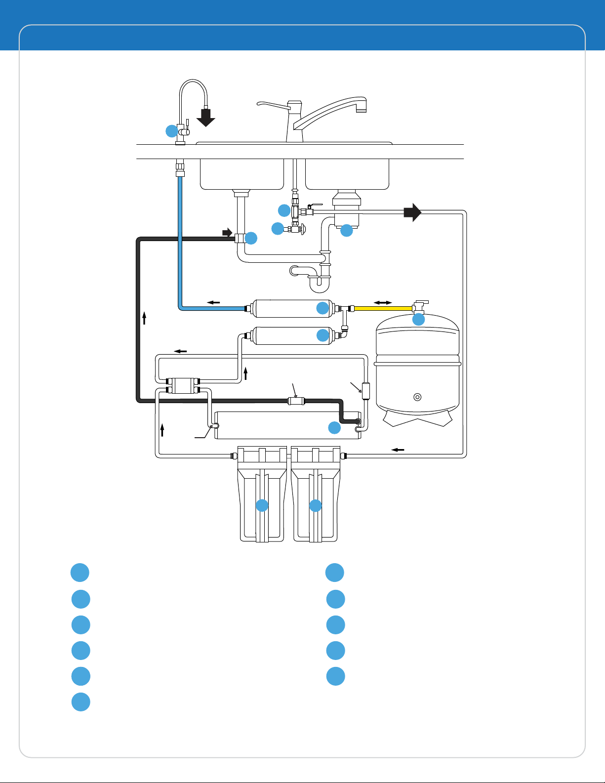
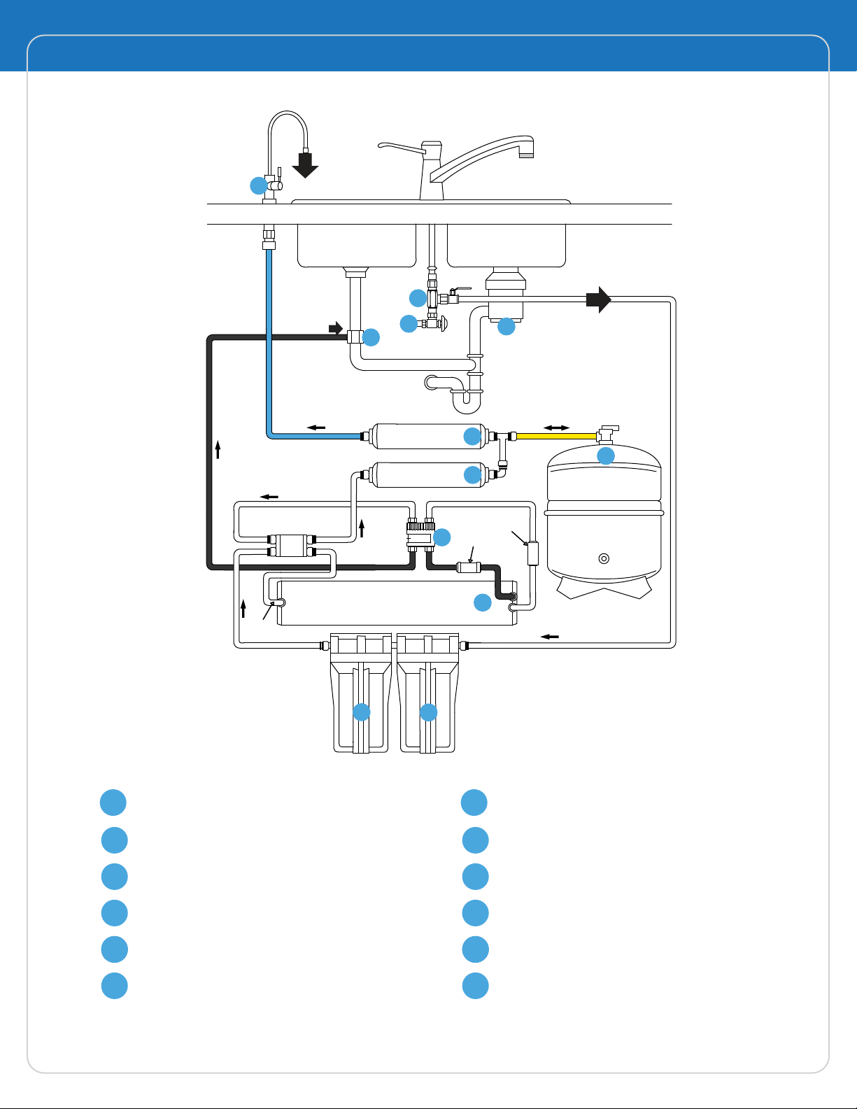
NOTE: The drinking water system must be connected to the COLD
water supply only.
1. Turn off the cold water supply to the sink faucet
by locating the Round or oblong handle on the
right side of the sink cabinet and Turning clockwise
until the water supply is off.
NOTE: If the cold water shut-off valve fails to turn off the water, the
house water supply can be turned off at the main water supply.
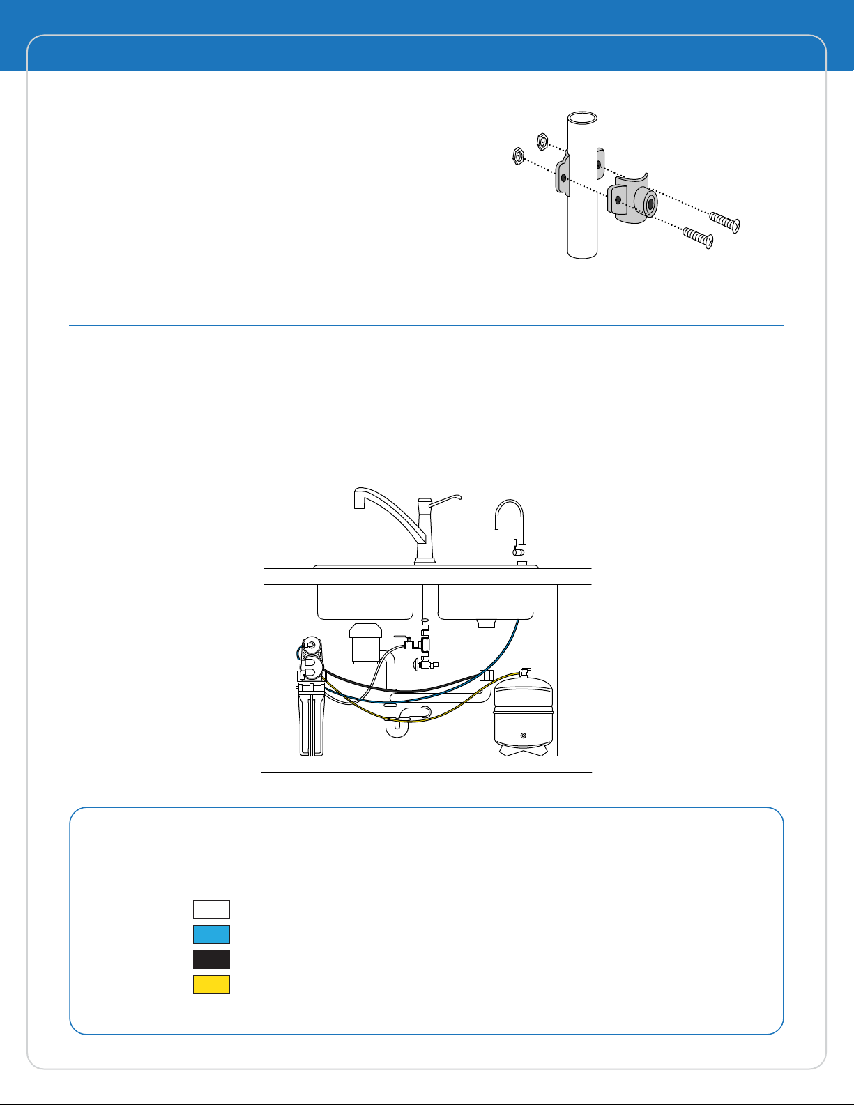
2. The water supply adapter can be installed at the faucet Connection (A of Fig. #5) of the cold
water line or at the shut-off Valve connection (B of Fig. #5).
3. Disconnect the threaded nut at the connection and thread the water supply adapter, with
the flat washer in place, onto the connection and tighten. Connect the white tubing to the
water supply adapter with the treaded nut and tighten.
4. Thread the needle valve into the adapter tightly and turn the handle clockwise all the way in.
Turn on cold water supply to the sink faucet and check for leaks.
NOTE: Safety glasses should be worn to protect your eyes while drilling the faucet hole.
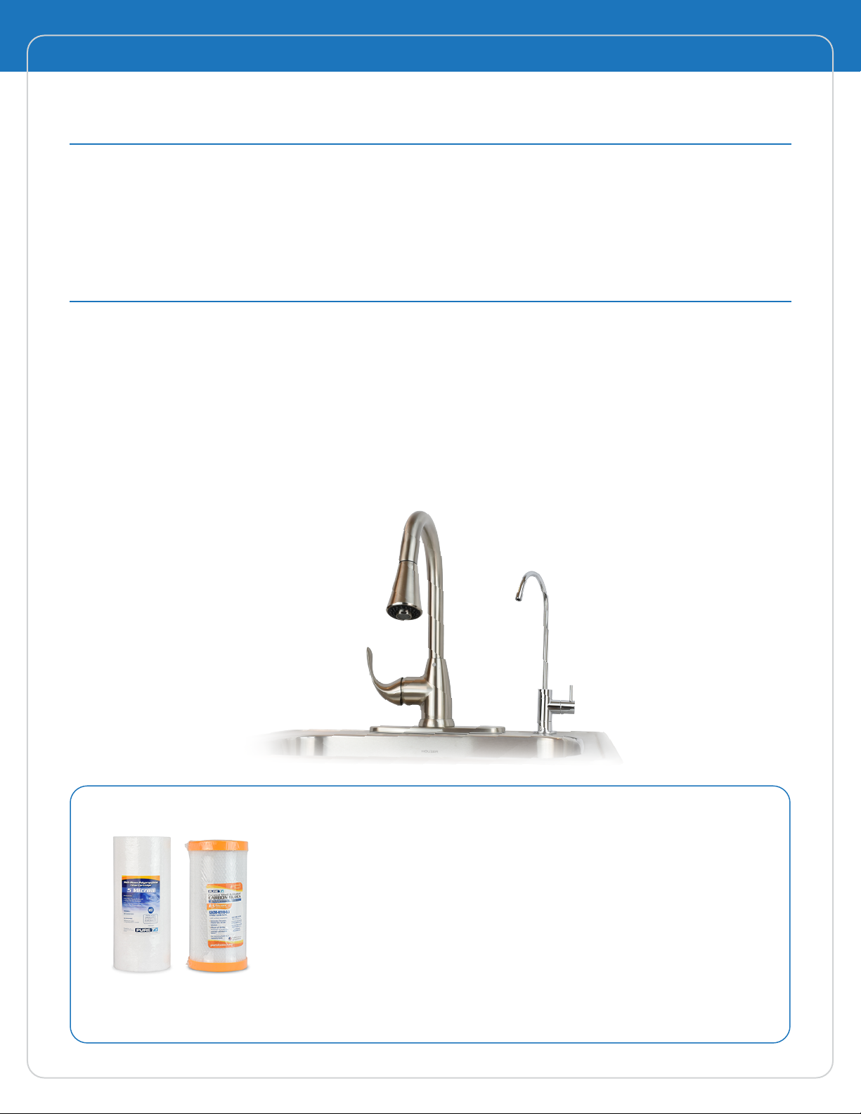
INSTALLATION INSTRUCTIONS
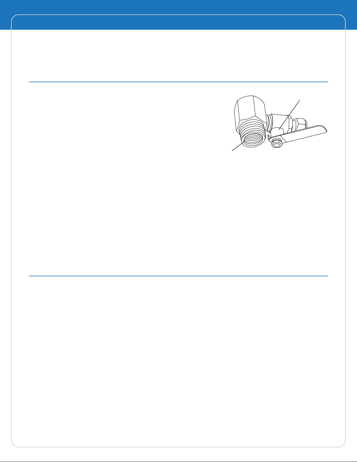
NEEDLE VALVE
WATER SUPPLY
ADAPTER
Fig. #5
MX Manual
© 2017 Water Engineering Corporation

Mounting the faucet
Your unit comes complete with a long reach faucet.
Drain clamp installation
1. The drain clamp assembly should be installed above the trap and on the vertical or horizontal
tailpiece (Fig. #7)
6
NOTE: Air gap option installation instructions are available upon
request. The following instructions is for non-air gap option.
1. Slide chrome cover plate and rubber gasket onto
stem of faucet and place faucet onto sink with the
stem going through the hole.
2. Place metal washer and lock washer over threaded
stem of faucet and tighten nut from under the
counter surface to lock the faucet into place.
DO NOT OVER TIGHTEN.
3. Connect the blue tube to the faucet stem under
the counter and tighten.
Fig. #6
2. Mark the hole position on the pipe and drill a ¼” hole through one side of the pipe (Fig. #8).
Fig. #7
Fig. #8
Chrome Washer
Rubber Gasket
Star Lock Washer
Plastic Inlet Nipple
Plastic Sleeve
Compression Nut
Inlet Line
Brass Nut
Washer
Mount Drain
Saddleat Either
Location
Never
Mount
Here
MX Manual
© 2017 Water Engineering Corporation

Positioning the system
1. The head assembly will stand up in the sink cabinet or can be hung on screws provided.
2. The storage tank may be laid on its side.
3. The head assembly and/or storage tank maybe placed up to 15 feet from the point of use
with nominal pressure loss.
7
3. Make sure to align drain saddle to drilled hole.
Attach drain clamp to drain pipe and tighten
the two screws evenly. (Fig. # 9)
NOTE: The center hole on the sponge must be removed.
4. Connect the Black tubing to the drain clamp.
Fig. #9
CONNECTING THE SYSTEM
Use the color coded tubing to make the following connections:
• The white tubing connects the water supply adapter to the inlet side.
• The blue tubing connects the faucet to the outlet side.
• The Black tubing connects to the drain clamps.
• Tha yellow tubing connects the storage tank to the inlet side of the post
carbon.
Fig. #10
MX Manual
© 2017 Water Engineering Corporation

1. Check to see all connections are made
2. Check that the pre-filter and pre-carbon sumps are secure using the housing wrench provided.
3. Slowly turn on the water by turning the needle valve counterclockwise.
4. The valve handle on top of the tank should be in the open position, parallel to the valve body
5. The handle of the faucet should be perpendicular to the spigot (closed).
6. Check for leaks.
7. The RO/NF ro drinking water system makes 2 gallons of drinking water per hour and requires
1 to 2 hours before water is readily available.
8. During this initial fill period, you will hear water being discharged through the black drain line.
This is normal as the contaminated water is being rejected by the reverse osmosis membrane.
8
START-UP PROCEDURE
DO NOT DRINK THE WATER FROM THE FIRST TANK PRODUCED BY THE SYSTEM.
DISCHARGE THE WATER FROM THE STORAGE TANK BY OPENING THE FAUCET.
DISCHARGING MIGHT TAKE UP TO 15 MINUTES.
If you have any difficulties with the installation, or require additional information on your unit,
please consult with our factory technicians.
We thank you for purchasing our Reverse Osmosis / Nanofiltration unit for your high quality processed drinking
water. In order to maintain this high quality water, it is important that scheduled maintenance be followed.
MX Manual
© 2017 Water Engineering Corporation

DM-2 Digital TDS Monitor
Usage
The DM-2 is an ideal monitor to know if the membrane in WECO reverse osmosis is functioning
effectively. Activate the DM-2 so you’ll always know how the water purification system is
performing.
1. Press the “POWER” button.
2. To display the TDS level of the feed (tap) water, press the IN button. To display the TDS level of
the product (filtered) water, press the OUT button.
3. The displayed TDS will be most accurate after approximately 10 seconds.
4. Determining filter effectiveness depends on your particular system. For an RO system, for
example, compare the IN water TDS levels with the OUT water TDS.
5. If the “x10” icon appears, this means the TDS level is above 999 ppm. Therefore, multiply the
reading by 10. For example, if the display shows 143 ppm with the ‘x10’ icon, the actual TDS
level is 1430 ppm. (If the ‘x10’ icon does not appear, the reading on the display is the actual
TDS level.)
6. Turn off the unit. It will automatically shut off after 30 seconds.
9MX Manual
© 2017 Water Engineering Corporation
Dual TDS meter 2
AUTO SHUT-OFF
IN OUT
IN OUT
PPM

10
MX Manual
Calibration
Your monitor was factory calibrated to 342 ppm. This level is suitable for most tap water/filtered
water applications, so it is ready to use out of the box. However, you may need to re-calibrate
based on your needs, as well as from time-to-time to ensure best results. To calibrate:
1. Purchase a certified calibration solution that is correct for your needs. The calibration solution
should be NaCl. HM Digital’s 342 ppm NaCl is recommended.
2. Disconnect both T-fittings from their tubes. Do not remove the sensor from the T! Ensure the
orientation of the sensor to the fitting is correct, as in illustration #1. Shake any water out.
3. For better accuracy, calibrate to a flowing solution. If this is not possible, you can calibrate to
a still solution. Turn on the monitor and place each T-fitting (with the sensors in them) into the
calibration solution. You will get a reading. Ensure the fitting is completely filled with solution
and there are no air bubbles. This step is critical for proper calibration.
4. If the reading on the monitor (for either line) does not match the solution, adjust the reading up
or down by gently turning the plastic orange screws on the rear of the unit clockwise or
counterclockwise to raise or lower the reading.
5. Adjust the screws marked IN and OUT for their respective lines for large changes in calibration.
6. Adjust the screw on the lower-right corner for fine-tuning (for both IN and OUT).
7. If calibrating to a still (not flowing) solution, calibrate to 3% above the level of the calibration s
olution. This will accomodate for the lack of flowing water, which the monitor is programmed
for. For example, if the calibration solution is 342 ppm, adjust the screws until it reads 352 ppm.
If you are calibrating to a flowing solution, calibrate to the level of the solution.
8. Your monitor is now calibrated. There is no need to do anything else.
CARE AND MAINTENANCE
Very little care is necessary for your DM-2
• Never touch the sensor pins, as skin oils may adversely affect the TDS measurement.
• To clean the sensor pins, clean with rubbing alcohol and let air dry.
• Avoid removing the fittings, as doing this often may strip the plastic off the sensor and
potentially cause a leak.
• If you notice the readings are off from what they should be, replace the batteries or
re-calibrate
© 2017 Water Engineering Corporation

Changing the Batteries
If the display is fading or the readings are incorrect, you may need to change the batteries.
1. Unscrew the four metal screws (not the orange plastic screws) on the rear of the unit and
remove the back panel.
2. Remove the batteries.
3. Replace both batteries with two fresh AA batteries. Ensure the polarity is correct.
4. Close the back panel and replace the screws. You will not need to recalibrate.
TDS Monitor Specifications
TDS Range: 0-9990 ppm
Resolution: 0-999: 1 ppm
1000-9990: 10 ppm (indicated by a blinking ‘x10’ icon)
Accuracy: +/-2%
Conversion Factor: NaCl (avg. of 0.5)
Factory Calibration: 342 ppm NaCl
Sensor Cable Length: 46” (116.8 cm) (including sensor)
Power Source: 2 x AA batteries
Auto Shut-Off: After 30 seconds
Battery Life: Approximately 12-18 months
Base Unit Dimensions: 4.6 x 2.6 x 0.7 in (11.6 x 6.8 x 1.8 cm)
Base Unit Weight: 7.9 oz (224.3 g) (including batteries)
To properly maintain your WECO drinking water system, please use
only genuine WECO water replacement filters at
www.wecofilters.com or call us at 1 (888) 675-5187
RECOMMENDED SYSTEM MAINTENANCE
x10
PPM
TDS Level
Times 10 indicator
(appears if over 999 ppm)
Parts per million (equivalent to mg/L)
11 MX Manual
© 2017 Water Engineering Corporation

Reverse Osmosis Systems Replacement Cartridges
Sediment Pre-filter: The pre-filter protects the system and should
be maintained regularly, a clear housing has been provided for your
convenience. The show-white pre-Filter should be changed when the
outside discolors to a cardboard brown color and before the inner
surface discolors. The life of the pre- filter will depend upon the
condition of your water supply and should be checked at 3-month
intervals until a filter life is established (average life 6 months).
Carbon Block: Designed to remove chlorine form the water supply,
as well as organic and inorganic substance before entering the TFC
membrane (average life 12 months).
Post-Carbon: The post-filter should be
changed when you experience an unusual
taste and/or odor to the water and has a
nominal life of 1 year.
Membrane: The high quality Thin Film
Composite membrane should last between
2 to 4 years depending on the quality of your
local water.
MX-350 BVB09870005 CBCM-4510-0.5 TF-3012-500 ICF-10Q -
MX-350ALX BVB09870005 CBCM-4510-0.5 TF-3012-500 ICF-10Q ICF-2512-ALX
MX-350UV BVB09870005 CBCM-4510-0.5 TF-3012-500 ICF-10Q GL10SE4P
MX-500PMP BVB09870005 CBCM-4510-0.5 TF-3012-500 ICF-10Q -
System Stage 1 Filter Stage 2 Filter Stage 3 Filter Stage 4 Filter Stage 5 Filter
Drain your storage tank twice each month to extend the membrane life and have the freshest water
in the storage tank. Drain the storage tank by lifting the faucet handle into the parallel position
with the spigot until water flow stops from the tank. Return the faucet handle to the closed position
and the tank will refill in 2 hours. It is best to drain the system before retiring for the evening.
Complete Replacement Filter Kits Available.
Contact WECO for more details.
12
MX Manual
© 2017 Water Engineering Corporation

1. Turn OFF cold water supply to RO system. Turn OFF tank’s ball-valve. Lift up RO faucet lever
briefly to relief the built-up pressure inside the RO system. This will make opening the housings
easier.
2. Open housing: Have the RO standing upright. Slip the plastic wrench onto the #1 housing.
Looking down from a top view, you should open the housing turning clockwise. If necessary,
lay RO down on the floor to get a better leverage. If the housing is too tight, use a hammer
and tap on the wrench handle to help turn the wrench.
3. Discard used filters, wash housings with mild soap, rinse off. Put new filters cartridges into their
respective housings: sediment filter in stage-1, carbon block filter in stages 2.
4. Close up the housings. Make sure each housing has a black O-ring in the thread groves. Use
wrench to tighten each housing.
5. Remember: Turn ON the cold water supply and OPEN the tank valve after finished changing
filters!
6. Check for leaks!
CHANGING THE PRE-FILTERS
1. Shut off the feed water to the system by turning the saddle valve on the water supply adapter
clockwise until it stops.
2. Close the storage tank ball valve by turning the handle perpendicular to the valve body.
3. Open the drinking water faucet relive pressure.
4. Allow 3-5 minutes for pressure in the system to drop.
5. Disconnect the tubing from the membrane cap by pushing in and holding down the end
collar ring surrounding the quick connect elbow fitting while gently pulling back on the tubing.
6. Remove the membrane housing cap by turning counter-clockwise.
7. Using a pair of needle nose pliers, remove and discard the used membrane.
8. Rinse the inside of membrane housing with warm water.
9. Using pliers, insert the new membrane all the way into the housing (double o-ring end first),
making sure it is properly seated.
10. Replace and hand-tighten the membrane housing cap by turning clockwise.
11. Reconnect the removed tubing by pushing it into the elbow fitting in the housing cap.
12. Gently pull back on the tubing to insure a leak free connection.
CHANGING THE MEMBRANE
CAUTION: ANY REPLACEMENT FILTERS OR MEMBRANE NOT RECOMMENDED BY THE
FACTORY CAN CAUSE SEVERE DAMAGE TO THE SYSTEM AND VOIDS ALL WARRANTIES.
13 MX Manual
© 2017 Water Engineering Corporation

OPERATING LIMITS
Max. TDS Water
Temperature pH Range Water
Pressure
Standard
RO System
RO with
Booster Pump
2000 ppm 40 - 85 F 2 - 11 45 - 85 PSI
o
2000 ppm 40 - 85 F 2 - 11 5 -30 PSI
o
TF-3012 Reverse Osmosis Membrane Specifications
AXEON TF-3012-500 Reverse Osmosis (RO) Membrane for light commercial membrane systems is one of
the most reliable and consistent elements in the industry. Utilizing HF5 advanced membrane technology,
the new TF-3012 500 membrane offers an exceptional balance of high flow rates and salt rejection tates.
Part
Number
208802 TF-3012-500 70 (4.8) 500 (79) 98.0
Description
Applied
Pressure
psi (bar)
Permeate
Flow Rate
gpd (lph)
Nominal
Rejection
(%)
Specifications
TF-3012-500 11.75 /
298.50
Description A B C D E
Membrane Dimensions (in/mm)
11.00 /
298.50 0.79 /
20.01 0.75 /
20.01 2.95 /
74.93
Test Parameters: 250 TDS Filtered (5 Micron), De-Chlorinated, Municipal Feed
Water, 77°F, 40% Permeate Recovery, 6.5 - 7.0 pH Range, at the Specified
Operating Pressure. Data Taken After 30 Minutes of Operation. Maximum
Pressure drop for each Element is 10 psi. Minimum Salt Rejection is 96%.
Permeate Flow for Individual Elements may vary +/- 20%.
Wet tested membrane elements must be kept sealed and moist while in
storage. Drying out may occur and damage the membrane permanently.
Prevent elements from freezing or being exposed to direct sunlight. Wet tested
elements are vacuum sealed in a polyethylene oxygen barrier bag containing
AXEON M100 Membrane Preservative and then packaged in a cardboard
box. Discard the permeate for the first twenty-four hours of operation. Do not
use the first full tank of permeate for drinking or food preparation. The
permeate flow (product water flow) varies with feed water temperature.
Review the Temperature Correction Chart.
14
MX Manual
© 2017 Water Engineering Corporation
FLOW
CB
AD
E

15 MX Manual
© 2017 Water Engineering Corporation
Temperature
°F (°C)
Temperature
Correction
Factor
Membrane Temperature Correction Factor
50.0 (10.0) 1.711 57.2 (14.0) 1.475 64.4 (18.0) 1.276 71.6 (22.0) 1.109 78.8 (26.0) 0.971
50.2 (10.1) 1.705 57.4 (14.1) 1.469 64.6 (18.1) 1.272 71.8 (22.1) 1.105 79.0 (26.1) 0.968
50.4 (10.2) 1.698 57.6 (14.2) 1.464 64.8 (18.2) 1.267 72.0 (22.2) 1.101 79.2 (26.2) 0.965
50.5 (10.3) 1.692 57.7 (14.3) 1.459 64.9 (18.3) 1.262 72.1 (22.3) 1.097 79.3 (26.3) 0.962
50.7 (10.4) 1.686 57.9 (14.4) 1.453 65.1 (18.4) 1.258 72.3 (22.4) 1.093 79.5 (26.4) 0.959
50.9 (10.5) 1.679 58.1 (14.5) 1.448 65.3 (18.5) 1.254 72.5 (22.5) 1.090 79.7 (26.5) 0.957
51.1 (10.6) 1.673 58.3 (14.6) 1.443 65.5 (18.6) 1.249 72.7 (22.6) 1.086 79.9 (26.6) 0.954
51.3 (10.7) 1.667 58.5 (14.7) 1.437 65.7 (18.7) 1.245 72.9 (22.7) 1.082 80.1 (26.7) 0.951
51.4 (10.8) 1.660 58.6 (14.8) 1.432 65.8 (18.8) 1.240 73.0 (22.8) 1.078 80.2 (26.8) 0.948
51.6 (10.9) 1.654 58.8 (14.9) 1.427 66.0 (18.9) 1.236 73.2 (22.9) 1.075 80.4 (26.9) 0.945
51.8 (11.0) 1.648 59.0 (15.0) 1.422 66.2 (19.0) 1.232 73.4 (23.0) 1.071 80.6 (27.0) 0.943
52.0 (11.1) 1.642 59.2 (15.1) 1.417 66.4 (19.1) 1.227 73.6 (23.1) 1.067 80.8 (27.1) 0.940
52.2 (11.2) 1.636 59.4 (15.2) 1.411 66.6 (19.2) 1.223 73.8 (23.2) 1.064 81.0 (27.2) 0.937
52.3 (11.3) 1.630 59.5 (15.3) 1.406 66.7 (19.3) 1.219 73.9 (23.3) 1.060 81.1 (27.3) 0.934
52.5 (11.4) 1.624 59.7 (15.4) 1.401 66.9 (19.4) 1.214 74.1 (23.4) 1.056 81.3 (27.4) 0.932
52.7 (11.5) 1.618 59.9 (15.5) 1.396 67.1 (19.5) 1.210 74.3 (23.5) 1.053 81.5 (27.5) 0.929
52.9 (11.6) 1.611 60.1 (15.6) 1.391 67.3 (19.6) 1.206 74.5 (23.6) 1.049 81.7 (27.6) 0.926
53.1 (11.7) 1.605 60.3 (15.7) 1.386 67.5 (19.7) 1.201 74.7 (23.7) 1.045 81.9 (27.7) 0.924
53.2 (11.8) 1.600 60.4 (15.8) 1.381 67.6 (19.8) 1.197 74.8 (23.8) 1.042 82.0 (27.8) 0.921
53.4 (11.9) 1.594 60.6 (15.9) 1.376 67.8 (19.9) 1.193 75.0 (23.9) 1.038 82.2 (27.9) 0.918
53.6 (12.0) 1.588 60.8 (16.0) 1.371 68.0 (20.0) 1.189 75.2 (24.0) 1.035 82.4 (28.0) 0.915
53.8 (12.1) 1.582 61.0 (16.1) 1.366 68.2 (20.1) 1.185 75.4 (24.1) 1.031 82.6 (28.1) 0.913
54.0 (12.2) 1.576 61.2 (16.2) 1.361 68.4 (20.2) 1.180 75.6 (24.2) 1.028 82.8 (28.2) 0.910
54.1 (12.3) 1.570 61.3 (16.3) 1.356 68.5 (20.3) 1.176 75.7 (24.3) 1.024 82.9 (28.3) 0.908
54.3 (12.4) 1.564 61.5 (16.4) 1.351 68.7 (20.4) 1.172 75.9 (24.4) 1.021 83.1 (28.4) 0.905
54.5 (12.5) 1.558 61.7 (16.5) 1.347 68.9 (20.5) 1.168 76.1 (24.5) 1.017 83.3 (28.5) 0.902
54.7 (12.6) 1.553 61.9 (16.6) 1.342 69.1 (20.6) 1.164 76.3 (24.6) 1.014 83.5 (28.6) 0.900
54.9 (12.7) 1.547 62.1 (16.7) 1.337 69.3 (20.7) 1.160 76.5 (24.7) 1.010 83.7 (28.7) 0.897
55.0 (12.8) 1.541 62.2 (16.8) 1.332 69.4 (20.8) 1.156 76.6 (24.8) 1.007 83.8 (28.8) 0.894
55.2 (12.9) 1.536 62.4 (16.9) 1.327 69.6 (20.9) 1.152 76.8 (24.9) 1.003 84.0 (28.9) 0.892
55.4 (13.0) 1.530 62.6 (17.0) 1.323 69.8 (21.0) 1.148 77.0 (25.0) 1.000 84.2 (29.0) 0.889
55.6 (13.1) 1.524 62.8 (17.1) 1.318 70.0 (21.1) 1.144 77.2 (25.1) 0.997 84.4 (29.1) 0.887
55.8 (13.2) 1.519 63.0 (17.2) 1.313 70.2 (21.2) 1.140 77.4 (25.2) 0.994 84.6 (29.2) 0.884
55.9 (13.3) 1.513 63.1 (17.3) 1.308 70.3 (21.3) 1.136 77.5 (25.3) 0.991 84.7 (29.3) 0.882
56.1 (13.4) 1.508 63.3 (17.4) 1.304 70.5 (21.4) 1.132 77.7 (25.4) 0.988 84.9 (29.4) 0.879
56.3 (13.5) 1.502 63.5 (17.5) 1.299 70.7 (21.5) 1.128 77.9 (25.5) 0.985 85.1 (29.5) 0.877
56.5 (13.6) 1.496 63.7 (17.6) 1.294 70.9 (21.6) 1.124 78.1 (25.6) 0.982 85.3 (29.6) 0.874
56.7 (13.7) 1.491 63.9 (17.7) 1.290 71.1 (21.7) 1.120 78.3 (25.7) 0.979 85.5 (29.7) 0.871
56.8 (13.8) 1.486 64.0 (17.8) 1.285 71.2 (21.8) 1.116 78.4 (25.8) 0.977 85.6 (29.8) 0.869
57.0 (13.9) 1.480 64.2 (17.9) 1.281 71.4 (21.9) 1.112 78.6 (25.9) 0.974 85.8 (29.9) 0.866
Temperature
°F (°C)
Temperature
Correction
Factor
Temperature
°F (°C)
Temperature
Correction
Factor
Temperature
°F (°C)
Temperature
Correction
Factor
Temperature
°F (°C)
Temperature
Correction
Factor
°F = (°C x 9/5) + 32 Corrected Flow Rate = (Measured Flow Rate)*(TCF @ Feed Water Temp.)

For replacements cartridges and accessories shop
CONTACT US
www.wecofilters.com
For questions and concerns, please feel free to
contact our support staff.
Phone: 1 (888) 675-5187
Email: [email protected]
Water Engineering Corporation
1037 Stanley Ave, Long Beach,
CA 90804, USA
CUSTOMER SATISFACTION IS OF PRIMARY CONCERN,
PLEASE CALL IN THE EVENT THERE IS A SERVICE PROBLEM.
Notice: Your RO system has been thoroughly tested and inspected for production, rejection,
leaks and shut-off functions at our factory. Therefore, it might have some water in it.
Warning: Do not use this system if feed water has biological contamination or of unknown
source. For operating parameters, please contact our technical support department.
16
MX Manual
© 2017 Water Engineering Corporation

This page is intentionally left blank
17 MX Manual
© 2017 Water Engineering Corporation

WECO MX Series
Reverse Osmosis
Drinking Water Filter
System Manual
Water Engineering Corporation
Long Beach, CA U.S.A
1 (888) 675-5187
WECO
www.wecofilters.com
This manual suits for next models
4
Table of contents
Other Weco Water Filtration System manuals
Popular Water Filtration System manuals by other brands

EGT
EGT EGT-300 user manual

SpectraPure
SpectraPure MarinePRO DI System Installation and operating manual

Filtech
Filtech DP 200 Use and maintenance manual

GRUNDFOS ALLDOS
GRUNDFOS ALLDOS Oxiperm Pro OCD-162 Installation and operating instructions

Pentair
Pentair freshpoint F1000-DFB instruction manual

Pool Technologie
Pool Technologie JUSTSALT UNO user manual