Wegmatt dAISy HAT User manual

WEGMATTLLC dAISy HAT AIS Receiver
1Contents
2Disclaimer ..................................................................................................................................2
3Configuring the Raspberry Pi for the dAISy HAT...........................................................................2
3.1 Recent versions of Raspian ...........................................................................................................2
3.2 Older versions of Raspian –Raspberry Pi, Pi 2 and Pi Zero ..........................................................3
3.3 Older versions of Raspian –Raspberry Pi 3 ..................................................................................4
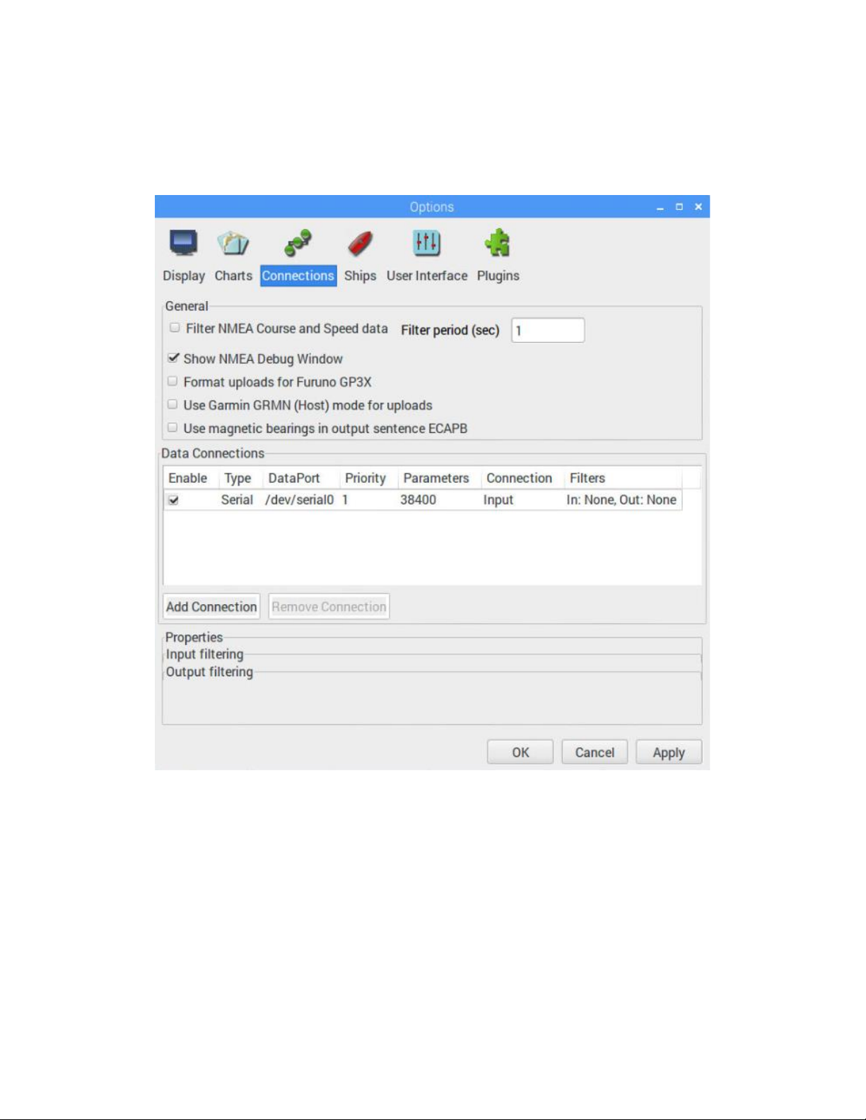
3.4 Configuration in OpenCPN............................................................................................................4
3.5 Connecting dAISy with other software.........................................................................................6
4Using dAISy ................................................................................................................................7
4.1 Interpreting the status LEDs .........................................................................................................7
4.2 Configuration and debug menu....................................................................................................8
5Using the breakout connections................................................................................................10
5.1 Serial 1 header ............................................................................................................................10
5.2 Serial 2 header ............................................................................................................................10
5.3 I2C header...................................................................................................................................11
5.4 Debug header..............................................................................................................................11
5.5 RF connectors..............................................................................................................................11
6Tips for good AIS reception .......................................................................................................12
6.1 Antenna.......................................................................................................................................12
6.2 Location, location, location.........................................................................................................12
6.3 Radio noise..................................................................................................................................13
7Troubleshooting .......................................................................................................................14
8Specifications ...........................................................................................................................15
9Source code and schematics......................................................................................................16
10 Contact.................................................................................................................................16

Wegmatt LLC
6356 138th Ave NE #212
Redmond, WA
United States of America
http://www.wegmatt.com
Designed and assembled in USA
2Disclaimer
dAISy HAT is a reliable, dual-channel AIS Receiver. However, under no circumstances it should be
solely relied on for collision avoidance or navigation. It’s the user’s responsibility to use the product
prudently. Neither Wegmatt LLC nor its dealers accept responsibility or liability to the product user or
their estate for any accident, loss, injury or damage whatsoever arising out of the use of this product.
3Configuring the Raspberry Pi for the dAISy HAT
The dAISy HAT communicates with the Raspberry Pi through the serial port broken out one the
Raspberry Pi’s expansion header. Out-of-the-box, the Raspberry Pi uses these pins for other purposes
like a serial terminal or Bluetooth.
Reconfiguring serial ports is straight forward with recent versions of Raspian (since ca. late 2016).
Configuration can be more complex with older version of Raspian, especially on the Raspberry 3. For
beginners, we recommend starting with a new image of Raspian.
3.1 Recent versions of Raspian
The uart_control shell script Ilker Temir is the easiest way to configure the serial port on a Raspberry Pi.
Open a terminal window on your Raspberry Pi and execute the following commands:
1. wget https://github.com/itemir/rpi_boat_utils/raw/master/uart_control/uart_control
2. chmod +x ./uart_control
3. sudo ./uart_control gpio
4. sudo reboot now
This will download the script, make it executable, run it to reconfigure the serial port for use with a HAT,
and rebooting the Raspberry Pi to make the new configuration active.
After completing the reboot, AIS data is available using the following parameters:
Serial port
/dev/serial0
Baud rate
38400
Data bits
8
Parity
None
Stop bits
1
Flow control
None

Use this information to configure OpenCPN or other programs. Keep in mind, that only one application
at a time can consume serial data.
You can verify the serial connection with a serial terminal program like for example screen. You may
have to install screen first by running:
sudo apt-get install screen
With screen installed, connect to the dAISy HAT with
screen /dev/serial0 38400
If the serial port is properly configured, pressing ESC will bring up the configuration and debug menu.
Pressing ESC again will return dAISy into receive mode. Exit screen by pressing CTRL-A, then K and then
Y.
3.2 Older versions of Raspian –Raspberry Pi, Pi 2 and Pi Zero
Older versions of Raspian require more manual steps to reconfigure serial ports.
If you have a Raspberry Pi, Raspberry Pi 2 or Raspberry Pi Zero, follow the steps outlined in the tutorial
for the Adafruit GPS HAT.
https://learn.adafruit.com/adafruit-ultimate-gps-hat-for-raspberry-pi/pi-setup
After completing the reboot, AIS data is available using the following parameters:
Serial port
/dev/ttyAMA0
Baud rate
38400
Data bits
8
Parity
None
Stop bits
1
Flow control
None
Use this information to configure OpenCPN or other programs. Keep in mind, that only one application
at a time can consume serial data.
You can verify the serial connection with a serial terminal program like for example screen. You may
have to install screen first by running:
sudo apt-get install screen
With screen installed, connect to the dAISy HAT with
screen /dev/ttyAMA0 38400
If the serial port is properly configured, pressing ESC will bring up the configuration and debug menu.
Pressing ESC again will return dAISy into receive mode. Exit screen by pressing CTRL-A, then K and then
Y.

3.3 Older versions of Raspian –Raspberry Pi 3
The Raspberry Pi 3 uses its serial port for the built-in Bluetooth module. Reconfiguring this with older
versions of Raspian can be quite complex and error prone. We strongly recommend using an up-to-date
version of Raspian and follow the steps outline in chapter 3.1 above instead.
If you still want to reconfigure an older version of Raspian, this blog post may help you:
https://thepihut.com/blogs/raspberry-pi-tutorials/raspberry-pi-gps-hat-and-python
After completing the reboot, AIS data is available using the following parameters:
Serial port
/dev/ttyAMA0
Baud rate
38400
Data bits
8
Parity
None
Stop bits
1
Flow control
None
Use this information to configure OpenCPN or other programs. Keep in mind, that only one application
at a time can consume serial data.
You can verify the serial connection with a serial terminal program like for example screen. You may
have to install screen first by running:
sudo apt-get install screen
With screen installed, connect to the dAISy HAT with
screen /dev/ttyAMA0 38400
If the serial port is properly configured, pressing ESC will bring up the configuration and debug menu.
Pressing ESC again will return dAISy into receive mode. Exit screen by pressing CTRL-A, then K and then
Y.
3.4 Configuration in OpenCPN
OpenCPN is a free chart plotter and navigation software. Among many other things, OpenCPN supports
input from AIS receivers to display the position of ships on its charts.
You can learn more about OpenCPN on http://opencpn.org
There are several tutorials on the web on running OpenCPN on a Raspberry Pi. The consensus is, that
you should only attempt this on a Raspberry Pi 3 or 4 with an up-to-date version of Raspian. The official
instructions can be found here:
https://opencpn.org/wiki/dokuwiki/doku.php?id=opencpn:opencpn_user_manual:getting_started:open
cpn_installation:raspberrypi_rpi2
Alternatively, users have reported good results by following this procedure:
http://www.agurney.com/raspberry-pi/pi-chart

Once OpenCPN is running on the Raspberry Pi, configure it for the dAISy HAT. Go to the Options dialog,
select the Connections icon and add a new connection. Set Properties to Serial. Enter or select the
Dataport under which dAISy presents itself (see chapters above to determine the correct port). Set
Baudrate to 38400. Leave everything else as preset by OpenCPN.
Configuration of a serial connection for dAISy in OpenCPN

3.5 Connecting dAISy with other software
dAISy presents itself to computers as a serial port. See the configuration chapters above about
installation to learn how to determine the serial port.
The serial communication parameters of dAISy are:
Baud rate
38400
Data bits
8
Parity
None
Stop bits
1
Flow control
None
Depending on the software dAISy is used with, some or all parameters must be configured. For details,
please refer to the instruction manual of the respective application.

4Using dAISy
Using dAISy is as simple as connecting it with an antenna and a PC and powering up your AIS capable
application of choice. When plugged in, dAISy automatically starts to listen for AIS transmissions.
4.1 Interpreting the status LEDs
The dAISy HAT has two two-color status LED, giving us some indication about how it’s feeling. Each LED
represents one of the two AIS channels.
Short GREEN flash every 5 seconds
dAISy is well and alive and in receive mode.
While in receive mode, the mode dAISy starts in when powered up, it will very briefly blink green every 5
seconds to indicate that everything is ok.
Long GREEN flash
Yay! dAISy received a valid AIS packet.
For every packet received and passing all error checks, the LED will turn green for ¼ second. At the same
time, dAISy will send the received message to the Raspberry Pi.
Long RED flash
dAISy received an invalid packet.
dAISy caught the start of a package, but the received data did not pass other sanity checks like encoding
standard or checksum. It might be a ship just out of range, interference from another radio source, or
just random noise.
Don’t panic, you will see a lot of red even under optimal conditions.
RED turned on permanently
dAISy failed to initialize the radio IC.
Shut down the Raspberry Pi and remove power. Plug it in again and see if this resolves the problem. If
the condition persists, there might a hardware issue with your device. Please contact us.
Fast regular blinking RED
dAISy encountered an unexpected system error.
Shut down the Raspberry Pi and remove power. Plug it in again and see if this resolves the problem. If
the condition persists, there might a hardware issue with your device. Please contact us.
No LED activity
Most likely, dAISy is not in receive mode because you are using the configuration menu.
Connect to dAISy with a serial terminal and press ESC. A message should tell you that it entered AIS
receive mode and the green LED should start to blink every 5 seconds.

Another possibility is, that dAISy failed to boot or crashed.
In this case, shut down the Raspberry Pi and remove power. Plug it in again and see if this resolves the
problem. If the condition persists, there might a hardware issue with your device. Please contact me.
4.2 Configuration and debug menu
When connecting to dAISy with a serial terminal (e.g. screen), pressing ESC will bring up a menu with a
few configuration and debug options.
The most commonly used options are:
0-3: Controls the Serial 2 header on the HAT. 1 enables the port at 4800 baud, 2 is for 9600, and 3 is for
38400 baud. 0 turns Serial 2 off.
S: Selects the function of Serial 2. Serial 2 can either:
-Output AIS messages, for example to a Bluetooth module, RS-422/NMEA0183 adapter, or a data
logger.
-Act as an input for NMEA messages, for example from a GPS module. All data received through
Serial 2 will be forwarded to the Raspberry Pi.
D: Toggles debug messages, when in receive mode signal strength as well as information about invalid
packets will be displayed. It’s normal to receive a lot of broken packages, as there always will be radio
noise and ships just barely out of reach. With some experience, you can use the debug messages to
analyze and improve reception issues.

#: Save current settings (serial, C, L, R and D) as startup defaults. This is particularly useful when you
want to persist the settings for the auxiliary serial output.
ESC: Resume receiving AIS messages.
Other options:
N: Keep pressed to get an idea of the current noise level. -120 to -100 dBm is normal. dAISy will only be
able to receive valid packets roughly 15 dBm above that level, consistent reception 25+ dBm above
noise.
V: If valid packages were received, this gives a summary of the signal strength at which they arrived
(min, max, average).
T: Enter test mode. In this mode, dAISy outputs a test message every 5 seconds. You can enter your own
message or have it output a preprogrammed AIS message. This mode is useful when you want to test
dAISy but don’t have AIS reception at your current location. You can exit test mode by pressing ESC or
power-cycling dAISy.
C: Configure receiving channel. The dAISy HAT has two radios, which by default are configured to listen
on channel A and B respectively. For experimental purposes, the channel assignment of the radios can
be changed to A/A, B/B, A/B or B/A. The recommended setting is A/B.
R: Turn RSSI Detect on or off. When RSSI detect is on, dAISy will ignore signals that are too weak for
reliable communication. This may increase the number of local messages received, but it will also reduce
the maximum range. The recommended setting is OFF.
L: Turn Low Power Mode on or off: In low power mode, the CPU of dAISy will be powered down when
idle. This will reduce power consumption by about 10-15%. As this is insignificant in typical applications,
the recommended setting is OFF.
B: Enter boot loader mode for firmware updates. dAISy only exits this mode through power-cycling or
after completing firmware upgrade. Check our website for the latest firmware updates.

5Using the breakout connections
The dAISy HAT AIS Receiver breaks out several interfaces as unpopulated footprints for 0.1” headers.
All digital interfaces are 3.3V only.
5.1 Serial 1 header
The header Serial 1 exposes the primary serial
interface of the dAISy AIS Receiver. It is connected
in parallel with the serial interface of the Raspberry
Pi, and offers the same data and functionality.
Serial 1 is always active and runs at 38400 baud. It
can be used to run the dAISy HAT standalone,
without being connected to a Raspberry Pi.
When connected to a Raspberry Pi, Serial 1 should
only be used to receive the same data as the
Raspberry Pi. Do not send data through the RX pin
while the HAT is connected to a Raspberry Pi.
The 5V pad is connected to the 5V power rail of the
Raspberry Pi. When the dAISy HAT is not connected
to the Raspberry Pi, the 5V pad can be used to power the AIS Receiver. When running standalone, the
dAISy HAT will draw a maximum current of 40mA in receive mode.
dAISy Serial 1
dAISy MCU
Raspberry Pi
Comment
5V
5V to 3.3V LDO
Pin 2, 5V
5V power rail of Raspberry Pi and HAT. Can
be used to power HAT standalone.
GND
GND
GND
Connected to the GND plane of the HAT
TX
Serial 1 TXD
Pin 10, UART0_RXD
Serial data out, 3.3V signal level, 38400 bps
RX
Serial 1 RXD
Pin 8, UART0_TXD
Serial data in, 3.3V signal level, 38400 bps.
Don’t use when HAT is connected to
Raspberry Pi.
IO
GPIO
-
Currently not in use.
5.2 Serial 2 header
The header Serial 2 exposes the secondary serial interface of the dAISy AIS Receiver. This serial port is
controlled by dAISy’s MCU and not connected to the Raspberry Pi.
Speed and function of Serial 2 are configured in the debug menu. It can operate as secondary output or
as NMEA input. The pinout is compatible with the Adafruit Ultimate GPS module.
The 5V pad is connected to the 5V power rail of the Raspberry Pi. When the dAISy HAT is not connected
to a Raspberry Pi, the 5V pad can be used to power the AIS Receiver. When running standalone, the
dAISy HAT will draw a maximum current of 40mA in receive mode.

dAISy Serial 2
dAISy MCU
Raspberry Pi
Comment
5V
5V to 3.3V LDO
Pin 2, 5V
5V power rail of Raspberry Pi and HAT. Can
be used to power HAT standalone.
GND
GND
GND
Connected to GND plane of dAISy HAT
TX
Serial 2 TXD
-
Serial data out, 3.3V signal level,
configurable speed.
RX
Serial 2 RXD
-
Serial data in, 3.3V signal level, configurable
speed.
IO
GPIO
-
Currently not in use.
5.3 I2C header
This header breaks out the I2C interface of the Raspberry Pi. This allows applications running on
Raspberry Pi to communicate with I2C sensors. For example, OpenPlotter supports temperature,
pressure, humidity and light sensors.
The I2C interface is independent of the AIS Receiver and the pads are directly connected to the
Raspberry Pi expansion header. For more information about the I2C interface, refer to the
documentation of the Raspberry Pi.
dAISy I2C
Raspberry Pi
Comment
3V3
Pin 1, 3V3
3.3V power from Raspberry Pi, 50mA max
current
SDA
Pin 3, SDA1 / GPIO2
I2C data, 3.3V signal level
SCL
Pin 5, SCL1 / GPIO3
I2C clock, 3.3V signal level
GND
GND
Connected to GND plane of dAISy HAT
5.4 Debug header
The debug header breaks out the debug and programming interface of the MCU controlling the AIS
receiver. The MCU is a Texas Instrument MSP430F5232.
The debug header also gives access to the 3.3V power rail of the AIS receiver, which can be used to
power peripherals. Maximum current available is 150mA. Recommended current for continuous
operation is 50mA. Back-powering the AIS receiver through the 3.3V pad is possible but may degrade RF
performance.
dAISy Debug
dAISy MCU
Raspberry Pi
Comment
GND
GND
GND
Connected to GND plane of dAISy HAT
TST
TEST / SBWTCK
-
TI SBW programming interface
RST
RST / SBWTDIO
-
TI SBW programming interface, reset
3V3
3V3
-
Connected to 3.3V rail of dAISy HAT. 150mA
max current, 50mA continuous.
5.5 RF connectors
The edge-mount antenna connector of the dAISy HAT is female SMA, standard polarity. There is also an
unpopulated footprint for a surface mount vertical MMCX connector, for example Molex 73415-2061.

6Tips for good AIS reception
dAISy is not the most sensitive AIS receiver out there. But you we can help it to excel with some basic
measures.
6.1 Antenna
If everything else is optimal, almost any antenna tuned to the VHF band will do. I used a simple wire cut
to length for my first prototypes. However, a good antenna will greatly improve results.
AIS messages are broadcast on two channels around 162 MHz, which is in the maritime VHF band. This
means that any antenna sold as “marine VHF antenna” will be a good start.
The short VHF “rubber duck” antennas are cheap and will work at short distance. As long as you check
whether 162 MHz is inside the supported frequency range, you can even ignore the “marine” and save a
few bucks. However, the more broadband the antenna, the worse the reception quality.
A step up are VHF whip antennas. These are steel rods about 1 meter (3.5ft) long. While bulky, these
don’t cost much more than the “rubber duck” but provide superior results. Personally, I use the TRAM
1600-HC which cost around US $40.
There are many more options, which I did not explore myself yet. This article gives a great overview of
the topic: http://sdrformariners.blogspot.com/2013/08/ais-antenna-shootout.html
Note: dAISy uses a BNC connector for its antenna input. Depending on the antenna
you buy (or build), you might need an adapter. In the U.S. I can recommend
coaxrf.com for a good selection, reasonable prices and fast shipping.
The AIS antenna should be separated as far as possible from the voice VHF antenna to avoid
unnecessary interference. The best separation is achieved by vertically separating the antennas or at
least mounting them on opposite sides of a vessel.
To avoid damaging dAISy’s receiver, the antenna should be mounted at least 3 meters away from, or at
least out of the transmitting beam, of high-power transmitters such as radars or other VHF antenna
installations.
6.2 Location, location, location
Good AIS reception requires line of sight.
A few building and trees between you and your targets aren’t ideal, but you will still be able to catch a
few messages. Hills and mountains however are almost certain showstoppers. A clear view of the water
and your targets is ideal.
In my experience the most important factor is the height of the antenna above sea-level (or lake-, river-,
wherever-level the ships are). Sitting at the beach or on the deck of a boat will work. Mounting the
antenna on the mast of your boat, or standing on the observation deck of a cruise ship is better. A hill
overlooking the harbor is great. Climbing that 2000m mountain that towers over the coast is AIS heaven.

In a nutshell: The farther you can see, the better.
6.3 Radio noise
The main weakness of dAISy, and probably most low-cost and SDR-based AIS receivers, is susceptibility
to radio noise. The effect of noise is reduced range and few successfully received packets.
Unfortunately, there’s not much we can do except finding a spot that’s less impacted by noise. Outdoors
is better than indoors (computers, power-supplies, wireless networks, ...). Country-side is better than
down-town (taxi radios).
dAISy has an integrated 12 MHz wide bandpass filter to reduce the impact of radio noise outside the 162
MHz target frequency. However, to keep cost and size down, the integrated filter is rather simple. A very
narrow-band antenna or an external bandpass filter can improve reception. Please report back any
results if you go down this route.

7Troubleshooting
Problem
Solution
No activity of the status LEDs
Verify that the device is not in the configuration
menu.
Device in reception mode, but not valid AIS
messages received (no ¼ second green flashes)
Verify the antenna connection and location.
Good AIS reception requires line-of-sight, verify
your setup from a location that is certain to have
traffic, e.g. near a harbor.
Device indicates valid AIS messages (¼ second
green flashes), but no messages received on the
Raspberry Pi.
Verify that the serial port shows up, if not verify
the hardware configuration. Verify the serial
configuration of your software. Verify the serial
communication with a program like screen.
Software receives positions, but fewer than
expected and/or with worse range than
expected.
Verify the antenna connection and location.
Good AIS reception requires line-of-sight. Move
the antenna away from sources of electrical
noise.
After some time, dAISy indicates a device error
(fast blinking red LED)
This should not occur with the dAISy HAT. Power
cycle the Raspberry Pi to resolve the issue.
If a problem persists, don’t hesitate to contact us.

8Specifications
Power
Power input ports
Raspberry Pi Header (RPi), Serial 1 & 2, Debug
header
Input voltage RPi / Serial 1 / Serial 2
5V
Input voltage Debug
3.3V
Input current RPi / Serial 1 / Serial 2 / Debug
< 35 mA
Power output ports
Serial 1, Serial 2, Debug header
Output voltage Serial 1 / Serial 2
5V
Output voltage Debug
3.3V
Maximum output current Serial 1 / Serial 2
Limited by external 5V supply
Maximum output current Debug
150mA
Radio
Independent receivers
2
Frequency bands
161.975MHz and 162.025MHz
AIS channels
A/B, A/A, B/B, B/A configurable
Bandpass filter
SAW 156.3 - 162.025MHz pass band
RF connector
SMA
Input impedance
50Ω
Data I/O
AIS message encoding
NMEA 0183 (!AIVDM)
Supported AIS message types
1-27
Serial speed RPi / Serial 1
38400 Baud fixed
Serial speed Serial 2
4800, 9600, 38400 Baud configurable
Serial protocol
8 data bits, no parity, 1 stop bit (8N1)
Serial mode RPi / Serial 1
NMEA out fixed
Serial mode Serial 2
NMEA out, NMEA in configurable
Serial signal voltage RPi
3.3V
Serial signal voltage Serial 1 / Serial 2
3.3V (5V tolerant)
Dimensions
Circuit board without connectors
65mm x 56mm
Circuit board with connectors
65mm x 66mm x 14mm (6mm w/o RPi conn)
Circuit board mounting holes
4x Size: 2.75mm (M2.5) Distance: 58mm x 49mm
See also: https://github.com/raspberrypi/hats/blob/master/hat-board-mechanical.pdf
Weight
Product
18g
w/o 40-pin Raspberry Pi header
14g

9Source code and schematics
Currently dAISy is only partially open source.
The core of dAISy, how the Si4362 radio IC is programmed to receive AIS, is available on Github. While
the project does not include all the functionality of dAISy as sold, I do backport any bug fixes that are
relevant to the task of receiving AIS. https://github.com/astuder/dAISy
There’s also a long thread on 43oh that documents the journey of dAISy from its humble beginnings.
http://forum.43oh.com/topic/4833-potm-daisy-a-simple-ais-receiver/
If you want to mess with the real code, brick your device with custom firmware or even build your own
dAISy from scratch, please contact me.
10 Contact
You can also contact the designer of dAISy via GitHub, 43oh or Tindie.
http://www.wegmatt.com
Wegmatt LLC
6356 138th Ave NE, #212
Redmond, WA 98052
United States of America
Other manuals for dAISy HAT
2
Table of contents
Other Wegmatt Receiver manuals