3
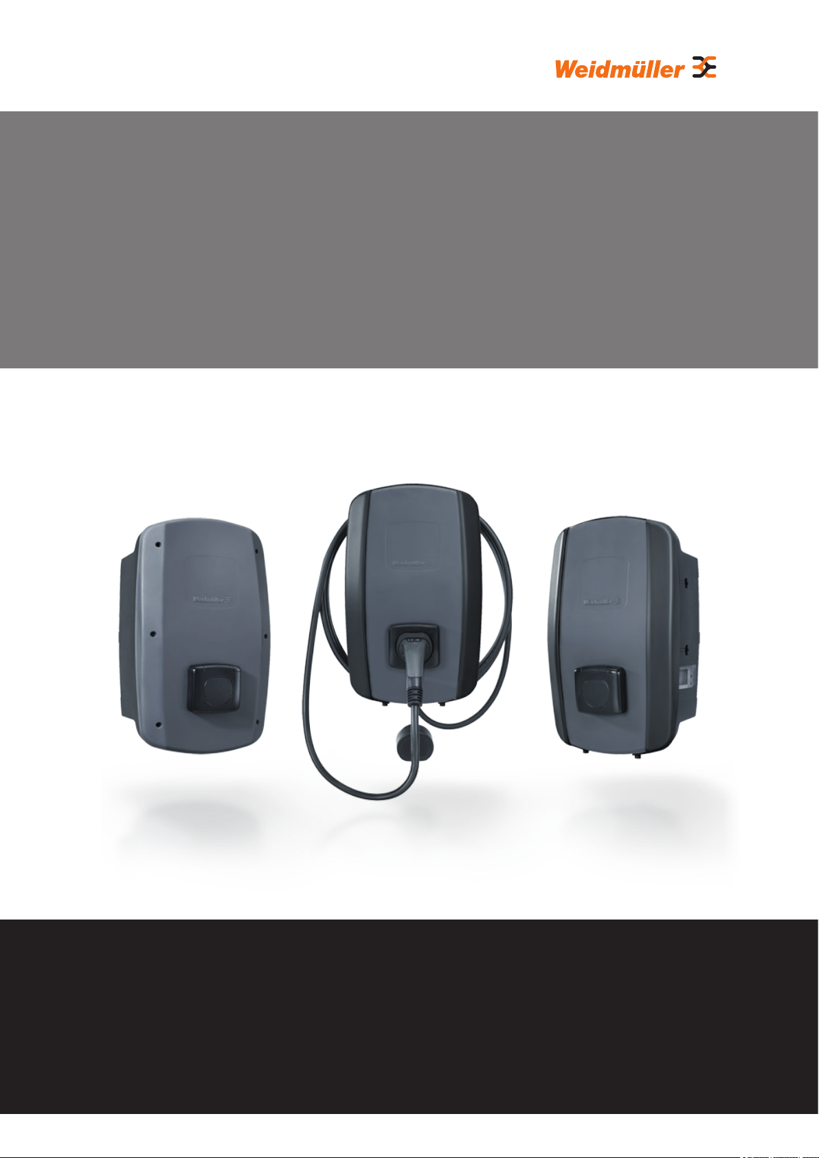
Operating instructions – AC SMART
Manufacturer
Weidmüller Interface GmbH & Co. KG
Klingenbergstraße 26
32758 Detmold, Germany
T +49 (0)5231 14-0
F +49 (0)5231 14-292083
www.weidmüller.com
Document no. 2984390000
Revision: 03/07.2023
Contents
1 About these instructions 5
1.1 Applicable documents: 5
1.2 Illustrations and symbols 5
2 For your safety 6
2.1 Intended use 6
2.2 Personnel 6
2.3 Safety notes 6
2.4 Productmodications 7
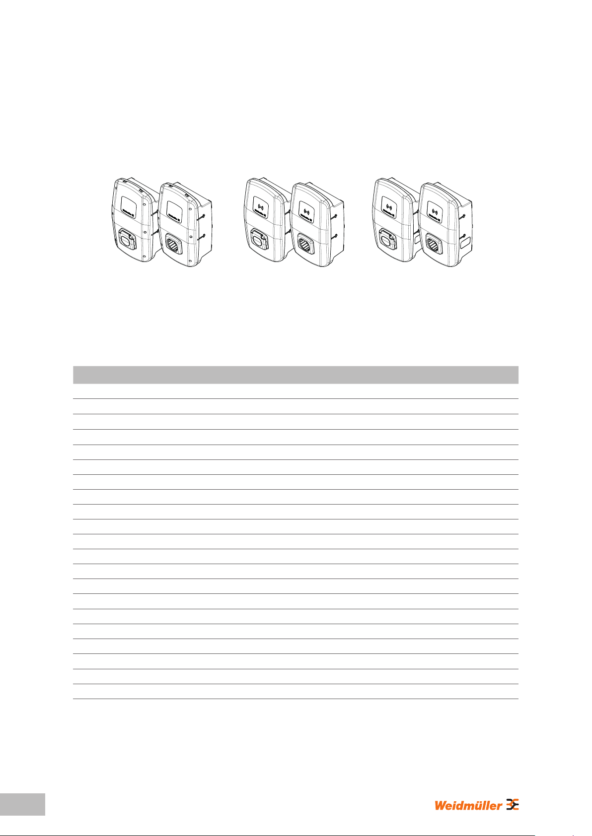
3 Product description 8
3.1 AC SMART product family 8
3.2 Type plate 9
3.3 Product components 10
3.4 Connections and electronic components 11
3.5 Status LED and acoustic signals 13
4 Product functions 14
4.1 Network capability 14
4.2 Communication capability 14
4.3 Operating software web server and
AC SMART app 15
4.4 Charging the vehicle 16
4.5 Status information and error display 16
4.6 Download and delete charging data 16
4.7 Monitor charging process 17
4.8 Maximum charging current 17
4.9 Maximum asymmetrical phase current 17
4.10 LED inactivity 17
4.11 Digital inputs 18
4.12 Load/charge management 18
4.13 PV optimised charging 20
4.14 User authentication 22
5 Unpacking and checking
the scope of delivery 23
5.1 Unpacking the delivery 23
5.2 Checking the scope of delivery 23
6 Storing the EV charging box 25
7 Preparing for installation 26
7.1 Selecting the installation site 26
7.2 Ordering installation 26
7.3 Tools required 26
7.4 Check list before installation 27
8 Planning the installation 28
8.1 Installation Guidance 28
8.2 Network systems 29
8.3 Check list for initial commissioning 30
9 Networking and conguring
the EV charging box 31
9.1 Connecting the EV charging box
with the local network 31
9.2 Assigning the network settings
and IP address 32
9.3 ConguringtheEVchargingbox
in the web server 33
9.4 Connecting the EV charging box to an
external device (Modbus) 43
9.5 Connecting the EV charging box to an
external device (digital input) 44
9.6 Starting Bluetooth coupling mode 45
9.7 Coupling the EV charging box with the
AC SMART app 45
9.8 ConguringtheEVchargingboxvia
AC SMART app 46