Weidmüller ACT20X User manual

ACT20X
User Manual

Revision History
Version Date Change
1.0 First Edition
Contact Address
Weidmüller Interface GmbH & Co. KG
PO Box 3030
32720 Detmold
Klingenbergstrasse 16
32758 Detmold
Germany
Phone +49 (0) 5231 14-0
Fax +49 (0) 5231 14-2083
E-Mail [email protected]
Internet www.weidmueller.com

1066540000/00/02.09 3
Contents
Revision History ...............................................................................................................................................2
Contact Address...............................................................................................................................................2
Contents.............................................................................................................................3
1. Approvals...............................................................................................................5
1.1 CE........................................................................................................................................................5
1.2 EMC.....................................................................................................................................................5
1.3 ATEX...................................................................................................................................................5
1.4 IECEx..................................................................................................................................................5
1.5 cFMus.................................................................................................................................................5
1.6 UL........................................................................................................................................................5
1.7 GOST ..................................................................................................................................................5
1.8 DNV.....................................................................................................................................................5
2. Warranty Statement ..............................................................................................6
2.1 36 Months Warranty..........................................................................................................................6
3. Safety .....................................................................................................................7
3.1 Approved Use....................................................................................................................................7
3.2 Qualified Personnel...........................................................................................................................7
3.3 Accuracy of the Technical Documentation ....................................................................................7
3.4 Liability...............................................................................................................................................7
3.5 Definitions..........................................................................................................................................7
3.6 Symbol Identification........................................................................................................................7
3.7 Electrical Precautions.......................................................................................................................8
3.8 General Instructions .........................................................................................................................8
4. Introduction...........................................................................................................9
4.1 Product Description..........................................................................................................................9
4.1.1 Family ACT20X....................................................................................................................9
4.1.2 General Description ...........................................................................................................10
4.1.3 The Six Basic Module Types in Detail ...............................................................................10
5. Installation...........................................................................................................12
5.1 General.............................................................................................................................................12

4 1066540000/00/02.09
5.1.1 Environment.......................................................................................................................12
5.2 Unpacking........................................................................................................................................12
5.3 Mounting ..........................................................................................................................................13
5.4 Marking.............................................................................................................................................13
5.5 Electrical Connections ...................................................................................................................14
5.5.1 EMI Protection ...................................................................................................................14
5.6 Calibration and Adjustment ...........................................................................................................14
5.7 Release Lever..................................................................................................................................14
5.8 Encoding..........................................................................................................................................15
5.9 Configuration...................................................................................................................................15
6. Operation.............................................................................................................17
6.1 Normal Operation............................................................................................................................17
6.2 Warm-Up ..........................................................................................................................................17
6.3 Cleaning ...........................................................................................................................................17
7. Product Installation / Operation.........................................................................18
7.1 ACT20X-HDI-SDO (NAMUR Pulse Isolator) ..................................................................................18
7.1.1 Description .........................................................................................................................18
7.1.2 Status/Alarm LEDs.............................................................................................................18
7.1.3 Electrical Connections .......................................................................................................19
7.1.4 Function Description ..........................................................................................................20
7.1.5 Specifications.....................................................................................................................20
7.2 ACT20X-HTI-SAO (Temperature and mA Converter)...................................................................25
7.2.1 Description .........................................................................................................................25
7.2.2 Status/Alarm LEDs.............................................................................................................25
7.2.3 Electrical Connections .......................................................................................................26
7.2.4 Specifications.....................................................................................................................27
7.3 ACT20X-SDI-HDO (Solenoid/Alarm Driver)...................................................................................35
7.3.1 Description .........................................................................................................................35
7.3.2 Status/Alarm LEDs.............................................................................................................35
7.3.3 Electrical Connections .......................................................................................................36
7.3.4 Specifications.....................................................................................................................37
7.4 ACT20X-HUI-SAO (Universal Converter) ......................................................................................43
7.4.1 Description .........................................................................................................................43
7.4.2 Status/Alarm LEDs.............................................................................................................43
7.4.3 Electrical Connections .......................................................................................................44
7.4.4 Specifications.....................................................................................................................45
Appendix..........................................................................................................................54

1066540000/00/02.09 5
1. Approvals
1.1 CE
These products fulfill the guidelines issued by the
European Union and are therefore entitled to carry
the CE mark.
1.2 EMC
In accordance with:
- EN 61326
1.3 ATEX
In accordance with:
- EN 60079-0, -11, -15 , -26
- EN 61241-0, -11
ATEX marking:
II 3 G Ex nA nC IIC T4
II (1) G [Ex ia] IIC/IIB/IIA
II (1) D [Ex iaD]
1.4 IECEx
In accordance with:
- IEC 60079-15: 2005
- IEC 60079-11: 2006
- IEC 60079-0: 2007
- IEC 60079-26: 2006
- IEC 61241-0: 2004
- IEC 61241-11: 2005
IECEx marking:
Ex nA nC IIC T4 Gc
[Ex ia Ga] IIC/IIB/IIA
[Ex ia Da] IIIC
1.5 cFMus
In accordance with:
Canada
- E60079-0
- E60079-11
- E60079-15
- CSA 22.2-157
- CSA 22.2-213
USA
- UL60079-0
- UL60079-11
- UL60079-15
- FM3600
- FM3610
- FM3611
- FM3810
cFMus marking:
Install in CL I DIV2 GP A-D T4
Provides IS circuits to CL I-III DIV 1/2 GP A-G or
CL I Zn2 AEx/Ex nA nC [ia] IIC T4.
1.6 UL
In accordance with:
- UL 61010-1
1.7 GOST
GOST approval is pending.
1.8 DNV
Marine approval is pending.

6 1066540000/00/02.09
2. Warranty Statement
2.1 36 Months Warranty
Weidmüller gives a 36 months warranty on the
product in accordance with the warranty terms as
described in the general business conditions of
the Weidmüller company which has sold the
products to you.
Weidmüller guarantees that defects which have
already existed at the time when the risk passed
will be repaired by Weidmüller free of charge or
Weidmüller will provide a new, functionally
equivalent product to replace the defective one.
The warranty referred to above covers Weidmüller
products. Unless otherwise expressly stated in
this catalogue/product description, Weidmüller
gives no warranty or guarantee as to the
interoperability in specific systems or the fitness
for any particular purpose. To the extent permitted
by law, any claims for damages and
reimbursement of expenses, based on whatever
legal reason, including contract or tort, shall be
excluded.
Unless otherwise expressly stated in this
warranty, the general business conditions and the
expressive liability commitments therein of the
respective Weidmüller company which has sold
the products to you are applicable.

1066540000/00/02.09 7
3. Safety
3.1 Approved Use
This product is intended for use in applications as
described in the operating instructions only.
Any other utilization is not permitted and can lead
to accidents or destruction of the device.
Using the device in non-approved applications will
immediately void all guarantee and warranty
claims on the part of the operator against the
manufacturer.
3.2 Qualified Personnel
These operating instructions are intended for
trained and qualified personnel that is familiar with
the valid regulations and standards relevant to the
field of application.
3.3 Accuracy of the Technical
Documentation
These operating instruction were written with due
care and attention.
However, unless otherwise required by law, we do
not guarantee that the data, images and drawings
are accurate or complete nor do we accept liability
for their contents.
Weidmüller’s general business conditions apply in
their respective valid form. They are subject to
alteration without notice.
3.4 Liability
To the extent that instructions in this manual are
not strictly observed, the customer cannot
advance a demand against Weidmüller that would
otherwise exist according to the concluded sales
agreement.
3.5 Definitions
•Hazardous voltages have been defined as the
ranges: 75…1,500 V DC and 50…1,000 V AC.
•Technicians are qualified persons trained to
mount, operate and troubleshoot technically
correct and in accordance with safety
regulations.
•Operators, being familiar with the contents of
this manual, adjust and operate the knobs or
potentiometers during normal operation.
3.6 Symbol Identification
DANGER
Indicates an imminently hazardous
situation which, if not avoided, will
result in death or serious injury.
WARNING
Indicates a potentially hazardous
situation which, if not avoided, could
result in death or serious injury.
CAUTION
Indicates a potentially hazardous
situation which, if not avoided, may
result in minor or moderate injury.
NOTICE
Indicates a situation that may result in material
damage.
The CE mark proves the compliance of
the module with the essential
requirements of the directives.
Ex modules have been approved
according to the ATEX directive for use
in connection with installations in
explosive areas.
This symbol is combined with one of
the signal words DANGER, WARNING
or CAUTION to indicate a hazardous
situation.

8 1066540000/00/02.09
The double insulation symbol shows
that the device is protected by double
or
reinforced insulation..
3.7 Electrical Precautions
WARNING
High voltage!
•Before removing or mounting the unit,
turn off power supply.
Follow ESD installation regulations,
including EMI precautions.
3.8 General Instructions
•Read and follow all instructions in this manual.
•Inform yourself about hazards which can be
caused by the product.
•Observe the safety and accident prevention
regulations.
•Regularly check that all measures to prevent
accidents are being complied with.
•Only operate the product if it is in perfect
technical condition, according to its intended
use, in awareness of safety and risks and in
adherence to the instructions in this manual.
•Keep this manual and all other applicable
documents complete, legible and accessible to
personnel at all times.
•Refrain from any procedures and actions that
would expose personnel or third parties to any
risk.

1066540000/00/02.09 9
4. Introduction
4.1 Product Description
4.1.1 Family ACT20X
Order No. Type Description Function
8965340000 ACT20X-HDI-SDO-RNO-S NAMUR isolator - relay NO NAMUR in (from Ex)
to relay out
8965350000 ACT20X-HDI-SDO-RNC-S NAMUR isolator - relay NC NAMUR in (from Ex)
to relay out
8965360000 ACT20X-HDI-SDO-S NAMUR isolator NAMUR in (from Ex)
to digital out
8965370000 ACT20X-2HDI-2SDO-RNO-S 2 Ch. NAMUR isolator -
relay NO
2x NAMUR in (from Ex)
to 2x relays out
8965380000 ACT20X-2HDI-2SDO-RNC-S 2 Ch. NAMUR isolator -
relay NC
2x NAMUR in (from Ex)
to 2x relays out
8965390000 ACT20X-2HDI-2SDO-S 2 Ch. NAMUR isolator 2x NAMUR in (from Ex)
to 2x digital out
8965400000 ACT20X-SDI-HDO-L-S Solenoid / alarm driver,
L = low current max. 35 mA
digital in to safe digital out
(to Ex IIC)
8965410000 ACT20X-SDI-HDO-H-S Solenoid / alarm driver,
H = high current max. 60 mA
digital in to safe digital out
(to Ex IIB)
8965420000 ACT20X-2SDI-2HDO-S 2 Ch. Solenoid / alarm driver,
low current max. 35 mA
2x digital in to 2x safe digital out
(to Ex)
8965430000 ACT20X-HAI-SAO-S HART-transparent
repeater
mA in (from Ex) to mA out
with HART transparency
8965440000 ACT20X-2HAI-2SAO-S 2 Ch. HART-transparent
repeater
2x mA in (from Ex) to 2x mA out
with HART transparency
8965450000 ACT20X-SAI-HAO-S HART-transparent driver mA in to mA out (to Ex)
with HART transparency
8965460000 ACT20X-2SAI-2HAO-S 2 Ch. HART-transparent
driver
2x mA in to 2x mA out (to Ex)
with HART transparency
8965470000 ACT20X-HTI-SAO-S Temperature / mA converter temperature in (from Ex)
to mA out
8965480000 ACT20X-2HTI-2SAO-S 2 Ch. temperature / mA
Converter
2x temperature in (from Ex)
to 2x mA out
8965490000 ACT20X-HUI-SAO-S Universal converter universal analog in (from Ex)
to analog (V / mA) + trip relay
out
Table 4-1: Family ACT20X

10 1066540000/00/02.09
4.1.2 General Description
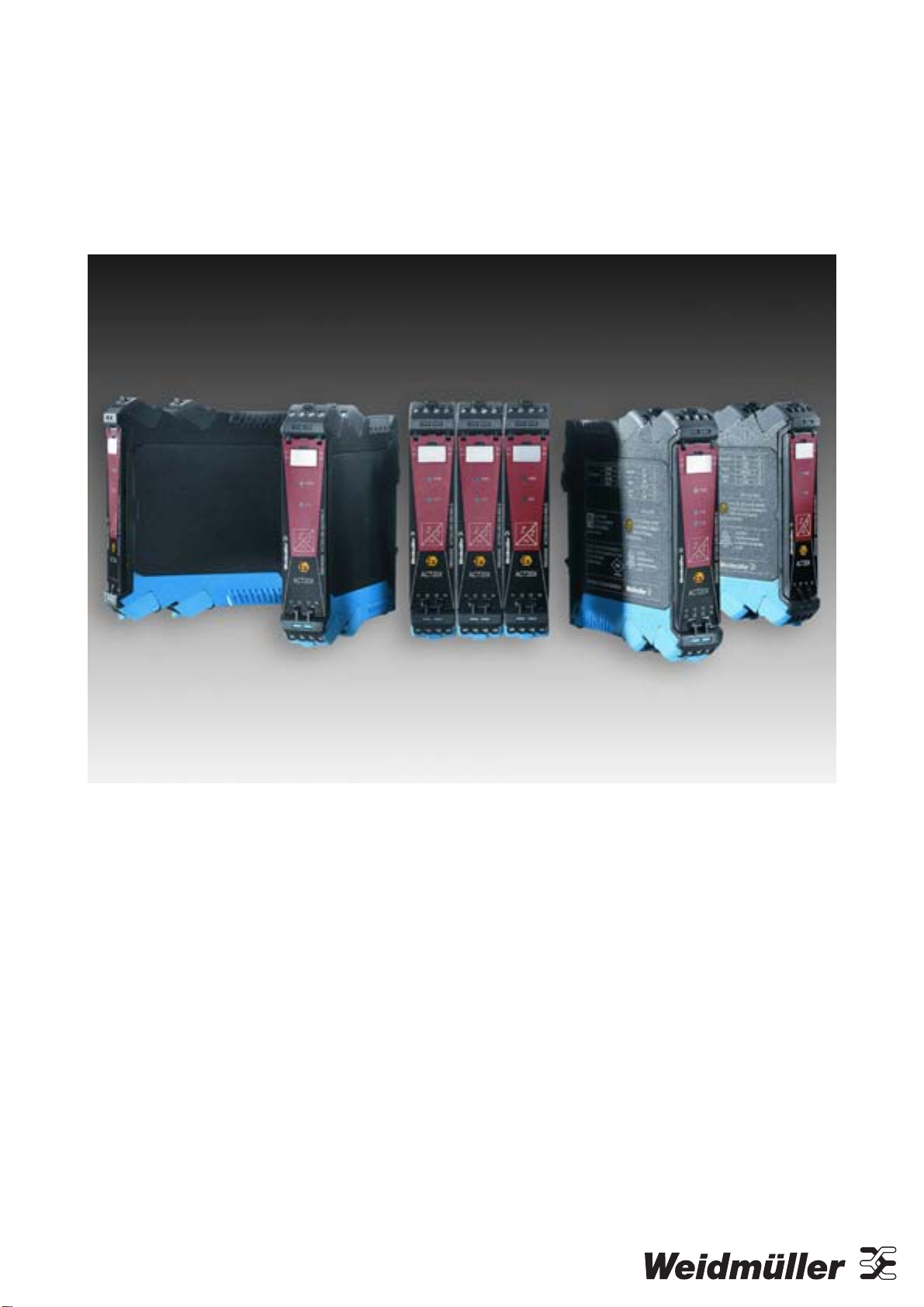
Weidmüller’s ACT20X – new signal converters for
hazardous areas: Universal family of products
covers the entire field of hazardous area
applications with six different basic functions.
With the introduction of its ACT20X modules
Weidmüller is offering a completely new family of
signal converters for hazardous area applications.
With just 11 mm per channel these compactly
designed modules require very little space in the
electrical cabinet. All ACT20X converters can be
configured via a PC utilizing the software ‘WI-
Manager’. This software is based on vendor-neutral
FDT/DTM technology. The innovative modules are
designed to be installed in safe or hazardous areas
of Zone 2. The ACT20X family includes digital and
analogue intrinsically safe converters that both
isolate and convert signals from as well as into
hazardous areas. The innovative signal converters
process 2-wire HART, NAMUR, RTD, thermocouple
or DC signals as well as digital signals with electrical
connection to hazardous area Zone 0. All modules
have 3-way separation and are optionally available
with dual channel functionality. With high levels of
insulation resistance, accuracy and thermal stability
ACT20X modules provide a pure, disturbance free
signal at all times. A relay-based error monitoring
facility simplifies servicing. ACT20X modules can be
utilized in temperatures from –20 °C to +60 °C
without restrictions. They have all relevant
international approvals such as ATEX, IECEx,
GOST, FM – in other words, the modules are
predestined for use in applications all over the world.
Weidmüller specifically developed its ACT20X family
of products for process automation tasks in
hazardous and non-hazardous area applications.
The 16 different variants condition all conventional
input signals (2-wire HART, NAMUR, RTD,
thermocouple and DC signals) from sources within
hazardous area Zone 0 as equally as digital and
analogue signals into hazardous areas to control
field devices. To ensure rapid error identification the
integrated relay output supplies an error message
should an error occur – a facility that increases plant
availability.
Utilizing the ‘WI-Manager’ configuration software
based on FDT technology (Field Device Tool) makes
it possible to adapt all ACT20X products via a PC to
meet different process application requirements. For
this purpose Weidmüller provides the Device Type
Manager (DTM), which can be executed in any FDT-
based frame application. As well as fast and error-
free parameterization of individual devices DTMs
make it possible to evaluate measurement and
diagnostic data. In addition, it is possible to
unambiguously identify a connected device via DTM.
ACT20X modules are equipped with a cleverly
designed connection technology that supports
simple, coded mating. The integrated release lever
ensures the connection can be disconnected without
damage when servicing is required. Devices from
the ACT20X family have been designed to operate
in an ambient temperature range of –20 °C to
+60 °C – in other words in practically all fields of
industry. The hinged and transparent front plate can
easily be opened upwards. It has been designed for
simple accommodation of device markers.
Products from the ACT20X assortment are designed
to be installed in Zone 2 / Div. 2 or in non-hazardous
areas; international approvals such as ATEX,
ICEEx, GOST and FM (Class 1, Division 1 and 2)
allow processing of signals from Zone 0 / Div. 1. Put
succinctly, the modules are suitable for use in
applications across the globe.
4.1.3 The Six Basic Module Types in
Detail
NAMUR Isolator
The pulse isolator ACT20X-HDI-SDO is a special
signal isolator/converter for NAMUR sensor signals
from within Ex Zone 0. Transistor or relay outputs
are available on the output side. A dual-channel
version is optionally available
Solenoid / Alarm Driver
The digital actuator driver (solenoid valve
switch/alarm signaling facility) ACT20X-SDI-HDO is

1066540000/00/02.09 11
equipped with an input in the non-hazardous area
and an output in Ex Zone 0.
HART-Transparent Repeater
The ACT20X-HAI-SAO signal isolator is a HART-
protocol transparent signal isolator for analogue
input signals from hazardous area Zone 0 sources.
Its output side provides an analogue signal for safe
area devices. A dual-channel version is optionally
available.
HART-Transparent Driver
The proportional actuator driver ACT20X-SAI-HAO
is HART-protocol transparent. The input has been
designed for use in non-hazardous areas, the output
for Ex Zone 0. A dual-channel version is optionally
available.
Thermo/mA Converter
The ACT20X-HTI-SAO temperature signal
isolator/converter facilitates utilization of PT 100
sensors. The input circuit is designed for intrinsically
safe signals from within Zone 0. Analogue signals
are made available on the output side for safe area
devices. A dual-channel version is optionally
available.
Universal Converter
The universal isolator/converter ACT20X-HUI-SAO
is a user configurable temperature and signal
converter for PT 100, thermal and current (mA)
inputs from within Ex Zone 0 as well as an output for
non-hazardous area devices.
Features
•Full functionality interfacing with Zone 0 / Div. 1
hazardous area inputs and outputs
•Approvals include use for Zone 0 (IECEx, ATEX),
Class 1, Division 1 and 2 (FM).
•Analogue and binary signal interfacing with
measurement and control devices.
•Temperature, D.C., resistance and potentiometer
inputs
•Milliamp and relay/opto outputs
•High quality, 3-port isolation
•Dual channel options – minimizes rail space and
installation cost
•HART-transparent signaling
•Integral fault alarm
•–20 to +60 °C ambient temperature
•All modules configurable with FDT/DTM Software
‘WI-Manager’

12 1066540000/00/02.09
5. Installation
DANGER
Risk of explosion!
•For installation in Zone 2, install the
module in an outer enclosure with IP
protection of at least IP54.
•Protection must be according to type
of protection Ex-n or Ex-e.
WARNING
High voltage!
•Before removing or mounting the unit,
turn off power supply.
NOTICE
Material damage through ESD!
•Only carry out the following procedures under
ESD-safe conditions.
5.1 General
This product should only be installed by technically
qualified personnel with sufficient training in
instrumentation and control engineering.
0105 Part 1/DIN EN 50110-1 defines qualified
personnel as electrically skilled workers,
electronically instructed personnel or personnel
meeting similar local standards.
5.1.1 Environment
This product is designed for use either indoors
(IP 20) in a control panel, or in a weather-proof field
enclosure.
•Avoid direct sunlight, dust, high temperatures,
mechanical vibrations and shock as well as rain
and heavy moisture.
•If necessary, heating in excess of the stated limits
for ambient temperatures should be avoided by
ventilation.
•Product must be installed in pollution degree 2 or
better.
•Product is designed to be safe at least under an
altitude of up to 2,000 m.
5.2 Unpacking
1 Check on receipt that the product received
corresponds to the one ordered.
2 Also make sure that installation instructions have
been supplied.
3 Unpack the product carefully.
•The use of stranded wires is not permitted for
mains wiring except for wires fitted with cable
ends.
•Descriptions of input/output and supply
connections are shown in the block diagram and
on the side label.
•The module is provided with field wiring terminals
and must be supplied from a power supply having
double/reinforced insulation.
•A power switch must be easily accessible and
close to the module.
•The power switch must be marked with a label
telling that it will switch off the voltage to the
module.
•Year of manufacture can be taken from the first
two digits in the serial number.
•Should there be any doubt as to the correct
handling of the module, contact your local
distributor.

1066540000/00/02.09 13
5.3 Mounting
The product is designed to be mounted onto a TS 35
DIN rail.
It clips onto the rail via a spring-loaded mounting
foot and can be removed via a spring release on the
edge of the product near the mounting rail.
Illustration 5-1: Mounting, Step 1
Illustration 5-2: Mounting, Step 2
5.4 Marking
A device marker is located below the upper set of
terminals for costumer identification.
1
Illustration 5-3: Marking
1 Device Marker

14 1066540000/00/02.09
5.5 Electrical Connections
See section 7, “Product Installation / Operation” for
further information.
5.5.1 EMI Protection
NOTICE
Do not install input, output and power supply
cables close to sources of electrical interference!
For example, sources of electrical interference could
include relays, contactors, motors and their controls,
including thyristor drives and the cables which
connect these devices. Avoid installing ACT20X
cables in the same ducting as such cables.
Local electrical installation practices must be
followed.
5.6 Calibration and Adjustment
•During calibration and adjustment, carry out the
measuring and connection of external voltages
according to the specifications in this manual.
•Only use tools and instruments that are safe to
use.
5.7 Release Lever
The terminals are released with a release lever.
1
Illustration 5-4: Release Lever
1 Release lever

1066540000/00/02.09 15
5.8 Encoding
NOTICE
Leaving the product connectors uncoded results
in lack of interchanging protection. All connectors
will be identically encoded.
•Create connector coding plan prior to first
mating and encode connectors accordingly.
•Perform encoding procedure for each new
module.
The product housing is equipped with an automatic
encoding.
This connector interchanging protection is initially
encoded upon shipping and can be individually
adjusted.
1 Use screw driver to turn adjusting dial of
connector clockwise.
Either dial has 4 encoding positions, resulting in
4² = 16 possible positions.
Connector is encoded.
Illustration 5-5: Encoding Connector
0
1
2
3
Illustration 5-6: Encoding Positions
2 Plug encoded connector onto pin header.
Encoding element is transferred from connector to
pin header.
Encoding element remains in the pin header
housing.
Illustration 5-7: Transfer Encoding Element
5.9 Configuration
DANGER
Configuration must be performed in a
safe area!
Configuration is performed via a connector located
behind the front flap.
1 Open the front flap, as shown in the illustration:
Illustration 5-8: Opening Front Flap

16 1066540000/00/02.09
2 Connect the CBX200 USB jack, as shown in the
illustration:
123
Illustration 5-9: CBX200 USB Connection
1 Jack connection under front flap
2 CBX200 with USB connection
3 PC
3 See WI-Manager documentation for further
information.

1066540000/00/02.09 17
6. Operation
6.1 Normal Operation
Operators are only allowed to adjust and operate
modules that are safely fixed in panels, etc., thus
avoiding the danger of personal injury and damage.
This means there is no electrical shock hazard and
the module is easily accessible.
6.2 Warm-Up
The product is designed to start-up as soon as
power is supplied. However a warm-up period of
15 minutes is required before it performs to the
specifications above.
When auxiliary power is switched on, for the first
200 ms the product will consume up to 200 mA.
6.3 Cleaning
1 Power supply switched off.
2 Clean with cloth moistened with distilled water.

18 1066540000/00/02.09
7. Product Installation / Operation
7.1 ACT20X-HDI-SDO (NAMUR Pulse Isolator)
7.1.1 Description
The NAMUR pulse isolator ACT20X-HDI-SDO is a special signal isolator/converter for NAMUR sensor
signals from within Ex Zone 0.
Transistor or relay outputs are available on the output side, a dual-channel version is optionally available.
The following NAMUR pulse isolators are available:
Order No. Type Description
8965340000 ACT20X-HDI-SDO-RNO-S NAMUR isolator - relay NO
8965350000 ACT20X-HDI-SDO-RNC-S NAMUR isolator - relay NC
8965360000 ACT20X-HDI-SDO-S NAMUR isolator
8965370000 ACT20X-2HDI-2SDO-RNO-S 2-channel NAMUR isolator - relay NO
8965380000 ACT20X-2HDI-2SDO-RNC-S 2-channel NAMUR isolator - relay NC
8965390000 ACT20X-2HDI-2SDO-S 2-channel NAMUR isolator
7.1.2 Status/Alarm LEDs
51
CH2
41
54
44
21 22 23 24
ACT20X
PWR
11 12 13 14
CH1
LED 1
LED 2
LED 3
Illustration 7-1: Status/Alarm LEDs

1066540000/00/02.09 19
Condition LED 1 LED 2 (Ch. 1) LED 3 (Ch. 2) Status Relay (NC)
No supply OFF OFF OFF de-energized
Device Failure OFF red red de-energized
Device OK green flashing — — energized
Channel 1
Relay Energized green flashing yellow — energized
Wire short/break
(relay de-energized)
green flashing red flashing — de-energized
Relay De-energized green flashing OFF — energized
Channel 2
Relay Energized green flashing — yellow energized
Wire short/break
(relay de-energized)
green flashing — red flashing de-energized
Relay De-energized green flashing — OFF energized
Table 7-1: Status/Alarm LEDs
7.1.3 Electrical Connections
Terminal Function Connector Terminal Function Connector
11 SW Sense 41 NO/ NC/OPTO-
12 NAMUR −42 COM/ /OPTO+ output ch. 1
13 SW Supply 43 NO/ NC/OPTO-
14 NAMUR +
Ex input ch. 1
44 COM/ /OPTO+
output ch. 2
21 SW Sense 51 GND
22 NAMUR −52 +24V DC
supply
23 SW Supply 53 NC.
24 NAMUR +
Ex input ch. 2
54 COM status
Table 7-2: Electrical Connections

20 1066540000/00/02.09
7.1.4 Function Description
(1) NAMUR sensor cable error detection in case of cable disconnection or short circuit
(2) Mechanical contact with cable error detection in case of cable disconnection or short circuit, when Rs
and Rp are mounted on the contact
(3) Mechanical contact with cable error detection in case of cable disconnection, when Rs and Rp are
mounted on the contact
(4) Mechanical contact without cable error detection
7.1.5 Specifications
Features
•Pulse isolator for transmission of signals to the safe area from NAMUR sensors and mechanical switches
installed in the hazardous area
•Configuration via FDT/DTM Software ‘WI-Manager’
•Selection of direct or inverted function for each channel
•The module can be mounted in the safe area and in zone 2/div. 2 and receive signals from zone 0, 1, 2,
20, 21 and 22/Class I/II/III, Div. 1, Gr. A-G
•Extended self diagnostic: Monitoring of error events and cable breakage via the individual status relay
•LED indication: green and 2 yellow/red front LEDs to indicate operation status and malfunction
•3-way galvanic isolation between input, output and supply, 2.6 kV AC
Table of contents
Other Weidmüller Cables And Connectors manuals

Weidmüller
Weidmüller STEADYTEC IE-TO-RJ45-FJ-A Guide

Weidmüller
Weidmüller IE-XM-RJ45/IDC User manual

Weidmüller
Weidmüller BLF 7.62HP Series User manual

Weidmüller
Weidmüller BUF 10.16 User manual

Weidmüller
Weidmüller IE-XM-RJ45/RJ45 User manual

Weidmüller
Weidmüller CBX200 USB User manual

Weidmüller
Weidmüller IE-P-IP67 User manual

Weidmüller
Weidmüller BVFL 7.62HP Series User manual