manuals.online logo
Brands
  1. Home
  2. •
  3. Brands
  4. •
  5. ADTRAN
  6. •
  7. Cables And Connectors
  8. •
  9. ADTRAN 144298XGX User manual

ADTRAN 144298XGX User manual

jobAid
1
DESCRIPTION
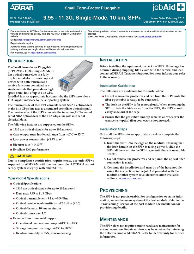
The Small Form-Factor Pluggable Small Form-Factor Pluggable
Long Reach 11.3 Gbps LR-2 DWDM 80 km XFP is a full duplex
serial electric, serial optic device with both transmit and receive
functions contained in a single module. These XFPs support
operations over a wide temperature range, and are suitable for
use in outside plant environments. They provide a high speed
serial link of up to 11.3 Gbps to support SONET/SDH (OC192/
STM64), Ethernet (10 GE), OTN (OTU2/OTU2e) and Fibre
Channel (10 G FC). The LR-2 XFP operates on various optical
channels. Installed in the appropriate host module, the LR-2 XFP
provides a 10 Gigabit interface to the supporting system.
The transmit side of the LR-2 XFP converts serial NRZ electrical
data at the 10 Gbps line rate to a standard compliant optical
signal. The receive side converts the incoming DC balanced serial
NRZ optical data at the 10 Gb/s line rate into serial electrical data.
Refer to the table on page 2 for the part numbers, channels and
wave lengths supported by these XFPs.
NOTE
To ensure compatibility, refer to the documentation provided
with the host module.
FEATURES
The following features are supported on the LR-2 XFP:
Optical signals for up to 80 km reach
Low power consumption (<3.5 W max)
CAUTION
!
Due to compliance certification requirements, only SFP supplied
by ADTRAN are to be used with the host module. ADTRAN
cannot certify system integrity with other SFP.
Small Form-Factor Pluggable
11.3 Gbps LR-2 DWDM 80 km
INSTALLATION
Before installation, inspect the LR-2 XFP. If damage has occurred
during shipping, file a claim with the carrier, and then contact
ADTRAN Customer Support. For more information, refer to
“Warranty”.
Installation Guidelines
The following are guidelines for this installation.
The latch on the LR-2 XFP is for removal only. When removing
the LR-2 XFP, rotate the latch away from the LR-2 XFP. The
LR-2 XFP should slide easily out of the cage.
It is recommended that the connector plug remain on
whenever the transceiver optical fiber connector is not
inserted.
Installation Steps
To install the LR-2 XFP, complete the following steps:
1. Insert the LR-2 XFP into the SFP cage on the circuit board of
the host module with the latch handle facing outward. Slide
the LR-2 XFP all the way into the cage.
2. Exert adequate pressure to ensure the LR-2 XFP is
completely seated in the LR-2 XFP cage.
3. Do not remove the connector plug until the optical fiber
connection is made.
4. Continue the installation and turn-up of the host module.
Product P/N: 144298XGX
Issue Date: September 2014
Document P/N: 6144298XGX-22C
Documentation for ADTRAN Carrier Networks products is available for
viewing and download directly from the ADTRAN Support Community
website.
Go to: https://supportforums.adtran.com/welcome
Registration is required.
ADTRAN offers training courses on our products, including customized
training and courses taught at our facilities or at customer sites.
For inquiries, go to: http://adtran.com/training
The following documents provide additional information for this product:
SFP/XFP/SFP+ Compatibility Matrix and Engineering Guide
26144298XGX-22C
SPECIFICATIONS
Channel Spacing: 100 GHz
Data Rate: 9.95 Gbps to 11.35 Gbps
Optical distance: 80 km maximum
Transmit Wavelength: See Supported Modules Table
Receive Wavelength: 1270 to 1600 nm
Optical transmit levels: –1.0 to +3.0 dBm
Spectral width: 1 nm
Extinction Ratio: 8.2 dB
Max Optical receive level: –7.0 dBm
Receiver Damage Threshold: –7.0 dBm
Optical Path Penalty: 2 dB
Receive Sensitivity:
o–24 dBm @ 9.95 Gbps, 10e–12 BER
o–28 dBm @ 10.7 Gbps, 10e–4 BER
o–27 dBm @ 11.1 Gbps, 10e–4 BER
o–26.5 dBm @ 11.35 Gbps, 10e–4 BER
OSNR (Dispersion –360 to 1440 ps/nm)
o–25.5 dB @ 9.95 Gbps, 10e–12BER
o–20 dB @ 10.7 Gbps, 10e–4BER
o–20 dB @ 11.1 Gbps, 10e–4BER
o–21 dB @ 11.35 Gbps, 10e–4BER
Minimum Span Attenuation: 10 dB
Optical Budget
o21 dB @ 9.95 Gbps, 10e–12BER
o25 dB @ 10.7 Gbps, 10e–4BER
o24 dB @ 11.1 Gbps, 10e–4BER
o23.5 dB @ 11.35 Gbps, 10e–4BER
Dispersion Tolerance: –360 to 1440 ps/nm
Optical connectors: LC
Extended Environmental Support:
oOperational temperature range: –40°C to +85°C
oStorage temperature range: –40°C to +85°C
Relative humidity up to 85%, noncondensing
SUPPORTED MODULES
This Job Aid supports the modules listed in the following table:
Channel Number Wave Length Part Number CLEI
Channel 17 1563.86 nm 1442982G8 BVL3AUMD_ _
Channel 18 1563.05 nm 1442982G9 BVL3AUND_ _
Channel 19 1562.23 nm 1442983G1 BVL3AUPD_ _
Channel 20 1561.42 nm 1442983G2 BVL3AURD_ _
Channel 21 1560.61 nm 1442981G1 BVL3AT5D_ _
Channel 22 1559.79 nm 1442981G2 BVL3AT6D_ _
Channel 23 1558.98 nm 1442981G3 BVL3AT7D_ _
Channel 24 1558.17 nm 1442981G4 BVL3AT8D_ _
Channel 25 1557.36 nm 1442981G5 BVL3AT9D_ _
Channel 26 1556.55 nm 1442981G6 BVL3AUAD_ _
Channel 27 1555.75 nm 1442981G7 BVL3AUBD_ _
Channel 28 1554.94 nm 1442981G8 BVL3AUCD_ _
Channel 29 1554.13 nm 1442981G9 BVL3AUDD_ _
Channel 30 1553.33 nm 1442982G1 BVL3AUED_ _
Channel 31 1552.52 nm 1442982G2 BVL3AUFD_ _
Channel 32 1551.72 nm 1442982G3 BVL3AUGD_ _
Channel 33 1550.92 nm 1442982G4 BVL3AUHD_ _
Channel 34 1550.12 nm 1442982G5 BVL3AUJD_ _
Channel 35 1549.32 nm 1442982G6 BVL3AUKD_ _
Channel 36 1548.51 nm 1442982G7 BVL3AULD_ _
Channel 37 1547.72 nm 1442983G3 BVL3AUSD_ _
Channel 38 1546.92 nm 1442983G4 BVL3AUTD_ _
Channel 39 1546.12 nm 1442983G5 BVL3AUUD_ _
Channel 40 1545.32 nm 1442983G6 BVL3AUVD_ _
Channel 41 1544.53 nm 1442983G7 BVL3AUWD_ _
Channel 42 1543.73 nm 1442983G8 BVL3AUXD_ _
Channel 43 1542.94 nm 1442983G9 BVL3AUYD_ _
Channel 44 1542.14 nm 1442986G1 BVL3AUZD_ _
Channel 45 1541.35 nm 1442986G2 BVL3AU0D_ _
Channel 46 1540.56 nm 1442986G3 BVL3AU1D_ _
Channel 47 1539.77 nm 1442986G4 BVL3AU2D_ _
Channel 48 1538.98 nm 1442986G5 BVL3AU3D_ _
Channel 49 1538.19 nm 1442986G6 BVL3AU4D_ _
Channel 50 1537.40 nm 1442986G7 BVL3AU5D_ _
Channel 51 1536.61 nm 1442986G8 BVL3AU6D_ _
Channel 52 1535.82 nm 1442986G9 BVL3AU7D_ _
Channel 53 1535.04 nm 1442987G1 BVL3AU8D_ _
Channel 54 1534.25 nm 1442987G2 BVL3AU9D_ _
Channel 55 1533.47 nm 1442987G3 BVL3AVAD_ _
Channel 56 1532.68 nm 1442987G4 BVL3AVBD_ _
Channel 57 1531.90 nm 1442987G5 BVL3AVCD_ _
Channel 58 1531.12 nm 1442987G6 BVL3AVDD_ _
Channel 59 1530.33 nm 1442987G7 BVL3AVED_ _
Channel 60 1529.55 nm 1442987G8 BVL3AVFD_ _
6144298XGX-22C 3
SAFETY AND REGULATORY COMPLIANCE
WARNING
!
Read all warnings and cautions before installing or servicing this
equipment.
CAUTION
C
This product uses a Class 1 Laser module that complies with 21
CFR 1040.10 and 1040.11 and IEC 60825-1 and -2. For continued
compliance with the above standards, install only ADTRAN-
approved Class 1 Laser Modules in this product. For a list of
ADTRAN-approved SFPs and XFPs, see
adtran.com>support>support community>search SFP/XFP.
ADTRAN cannot certify system integrity with other laser
modules
CAUTION
!
Electrostatic Discharge (ESD) can damage electronic modules.
When handling modules, wear an antistatic discharge wrist
strap to prevent damage to electronic components. Place
modules in antistatic packing material when transporting or
storing. When working on modules, always place them on an
approved antistatic mat that is electrically grounded.
Per GR-1089-CORE this product is designed and intended for
installation as part of a Common Bonding Network (CBN).
This product is not designed nor intended for installation as
part of an Isolated Bonding Network (IBN).
Per GR-1089-CORE Section 9, this product does not have an
internal DC connection between -48 VR and frame ground.
This product can be installed in a DC-I (isolated) or DC-C
(common) installation. For installations where other cards or
the host system have internal connections between -48 VR and
frame ground, the system would be intended for deployment
only in a DC-C installation.
The chassis frame ground terminal must be connected to an
earth ground to ensure that the metal enclosure of the SFP/
XFP is properly grounded via the backplane connector.
NOTE
The Gigabit Ethernet port(s) are optical and therefore are not
classified as any type of port as defined in Appendix B of GR-
1089-CORE.
This product is compliant with SFF-8472 Digital Diagnostics
Monitoring Interface for Optical Transceivers, Revision 9.3.
This product is compliant with the XFP Multi-Source
Agreement (MSA).
This product is designed to be deployed in GR-3108-CORE
environmental Class 1 and 2 as defined in GR-3108-CORE.
This product meets or exceeds all the applicable requirements of
NEBS, Telcordia GR-63-CORE, GR-1089-CORE, and ETSI EN
300368. This product is intended for deployment in Central Office
type facilities, EEEs, EECs, and locations where the NEC applies
(for example, Customer Premises).
This product is to be installed in ADTRAN products in Restricted
Access Locations only, and installed by trained service personnel.
This device complies with Part 15 of the FCC rules. Operation is
subject to the following two conditions:
1. This device may not cause harmful interference
2. This device must accept any interference received, including
interference that may cause undesired operation.
Changes or modifications not expressly approved by ADTRAN
could void the user's authority to operate this equipment.
This product is designed to meet the following environmental
classes:
ETSI EN 300 019-1-1 “Classification of environmental
conditions; Storage Class” 1.2
ETSI EN 300 019-1-2 “Classification of environmental
conditions, Transportation”, Class 2.3
ETSI EN 300 019-1-3 “Classification of environmental
conditions, Stationary use at weatherprotected locations”,
Class 3.3
This product is designed to function without degradation during
exposure to all test severities per Class 3.3 of ETSI EN 300 019-1-3.
This product meets EU RoHS Directive 2002/95/EC and/or
applicable exemptions. Refer to www.adtran.com for further
information on RoHS/WEEE.
CAUTION!
SUBJECT TO ELECTROSTATIC DAMAGE
OR DECREASE IN RELIABILITY
HANDLING PRECAUTIONS REQUIRED
Warranty: ADTRAN will replace or repair this product within the warranty period if it does not
meet its published specifications or fails while in service. Warranty information can be
found online at www.adtran.com/warranty.
©2014 ADTRAN, Inc. All Rights Reserved.
ADTRAN CUSTOMER CARE:
From within the U.S. 1.800.726.8663
From outside the U.S. +1 256.963.8716
PRICING AND AVAILABILITY 1.800.827.0807
*6144298XGX-22C*

Other ADTRAN Cables And Connectors manuals

ADTRAN 1184544P5 User manual

ADTRAN

ADTRAN 1184544P5 User manual

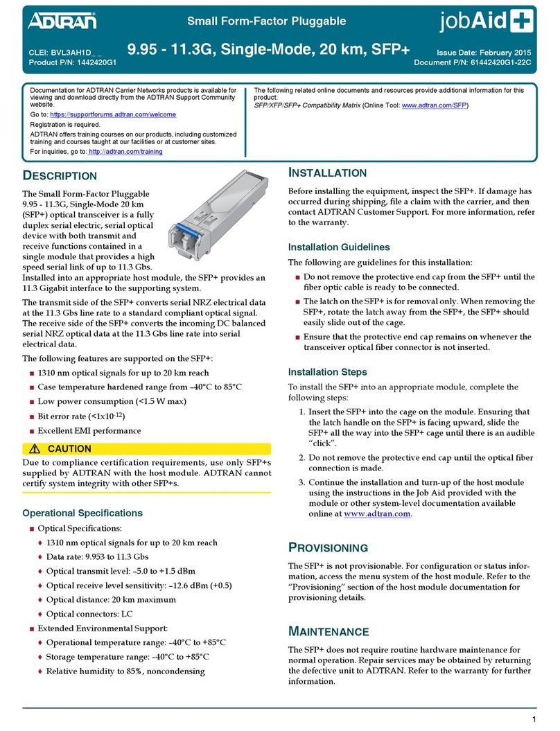
ADTRAN BVL3AH1D Series User manual

ADTRAN

ADTRAN BVL3AH1D Series User manual

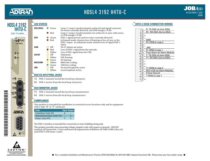
ADTRAN 3192 HDSL4 Operating instructions

ADTRAN

ADTRAN 3192 HDSL4 Operating instructions

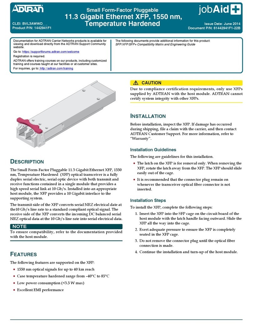
ADTRAN BVL3AWWD Series User manual

ADTRAN

ADTRAN BVL3AWWD Series User manual

ADTRAN 1442520G1 User manual

ADTRAN

ADTRAN 1442520G1 User manual

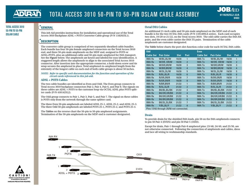
ADTRAN Total Access 3010 User manual

ADTRAN

ADTRAN Total Access 3010 User manual

ADTRAN GPON User manual

ADTRAN

ADTRAN GPON User manual

ADTRAN Total Access 5000 User manual

ADTRAN

ADTRAN Total Access 5000 User manual

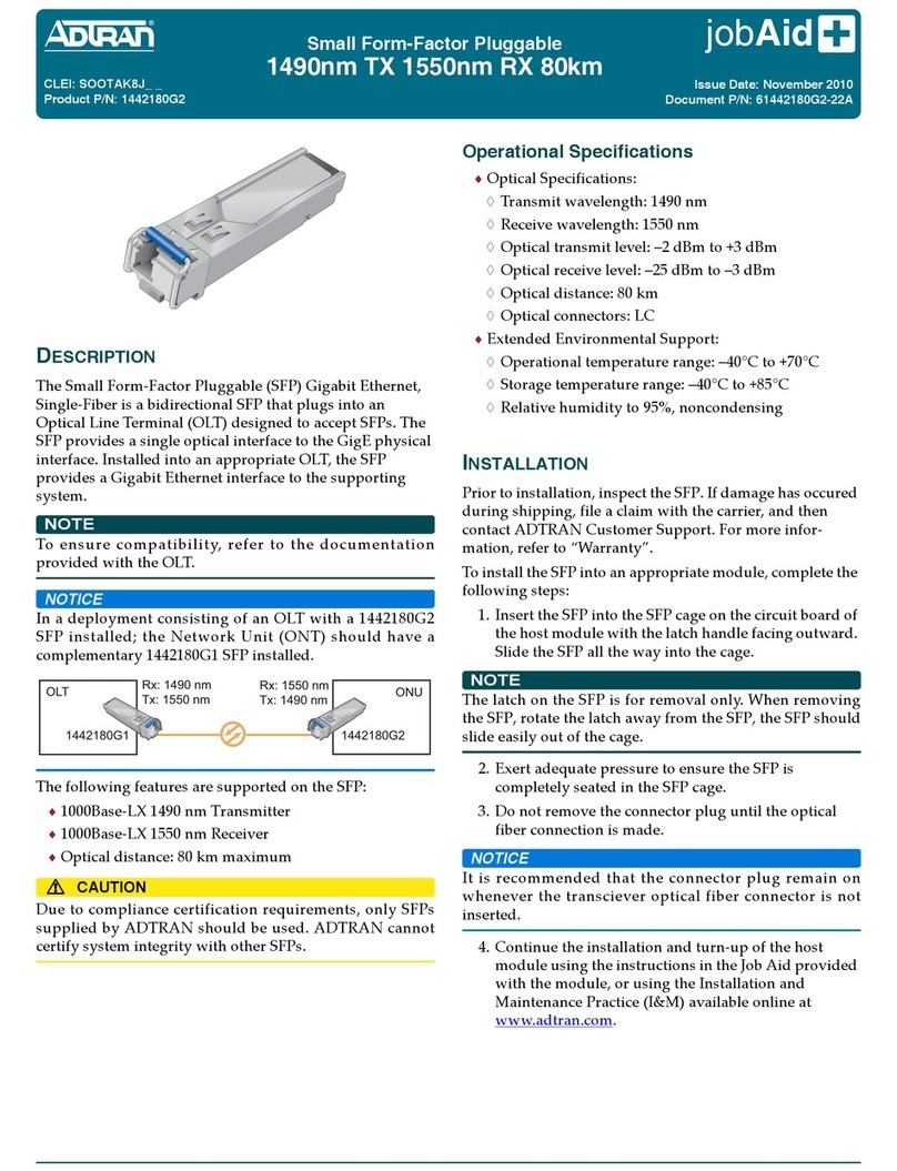
ADTRAN SOOTAK8J Series User manual

ADTRAN

ADTRAN SOOTAK8J Series User manual

ADTRAN 1184561P4 User manual

ADTRAN

ADTRAN 1184561P4 User manual

ADTRAN BVL3AH0D Series User manual

ADTRAN

ADTRAN BVL3AH0D Series User manual

ADTRAN Cable Kit Tracer 3202 User manual

ADTRAN

ADTRAN Cable Kit Tracer 3202 User manual

ADTRAN 1442200G1 User manual

ADTRAN

ADTRAN 1442200G1 User manual

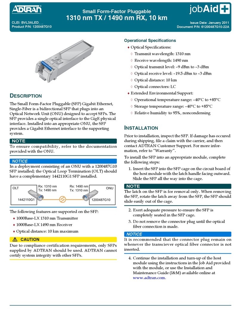
ADTRAN jobAid+ 1200487G10 User manual

ADTRAN

ADTRAN jobAid+ 1200487G10 User manual

ADTRAN 1184544P2 User manual

ADTRAN

ADTRAN 1184544P2 User manual

ADTRAN 1200487G80 User manual

ADTRAN

ADTRAN 1200487G80 User manual

ADTRAN 1445003F1 User manual

ADTRAN

ADTRAN 1445003F1 User manual

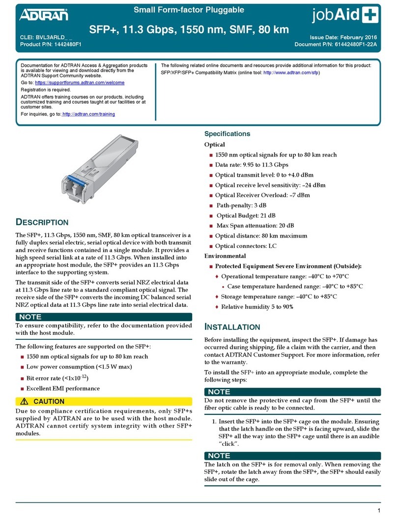
ADTRAN BVL3ARLD Series User manual

ADTRAN

ADTRAN BVL3ARLD Series User manual

Popular Cables And Connectors manuals by other brands

Seneca SG-EQ4 installation manual

Seneca

Seneca SG-EQ4 installation manual

Philips SWA3522W Specifications

Philips

Philips SWA3522W Specifications

Emos P1412ST manual

Emos

Emos P1412ST manual

Lindy 43098 user manual

Lindy

Lindy 43098 user manual

Sanus ELM806 manual

Sanus

Sanus ELM806 manual

Flair 858080 instruction manual

Flair

Flair 858080 instruction manual

Patton electronics 80 user manual

Patton electronics

Patton electronics 80 user manual

Festo KMP3 Series Assembly instructions

Festo

Festo KMP3 Series Assembly instructions

Masimo LNOP MP Series manual

Masimo

Masimo LNOP MP Series manual

Tripp Lite S054-45I Specification sheet

Tripp Lite

Tripp Lite S054-45I Specification sheet

Delta YDY-5X4.0 user manual

Delta

Delta YDY-5X4.0 user manual

BZB Gear BG-UHD-DA1x24 user manual

BZB Gear

BZB Gear BG-UHD-DA1x24 user manual

Tripp Lite N352-03M Specification sheet

Tripp Lite

Tripp Lite N352-03M Specification sheet

ABB OTDC800-1000F Series installation instructions

ABB

ABB OTDC800-1000F Series installation instructions

Jensen Iso-Max JT-MS-8N2 user manual

Jensen

Jensen Iso-Max JT-MS-8N2 user manual

Kramer WP-220E user manual

Kramer

Kramer WP-220E user manual

Heitronic 45608 Installation and operating instructions

Heitronic

Heitronic 45608 Installation and operating instructions

Watts 009-FS installation instructions

Watts

Watts 009-FS installation instructions

manuals.online logo
manuals.online logoBrands
  • About & Mission
  • Contact us
  • Privacy Policy
  • Terms and Conditions

Copyright 2025 Manuals.Online. All Rights Reserved.