Weidmüller Klippon TB MH Instruction Manual

R.T.Nr. 1194340000/02/08.11
Assembly guidelines – empty enclosures 3
Montagerichtlinien – Leergehäuse 11
Consignes de montage - coffrets vides 19
Instrucciones de montaje de armarios vacíos
27
Istruzioni di montaggio – custodie vuote 35
Руководство по монтажу – пустые корпуса 43
Klippon® TB MH
II 2 G Ex e IIC Gb
II 2 D Ex tb IIIC Db IP66/67
IEC 60079-0:2007; EN 60079-0:2009
IEC 60079-7:2006; EN 60079-7: 2007
IEC 60079-31:2008; EN 60079-31:2009
IECEx KEM 10.0015U
KEMA 10ATEX0046U


3
Empty enclosures characteristics
Material: Stainless Steel 316L / 1.4404; 304 / 1.4301;
Mild steel painted
Temperature: -60°C…. +135°C
IP-Rating IP 66/67 (IP 67 max .Temp.: 105°C)
ATEX use: The complete assembled enclosure must be certied
by a recognised, notied body and in line with the ATEX
directives!

4
Mounting the Enclosure
a (mm) b (mm) c (mm) d (mm) e (mm)
KTB xx 2215xx 292 152 38.5 215 28*
KTB xx 2626xx 260 260 45 170 28*
KTB xx 3030xx 306 306 51.5 203 28*
KTB xx 3526xx 350 260 51.5 247 28*
KTB xx 4030xx 400 300 76.5 247 28*
KTB xx 4538xx 458 382 76.5 305 28*
KTB xx 4848xx 480 480 76.5 327 28*
KTB xx 5535xx 550 350 100 350 28*
KTB xx 6245xx 620 450 100 420 28*
KTB xx 7650xx 762 508 127 508 28*
KTB xx 9161xx 914 610 177.5 559 28*
KTB xx 9874xx 980 740 177.5 625 28*
* subtract 15 mm if the enclosure is not tted with gland plates
on side C or D

5
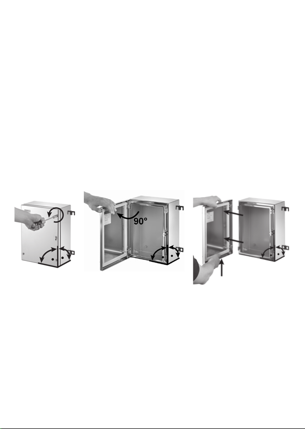
Opening of the Enclosure
Place enclosure in a vertical upright position. Loosen the lid cover xings
screws with a suitable tool (refer to diagram 1 below). After loosening the
covers screws, the lid can be opened up to approximately 130°.
Removing the lid
The lid should be removed by loosening the cover xing screws and any
attached lid bonding cable with a suitable tool. After loosening the xing
screws the cover lid must be opened to a 90° position (refer to diagram 2
below). With the lid in this position, lift the lid slightly and slide to the outside
to release (refer to diagram 3 below). In this way you are able to x the lid
to either the left or the right hand side of the enclosure (multi hinge version
only). If the lid position is to be xed to another side, it is also necessary to
reposition the padlock lug to the opposite side. Do not remove the captive
element of the screws!
1 2 3
Removing gland plates
If gland plates are to be used remove them by loosening the gland plate
screws with a suitable tool. Afterwards the plates can be detached.
Closing the enclosure
Ensure that all lid, gland plate, earth stud screws are fully tightened in a
crosswise manor after installation.
Tightening Values
Lid & Gland plates (when present) 2.5 Nm
M10 earth stud (out-/inside) 15.0 Nm
M6 earth stud inside 6.0 Nm

6
Fitting Cable Glands
Drilling Information
The permissible areas for drilling are indicated in the table below. In each
case if the required ingress protection rating (IP) is stated on the certica-
tion label (ATEX or IECEx), the stated IP rating must be maintained.
The permissible drilling area (the shaded area) in the drawing
above is the same for an enclosure that is supplied either with or
without a gland plate.
For enclosures that are larger than size KTB MH 765015, the drill-
ing areas on sides C and D are based on two separate gland zones.
The separation area is 60 mm. Note: Whether gland plates are tted
or not, this separation area has to be taken into account!

7
Drilling Information (Gland Plate Only)
The available area of the drilling zone for each individual gland plate is de-
tailed below:
drilling zone gland placement diameter drilling diameter
The allowed drilling zone is 22 mm in distance from the outer edges
of each plate.
Within the indicated drilling zone, various cable entries can be drilled based
on the following table and conditions:
Drilling Diameter +0.2 mm
-0.0 mm
Gland Placement Diameter
(mm)
M16 16.0 22.4
M20 20.0 28.0
M25 25.0 35.0
M32 32.0 44.8
M40 40.0 56.0
M50 50.0 70.0
M63 63.0 88.2
M75 75.0 105.0

8
Drilling Diameter +0.2 mm
-0.0 mm
Gland Placement Diameter
(mm)
PG7 13.0 18.2
PG9 15.0 21.0
PG11 19.1 26.7
PG13,5 20.9 29.3
PG16 23.0 32.2
PG21 28.8 40.3
PG29 37.5 52.5
PG36 47.5 66.5
PG42 54.5 76.3
PG48 59.8 83.7
• Drill holes using the specied drilling diameters and gland placement di-
ameters. (See table above)
• When using gland plates, only 20% of the material may be removed.
(Note: For guidance, ensure a minimum distance of at least 15 mm be-
tween the individual gland placement diameters.)
• When drilling directly into the enclosure (lid or body) only 10% of the ma-
terial from each individual side may be removed.
(Note: For guidance, ensure a minimum distance of at least 30 mm be-
tween the individual gland placement diameters.)
• If locknuts are to be used, it is essential to decrease the drilling area by
the additional area of the locknut.
• When drilling, avoid ANY deformation, overheating of the enclosure or
gland plate. Ensure that the hole ( the cable gland) is sealed afterwards
according to the relevant ingress protection rating (IP).

9
Internal/External Earth Stud Assembly
The drawing below provides a prole of the earth stud.
G F E A C B D G E F G
outside enclosure inside enclosure
A 1 x earth bolt M10
B 1 x washer Ø 20 mm t = 2 mm
C 1 x silicone O- Ring
D 1 x washer (lug) Ø 20 mm
E 2 x clamping bracket
F 2 x washer (lug) Ø 15 mm
G 3 x nut M10 Torque: 15 Nm
Lid Earth Screw Assembly
Attach the cable lug to the earth screw followed by the spring washer and
tighten the complete assembly with a nut (with a torque of 6.0 Nm).

10
Inspection, Maintenance and Repairs
WARNING
Disconnect power supply before installing or servicing these
enclosures.
Ensure that only authorized and trained personnel perform repairs and
maintenance work.
For an Ex-certied enclosure the training has included the instruction of the
various types of protection and installation practices, the relevant rules and
regulations.
Inspection / Maintenance
After opening an enclosure, a visual inspection of the lid and gland plate
gasket must be performed to ensure no foreign objects may interfere with
the enclosure sealing function. A visual inspection of the apparatus shall be
carried out in a method appropriate to the installation environment.
Inspection should include verication that all lid and gland plate screws
(where tted) are secured with the proper torque. Checks should also in-
clude that there is no ingress (dust or liquid) inside the enclosure and that
all cable glands and main earth connections are in good condition.
Cleaning
The enclosure should be cleaned with a damp cloth. Do not clean the enclo-
sure with hydrocarbonbased cleaning compounds!
Repair
Only parts authorized by the manufacturer (such as mounting plates, earth
studs and gland plates) may be used for replacements and modications.

11
Technische Daten des Leergehäuses
Material: Edelstahl 316L / 1.4404; 304 / 1.4301; Stahlblech lackiert
Temperatur: -60° C .... +135° C
IP-Schutzklasse: IP 66/67 (IP 67, max. Temp.: 105° C)
ATEX-Einsatz: Das vollständig zusammengebaute Gehäuse muss durch
eine anerkannte, benannte Organisation bescheinigt
werden und sich im Einklang mit den ATEX-Richtlinien
benden!

12
Montage des Gehäuses
a (mm) b (mm) c (mm) d (mm) e (mm)
KTB xx 2215xx 292 152 38,5 215 28*
KTB xx 2626xx 260 260 45 170 28*
KTB xx 3030xx 306 306 51,5 203 28*
KTB xx 3526xx 350 260 51,5 247 28*
KTB xx 4030xx 400 300 76,5 247 28*
KTB xx 4538xx 458 382 76,5 305 28*
KTB xx 4848xx 480 480 76,5 327 28*
KTB xx 5535xx 550 350 100 350 28*
KTB xx 6245xx 620 450 100 420 28*
KTB xx 7650xx 762 508 127 508 28*
KTB xx 9161xx 914 610 177,5 559 28*
KTB xx 9874xx 980 740 177,5 625 28*
* 15 mm müssen abgezogen werden, wenn das Gehäuse nicht mit
Flanschplatten auf der Seite C oder D ausgerüstet ist.

13
Öffnen des Gehäuses
Stellen Sie das Gehäuse aufrecht in eine vertikale Position. Lösen Sie die
Deckelschrauben mit einem geeigneten Werkzeug (siehe nachfolgende Ab-
bildung 1). Nachdem Lösen der Deckelschrauben kann der Deckel bis auf
ca. 130° geöffnet werden.
Entfernen des Deckels
Der Deckel sollte durch Lösen der Deckelbefestigungsschrauben mit einem ge-
eigneten Werkzeug geöffnet werden. Nachdem Lösen der Deckelschrauben
muss der Deckel bis auf ca. 90° geöffnet werden (siehe nachfolgende Abbildung
2). Heben Sie, wenn sich der Deckel in dieser Position bendet, diesen etwas
an, und schieben Sie ihn zum Entfernen nach außen (siehe nachfolgende Abbil-
dung 3). Hierdurch können Sie den Deckel entweder rechts oder links am Ge-
häuse befestigen (nur bei der Multi-Scharnier-Version). Muss der Deckel an ei-
ner anderen Seite befestigt werden, ist es ebenfalls erforderlich, den Vorhänge-
schlossbügel auf die andere Seite zu montieren. Entfernen Sie nie die Halteele-
mente der Schrauben!
1 2 3
Entfernen der Flanschplatten
Die Flanschplatten werden nach dem Lösen der Flanschplattenschrauben
mit einem geeigneten Werkzeug abgenommen. Anschließend können die
Platten abgenommen werden.
Schließen des Gehäuses
Stellen Sie nach der Installation sicher, dass alle Deckel, Flanschplatten und
Erdungsbolzenschrauben vollständig und über Kreuz angezogen wurden.
Anzugswerte
Deckel und Flanschplatten (wenn vorhanden) 2,5 Nm
M10-Mutter (innen/außen) 15,0 Nm
M6-Erdungsbolzen innen 6,0 Nm

14
Einsetzen der Kabelverschraubungen
Bohrinformationen
Die zulässigen Bereiche für Bohrungen sind in der nachstehenden Tabelle
aufgeführt. In jedem Fall muss, wenn die erforderliche Schutzart (IP) auf
dem Typenschild (ATEX oder IECEx) aufgeführt ist, die angegebene IP-
Schutzart beibehalten werden.
Der zulässige Bohrungsbereich (die schraferte Fläche) in der
obigen Zeichnung entspricht der eines Gehäuse, das wahlweise mit
oder ohne Kabelverschraubungsplatte geliefert wird.
Bei Gehäusen über der Größe KTB MH 765015 basieren die Boh-
rungsbereiche an den Seiten C und D auf zwei getrennten Kabel-
verschraubungsbereichen. Die Trenndistanz beträgt 60 mm. Hin-
weis: Die Trenndistanz muss, unabhängig davon, ob das Gehäuse
mit Flanschplatten bestückt ist oder nicht!

15
Bohrinformationen (nur Flanschplatte)
Die verfügbare Fläche des Bohrbereichs für jede einzelne Flanschplatte ist
nachfolgend aufgeführt:
Bohrungsbereich Kabelverschraubungs- Bohrdurchmesser
Sitzdurchmesser
Der zulässige Bohrungsbereich besitzt einen Abstand von 22 mm
zu den äußeren Rändern jeder Platte.
Innerhalb des gekennzeichneten Bohrungsbereichs können verschiedene
Kabelverschraubungen auf der Grundlage der nachstehenden Tabelle und
Bedingungen gebohrt werden:
Bohrdurchmesser +0,2 mm
-0,0 mm
Kabelverschraubungs-
Sitzdurchmesser (mm)
M16 16,0 22,4
M20 20,0 28,0
M25 25,0 35,0
M32 32,0 44,8
M40 40,0 56,0
M50 50,0 70,0
M63 63,0 88,2
M75 75,0 105,0

16
Bohrdurchmesser +0,2 mm
-0,0 mm
Kabelverschraubungs-
Sitzdurchmesser (mm)
PG7 13,0 18,2
PG9 15,0 21,0
PG11 19,1 26,7
PG13, 5 20,9 29,3
PG16 23,0 32,2
PG21 28,8 40,3
PG29 37,5 52,5
PG36 47,5 66,5
PG42 54,5 76,3
PG48 59,8 83,7
• Fertigen Sie Bohrungen mit dem angegebenen Bohrdurchmesser und
Kabelverschraubungs-Sitzdurchmesser an. (siehe vorstehende Tabelle)
• Bei Verwendung von Flanschplatten dürfen nur 20% des Materials ent-
fernt werden. (Hinweis: Sorgen Sie, als Richtlinie, für einen minimalen
Abstand von mindestens 15 mm zwischen den einzelnen Kabelver-
schraubungs-Sitzdurchmessern.)
• Beim Bohren direkt in das Gehäuse (Deckel oder Körper) darf nur 10%
des Materials von jeder einzelnen Seite entfernt werden.
(Hinweis: Sorgen Sie, als Richtlinie, für einen minimalen Abstand von
mindestens 30 mm zwischen den einzelnen Kabelverschraubungs-Sitz-
durchmessern.)
• Werden Kontermuttern verwendet, ist es unerlässlich, den Bohrungsbe-
reich um die zusätzliche Fläche der Kontermuttern verringern.
• Vermeiden Sie beim Bohren jede Verformung oder Überhitzung des Ge-
häuses oder der Flanschplatten. Stellen Sie sicher, dass das Loch (die
Kabelverschraubung), entsprechend der jeweiligen Schutzart (IP), abge-
dichtet wird.

17
Zusammensetzen des internen / externen Erdungsbol-
zens
Die nachfolgende Zeichnung stellt ein Prol des Erdungsbolzens dar.
G F E A C B D G E F G
Gehäuseaußenseite Gehäuseinnenseite
A 1 x Erdungsbolzen M10
B 1 x Unterlegscheibe Ø 20 mm t = 2 mm
C 1 x Silikon-O- Ring
D 1 x Unterlegscheibe (mit Rändelung) Ø 20 mm
E 2 x Klemmhalterungen
F 2 x Unterlegscheibe (mit Rändelung) Ø 15 mm
G 3 x Mutter M10 Drehmoment: 15 Nm
Zusammensetzen der Deckelerdungsschraube
Befestigen Sie den Erdungskabelschuh an der Schraube, gefolgt von der
Federscheibe, und sichern Sie die diese Einheit mit einer Mutter (Anzugs-
drehmoment 6,0 Nm).

18
Inspektion, Wartung und Reparaturen
WARNUNG
Schalten Sie die Versorgung vor der Installation oder Wartung
dieses Gehäuses ab.
Stellen Sie sicher, dass nur autorisiertes und geschultes Personal Repara-
turen und Wartungsarbeiten durchführt.
Für einen Ex-zertiziertes Gehäuse beinhaltete die Ausbildung Anwei-
sungen für die verschiedenen Arten von Schutz- und fachgerechten Installa-
tionen, die einschlägigen Richtlinien und Vorschriften.
Inspektion / Wartung
Nehmen Sie nach dem Öffnen eines Gehäuses eine visuelle Inspektion
der Deckel- und Flanschplattendichtung vor, um sicherzustellen, das keine
Fremdkörper die Gehäusedichtfunktion beeinträchtigen. Für die Sichtprü-
fung des Gerätes sollte ein geeignetes, der Installationsumgebung entspre-
chendes Verfahren angewendet werden.
Die Prüfung sollte auch beinhalten, dass alle Deckel- und Flanschplatten-
schrauben (falls vorhanden) mit dem richtigen Drehmoment angezogen
sind. Es sollte ebenfalls geprüft werden, dass weder Staub noch Flüssig-
keiten in das Innere des Gehäuses eingedrungen sind sowie dass sich alle
Kabelverschraubungen und die Haupterdungsanschlüsse in gutem Zustand
benden.
Reinigung
Das Gehäuse sollte mit einem feuchten Tuch gereinigt werden. Reinigen
Sie das Gehäuse nicht mit einem auf Kohlenwasserstoff basierenden Reini-
gungsmittel!
Reparatur
Nur durch den Hersteller zugelassene Teile (wie Montageplatten, Erdungs-
bolzen und Kabelverschraubungsplatten) dürfen für den Ersatz und Modi-
kationen genutzt werden.

19
Caractéristiques des coffrets vides
Matière : Acier inoxydable 316L / 1.4404; 304 / 1.4301;
tôle d’acier laqué
Température : -60 °C…. +135 °C
Classement IP IP 66/67 (IP 67 : temp. max. : 105 °C)
Utilisation ATEX : Le coffret monté complet doit être homologué par un
organisme reconnu en conformité avec les directives
ATEX

20
Montage du coffret
a (mm) b (mm) c (mm) d (mm) e (mm)
KTB xx 2215xx 292 152 38.5 215 28*
KTB xx 2626xx 260 260 45 170 28*
KTB xx 3030xx 306 306 51.5 203 28*
KTB xx 3526xx 350 260 51.5 247 28*
KTB xx 4030xx 400 300 76.5 247 28*
KTB xx 4538xx 458 382 76.5 305 28*
KTB xx 4848xx 480 480 76.5 327 28*
KTB xx 5535xx 550 350 100 350 28*
KTB xx 6245xx 620 450 100 420 28*
KTB xx 7650xx 762 508 127 508 28*
KTB xx 9161xx 914 610 177.5 559 28*
KTB xx 9874xx 980 740 177.5 625 28*
* Enlever 15 mm si le coffret n'est pas équipé de presse-étoupe sur le côté
C ou le côté D
Table of contents
Languages:
Other Weidmüller Enclosure manuals
Popular Enclosure manuals by other brands

Enginuity
Enginuity OnSite WR-10U23 manual

CommScope
CommScope Mini-OTE 200 Series Installation instruction

Pioneer
Pioneer UD-SW120D instruction manual

TROJAN PRO
TROJAN PRO FORTIS CASES operating instructions

CalDigit
CalDigit HDPro2 Getting started

Hubbell
Hubbell Killark USF Series INSTALLATION, OPERATION & MAINTENANCE DATA SHEET