Weir HYDRAU-FLO HF1105Z0001 User manual

Weir Minerals Multiflo®
Safety Solutions for Liquid Filling
HYDRAU-FLO®FUEL FILLING SYSTEM
Installation, Operation and Maintenance Manual
Document Number:
Revision: 0
Issue Date: 23 February 2015
CONTROLLED DOCUMENT
Copyright © 2015, Weir Minerals Australia Ltd. All rights reserved
.
Installation, Operation and Maintenance Manual
Copyright © 2015, Weir Minerals Australia Ltd trading as Weir Minerals Multiflo®. All rights reserved.
MULTIFLO, VACTRONIC and HYDRAU-FLO are registered trademarks of Weir Minerals Australia Ltd. This
document contains information which is confidential to Weir Minerals Australia Ltd. It should not be disclosed
in whole or in part to parties other than the recipient without the express written permission of Weir Minerals
Australia Ltd authorized personnel.

Weir Minerals Multiflo®
Safety Solutions for Liquid Filling
HYDRAU-FLO®FUEL FILLING SYSTEM
Installation, Operation and Maintenance Manual
Document Number:
Revision: 0
Issue Date: 23 February 2015
CONTROLLED DOCUMENT
Copyright © 2015, Weir Minerals Australia Ltd. All rights reserved
.
HYDRAU-FLO®COMPONETS ARE ONLY
RATED FOR THEIR INTENDED USE.

Weir Minerals Multiflo®
Safety Solutions for Liquid Filling
HYDRAU-FLO®FUEL FILLING SYSTEM
Installation, Operation and Maintenance Manual
Document Number:
Revision: 0
Issue Date: 23 February 2015
CONTROLLED DOCUMENT
Copyright © 2015, Weir Minerals Australia Ltd. All rights reserved
.
Revision History
Revision
Description
Reviewed
Authorised
Date

Weir Minerals Multiflo®
Safety Solutions for Liquid Filling
HYDRAU-FLO®FUEL FILLING SYSTEM
Installation, Operation and Maintenance Manual
Document Number:
Revision: 0
Issue Date: 23 February 2015
CONTROLLED DOCUMENT
Copyright © 2015, Weir Minerals Australia Ltd. All rights reserved
.
Contact Details
Head Office
Equipment Placement Sales and Services
170 Kewdale Road
Kewdale WA 6105
Ph: 08 9479 4988
Fax: 08 9479 4588
Email: [email protected]
PT Weir Minerals Multiflo®
Jl Mulawarman No 29A RT
003 Batakan Kecil Kelurahan Manggar
Balikpapan 76117
East Kalimantan
Indonesia
Ph: 62 542 746098
Fax: 62 542 746099
Banjarbaru Branch Office
Jl. Ahmad Yani Km 33,6 Ruko
No. 04 RT.
003 RW.001 Kelurahan
Loktabat Selatan
Banjarbaru 70712
South Kalimantan
Indonesia
Ph: 62 511 4773027
62 511 4772357
Fax: 62 511 477 3583

HYDRAU-FLO®
Document Number:
Revision: 0
CONTROLLED DOCUMENT
Copyright © 2015, Weir Minerals Australia Ltd. All rights reserved
.
Page 1-3
Issue Date: 23 February 2015
Table of Contents
Contact Details..................................................................................................................................................................ii
Australia.............................................................................................................................................................................ii
Indonesia ...........................................................................................................................................................................ii
Table of Contents...........................................................................................................................................................1-3
List of Figures ................................................................................................................................................................1-6
List of Tables..................................................................................................................................................................1-7
1Introduction..........................................................................................................................................................1-1
1.1 Disclaimer ........................................................................................................................................................1-1
1.2 Copyright..........................................................................................................................................................1-1
1.3 Warranty...........................................................................................................................................................1-1
1.4 Intended Audience...........................................................................................................................................1-1
2Safety....................................................................................................................................................................2-2
2.1 Safety Symbols................................................................................................................................................2-3
2.2 General Safety.................................................................................................................................................2-5
2.3 Qualified Workers ............................................................................................................................................2-5
2.4 Safe Working....................................................................................................................................................2-5
2.5 Safety Equipment.............................................................................................................................................2-5
2.6 Risks ................................................................................................................................................................2-5
2.7 Operating Conditions .......................................................................................................................................2-6
2.8 Material Safety Data Sheets............................................................................................................................2-6
2.9 Intended Use of the Product............................................................................................................................2-6
2.10 Unintended Use of the Product........................................................................................................................2-6
2.11 Warranty...........................................................................................................................................................2-7
3Description...........................................................................................................................................................3-9
3.1 Hydrau-Flo®Fuel Filling Valve.........................................................................................................................3-9
3.2 Working Principle.............................................................................................................................................3-9
3.3 Hydrau-Flo®Configurations ...........................................................................................................................3-11
3.3.1 Hydrau-Flo®Range of Fuel Fillings Valves............................................................................................3-11
3.3.2 Hydrau-Flo®Float Control Valves..........................................................................................................3-13
3.3.3 Hydrau-Flo®Anti-Surge Breathers.........................................................................................................3-14
3.3.4 Hydrau-Flo® Lever Float Control Valve..................................................................................................3-15
3.4 Hydrau-Flo® Hardware ...................................................................................................................................3-16
3.4.1 Hydrau-Flo®Black Fuel Filling Valve Adaptors......................................................................................3-16
3.4.2 Hydrau-Flo®Blue, Gold and Red Fuel Filling Valve Adaptors...............................................................3-17
3.4.3 Pilot Line Hose Fittings and Accessories...............................................................................................3-18
3.4.4 Breather Line Connectors......................................................................................................................3-19
3.4.5 Exhaust Line Float Control Valves and Breather Hose, Fittings and Accessories................................3-19
3.4.6 Pilot Line ................................................................................................................................................3-20
3.5 Optional Features ..........................................................................................................................................3-21
3.5.1 Internal Pilot Lines .................................................................................................................................3-21

HYDRAU-FLO®
Document Number:
Revision: 0
CONTROLLED DOCUMENT
Copyright © 2015, Weir Minerals Australia Ltd. All rights reserved
.
Page 1-4
Issue Date: 23 February 2015
3.5.2 Anchoring Pilot Lines .............................................................................................................................3-21
3.5.3 Vertical Float Extensions .......................................................................................................................3-22
3.5.4 Lever Float (Fixed) Connections............................................................................................................3-23
3.5.5 Hydrau-Flo®Applications.......................................................................................................................3-24
3.6 Hydrau-Flo®Valves Dimensions....................................................................................................................3-24
4Installation..........................................................................................................................................................4-25
4.1 Pre-Installation...............................................................................................................................................4-25
4.2 Installation Tool Kit.........................................................................................................................................4-25
4.3 Installation Procedure –To suit General Installation.....................................................................................4-26
4.4 Installation Procedure –To suit CAT D10R/D11R Dozers............................................................................4-27
4.5 Installation Procedure - To suit CAT 16H Grader..........................................................................................4-28
4.6 Additional Information on Installation.............................................................................................................4-29
4.6.1 General Arrangement ............................................................................................................................4-29
4.6.2 Multiple Filling Valves with Single Lever Float Valve.............................................................................4-30
4.6.3 Multiple Filling Valves with Single Vertical Float Valve..........................................................................4-31
4.6.4 Check Valve Arrangement.....................................................................................................................4-32
4.6.5 Lever Float Height Adjustment...............................................................................................................4-32
5Commissioning..................................................................................................................................................5-33
6Operation............................................................................................................................................................6-34
6.1 Fuel Filling......................................................................................................................................................6-34
6.2 Flow Specification..........................................................................................................................................6-34
6.3 Fuel Filling of Dual Tanks ..............................................................................................................................6-34
6.4 Multiple Filling Valves Flow Rating ................................................................................................................6-34
6.5 Suitable Mediums ..........................................................................................................................................6-35
6.6 Fuel Consumption..........................................................................................................................................6-35
6.7 Fuel Reticulation ............................................................................................................................................6-35
6.8 Float Control...................................................................................................................................................6-35
7Maintenance.......................................................................................................................................................7-36
7.1 Maintenance Instructions...............................................................................................................................7-36
7.2 Troubleshooting Guide...................................................................................................................................7-37
8Appendices ........................................................................................................................................................8-38
8.1 Commissioning Checklist...............................................................................................................................8-38
8.2 Maintenance Checklist...................................................................................................................................8-39
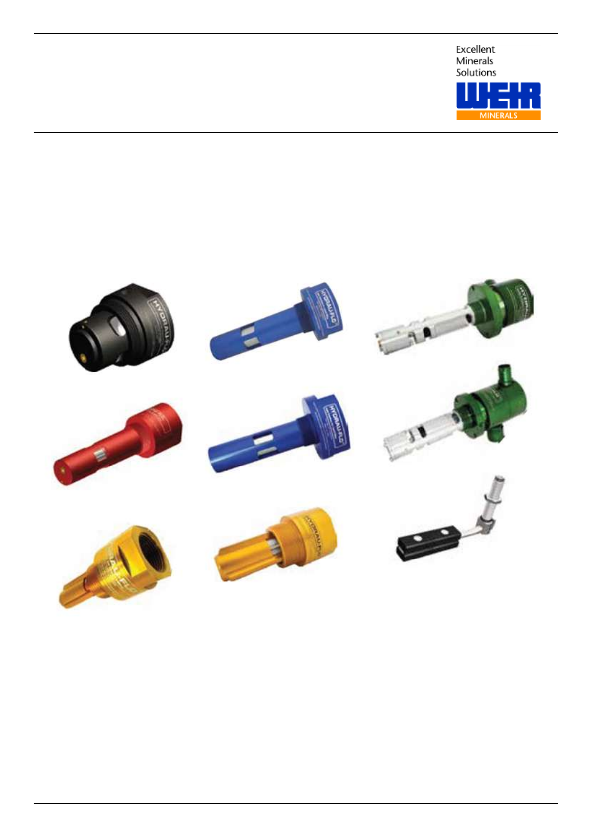
8.3 Black Valve with Hydrau Flo®Receiver.........................................................................................................8-40
8.4 Red Valve in Adapter with Hydrau Flo®Receiver..........................................................................................8-41
8.5 Blue Valve with Hydrau Flo®Receiver...........................................................................................................8-42
8.6 Single Receiver and Single Vertical Float (Mobile) General Arrangement....................................................8-43
8.7 Single Receiver and Single Lever Float (Stationary) General Arrangement.................................................8-44
8.8 Lever Float Dimension Drawing.....................................................................................................................8-45
8.9 Fuel Lever Float Settings...............................................................................................................................8-46
8.10 Vertical Float Drawing....................................................................................................................................8-47
8.11 Float Control Valve Drawing (Catch Tank Option).........................................................................................8-48

HYDRAU-FLO®
Document Number:
Revision: 0
CONTROLLED DOCUMENT
Copyright © 2015, Weir Minerals Australia Ltd. All rights reserved
.
Page 1-5
Issue Date: 23 February 2015
8.12 Catch Tank Option with Breather Option Drawing.........................................................................................8-49
8.13 Vertical Float Shutoff Point Drawing..............................................................................................................8-50
8.14 Vertical Float Shutoff Point Drawing..............................................................................................................8-51
8.15 Check Valve Selection Drawing.....................................................................................................................8-52
8.16 Black Valve Drawing......................................................................................................................................8-53
8.17 Red Valve Drawing ........................................................................................................................................8-54
8.18 Blue Filter Valve Drawing...............................................................................................................................8-55
8.19 Gold Valve Drawing.......................................................................................................................................8-56
8.20 Environmental Exposure Certificate ..............................................................................................................8-57
8.21 Explosive Atmospheres Certification .............................................................................................................8-58
8.22 Hydrau-Flo®Parts List ...................................................................................................................................8-59
8.23 Hydrau-Flo®Deliverables...............................................................................................................................8-61

HYDRAU-FLO®
Document Number:
Revision: 0
CONTROLLED DOCUMENT
Copyright © 2015, Weir Minerals Australia Ltd. All rights reserved
.
Page 1-6
Issue Date: 23 February 2015
List of Figures
Figure 3-1: Working Principle of a Mobile and Stationary Fuel Filling Set-up.................................................................3-9
Figure 3-2: Operation of Hydrau-Flo®Fuel Filling System (Vertical Float Not Shown) ................................................3-10
Figure 3-3: Roll Over Protection ....................................................................................................................................3-14
Figure 3-4: Hydrau-Flo®Pilot Line Arrangement for Vertical and Lever Float Control Valves ......................................3-20
Figure 3-5: Converting External Pilot Line to an Internal Line.......................................................................................3-21
Figure 3-6: Hydrau-Flo®Pilot Line Magnet Anchor........................................................................................................3-21
Figure 3-7: Barrel Extensions (300mm and 150mm Extensions Shown)......................................................................3-22
Figure 3-8: Trickle Feed System with Two Floats .........................................................................................................3-24
Figure 4-1: Multiple Filling Valves with Single Lever Float and Check Valve................................................................4-30
Figure 4-2: Multiple Filling Valves with Single Vertical Float and Check Valve.............................................................4-31
Figure 4-3: Check Valve Arrangement ..........................................................................................................................4-32

HYDRAU-FLO®
Document Number:
Revision: 0
CONTROLLED DOCUMENT
Copyright © 2015, Weir Minerals Australia Ltd. All rights reserved
.
Page 1-7
Issue Date: 23 February 2015
List of Tables
Table 2-1: Safety Colours................................................................................................................................................2-3
Table 2-2: Safety Symbols...............................................................................................................................................2-4
Table 3-1: Fuel Filling Valves ........................................................................................................................................3-11
Table 3-2: Float Control Valves .....................................................................................................................................3-13
Table 3-3: Anti-Surge Breathers....................................................................................................................................3-14
Table 3-4: Lever Float Control Valve.............................................................................................................................3-15
Table 3-5: Black Valve Adaptors ...................................................................................................................................3-16
Table 3-6: Black, Gold and Red Valve Adaptors...........................................................................................................3-17
Table 3-7: Pilot Line Hose Fittings and Accessories .....................................................................................................3-18
Table 3-8: Breather Line Connectors.............................................................................................................................3-19
Table 3-9: Exhaust Line Accessories ............................................................................................................................3-19
Table 3-10: Lever Float Extensions...............................................................................................................................3-23
Table 4-1: Installation Tool Kit .......................................................................................................................................4-25
Table 4-2: General Arrangement for Single Receiver and Single Valve .......................................................................4-29
Table 7-1: Troubleshooting Guide .................................................................................................................................7-37

Document Number:
Revision: 0
CONTROLLED DOCUMENT
Copyright © 2015, Weir Minerals Australia Ltd. All rights reserved
.
Page 1-1
Issue Date: 23 February 2015
HYDRAU-FLO®Valves
Introduction
1 Introduction
The purpose of this Manual is to advise and instruct installers, and operators of Weir Minerals Hydrau-Flo®Fuel Filling
System regarding the recommended installation, operation and maintenance of the equipment. The following
information will aid you in the installation, operation and maintenance of your new Weir Minerals Hydrau-Flo®Fuel
Filling System. To ensure long life and trouble-free operation, it is imperative that the instructions contained in these
manuals are read understood and carried out by all users of this product.
The Weir Minerals Hydrau-Flo®Fuel Filling System is of robust construction and is used to prevent build-up of pressure
and overfilling in the fuel tank. It has been designed to be used in conjunction with the existing “fast fill” systems and
also the traditional splash filling systems. The Hydrau-Flo®Valve Kits are manufactured to suit a wide range of
industrial applications in the mining, oil and gas, transport, construction and maritime sectors. Configurations are
designed for individual equipment needs.
Please check our website www.weirminerals.com/hydrau-flo or search YouTube®for “Hydrau-Flo®“to view the
promotional animation video on how the system works.
1.1 Disclaimer
Despite of the care taken to compile all information and illustration in this document, neither the author nor the
publisher can be held liable for any consequential damages resulting from possible errors in this publication.
The English language was used to write the original manual. Any versions in other languages are translation of the
original manual instructions. These translated versions may contain information that differs from the original due to
interpretation of the content and meaning of the original text. In the case of such discrepancies, the original English
language instructions will be considered the sole authentic source for the purpose of determining the content and
meaning of the text.
Weir Minerals Multiflo®reserves the right to make changes to technical and design specifications at the any time
without prior notice.
1.2 Copyright
Weir Minerals Multiflo®Pty Ltd 2015
This document is subject to copyright. Use or copying of this document in whole or part without the written permission
of Weir Minerals Multiflo®constitutes an infringement of copyright.
1.3 Warranty
All Hydrau-Flo®Fuel Filling Valve components are covered with a 36 month manufacturer warranty. It is not
recommended that unauthorised personnel service the Hydrau-Flo® components and may result a void of warranty. For
information regarding servicing or warranty claims, please contact Weir Minerals Multiflo® on the contact details
provided at the beginning of this manual.
1.4 Intended Audience
This manual is intended for:
Personnel who have a relevant basic level of trade/professional competency.
CAUTION
PERSONNEL INJURY
The Hydrau-Flo®components must be installed and operated by personnel who are trained and have
sufficient knowledge about the hazards that may occur during operations.

Document Number:
Revision: 0
CONTROLLED DOCUMENT
Copyright © 2015, Weir Minerals Australia Ltd. All rights reserved
.
Page 2-2
Issue Date: 23 February 2015
HYDRAU-FLO®
Safety
2 Safety
Weir Minerals Hydrau-Flo®Fuel Filling System has been designed to provide a safe working environment for operators,
maintenance personnel and to be used in environmentally sensitive areas where “zero-spill” is mandatory. The
instructions within this manual must be followed and carried out accordingly to ensure a safe and efficient operation.
Good, Robust Health, Safety and Environmental Systems, Process and Practices are undoubtedly an important
aspect of operating safely.
Read the instruction manual prior to installing or operation.
Personal Protective Equipment (PPE) must be used when installing, operating, servicing, maintaining this
equipment.
It is the user’s responsibility to be aware of and comply with all federal and state occupational health and safety
requirements or the safety regulatory organisation having jurisdiction.
Use trained competent people to assess all site risks involved with the installation of this equipment in
accordance with the Installation and Operations Manual.
Use the correct, safe and appropriate equipment related to the site conditions.
SAFETY WARNINGS AND PRECAUTIONS ARE PROVIDED IN THIS SECTION. FAILURE TO HEED THESE
WARNINGS AND PRECATIONS MAY RESULT IN PERSONAL INJURY AND/OR DEATH TO YOURSELF AND/OR
OTHERS ALONG WITH THE RESULTS OF EQUIPMENT AND ENVIRONMENTAL DAMAGES.
Living by our five key safety values and commitment to following safety procedures will enable us all to make the work
place a safer environment. Our Five Key Safety Values are:
My colleagues and my own safety are paramount;
No task is so important or urgent that it cannot be undertaken safely;
I will only undertake tasks that I am trained, competent and properly prepared for;
I will never cut corners, nor take shortcuts at the expense of safety;
I will stop the job if I believe it is unsafe to continue.
Any aspect of the installation, which the Customer is unsure of, we advise the customer to discuss with a Weir
Minerals Multiflo®Representative.

Document Number:
Revision: 0
CONTROLLED DOCUMENT
Copyright © 2015, Weir Minerals Australia Ltd. All rights reserved
.
Page 2-3
Issue Date: 23 February 2015
HYDRAU-FLO®
Safety
2.1 Safety Symbols
The safety colours incorporated in this manual are indicated in Table 2-1. These colours serve as a guide to the
associated risk with the given safety symbols.
Table 2-1: Safety Colours
Signal
Warning Level
Description
Danger
Indicates a hazard with high level of risk
which, if not avoided, could result in death
or catastrophic equipment damage.
DANGER
Warning
Indicates a hazard with a medium level of
risk which, if not avoided, could result in
serious or moderate injury, or serious
equipment damage.
WARNING
Caution
Indicates a hazard with a low level of risk
which, if not avoided, could result in
moderate or minor injury, or moderate
equipment damage.
CAUTION
Notice
Indicates important information for the
user.
NOTICE

Document Number:
Revision: 0
CONTROLLED DOCUMENT
Copyright © 2015, Weir Minerals Australia Ltd. All rights reserved
.
Page 2-4
Issue Date: 23 February 2015
HYDRAU-FLO®
Safety
The accompanying documentation supplied with the Weir Minerals Hydrau-Flo®Fuel Filling System utilises the
following safety symbols listed in Table 2-2 to highlight potential harmful situations to personnel, equipment and the
environment as per ISO 9001:2008.
Table 2-2: Safety Symbols
SYMBOL
DEFINITIONS
CONSEQUENCES
Imminent risk of fatal or
crippling injuries
Fatal or crippling injuries likely to
result from any exposure.
Possibility of a harmful
situation
Minor or slight injuries possible.
Mandatory Instructions
Failure to follow may lead to fatality,
injuries or damage to property and
environment.
Prohibited activities
Possible damage to the product,
equipment’s or property.
Warning of Electrical
shock
Fatal or crippling injuries likely to
result from any exposure.
Mandatory Personal
Protective Equipment’s
Fatal or crippling injuries likely to
result if not worn.
Explosion Warning
Possibility of explosion if
instructions not followed.
Application Hints and
other useful Information
Refer other
User has to refer accompanying
manuals or other documents.

Document Number:
Revision: 0
CONTROLLED DOCUMENT
Copyright © 2015, Weir Minerals Australia Ltd. All rights reserved
.
Page 2-5
Issue Date: 23 February 2015
HYDRAU-FLO®
Safety
2.2 General Safety
Use of the Hydrau-Flo®Components for an application in an environment other than defined at the time of purchase is
strictly prohibited and can result in a hazardous situation. The Hydrau-Flo®Components may only be installed and
operated by persons who are competent and are aware of the dangers of working with it.
These instructions are intended to facilitate familiarisation with the product and its permitted use. Operating the product
in compliance with these instructions is important to help ensure reliability in service and avoid risks. These instructions
may not take into account local regulations. It is the responsibility of the purchaser of the product to ensure such
regulations are observed by all, including those installing the product. Always coordinate repair activities with
operations personnel and follow all plant safety requirements, applicable workplace health and safety laws and
regulations. The equipment must not be put into service until all the conditions relating to workplace health and safety
in the instructions are met.
Information in these user instructions is believed to be reliable. Despite of all the efforts to provide correct and
necessary information the content of this manual may appear insufficient and is not guaranteed as to its completeness
or accuracy.
It is not permitted to make changes to the Hydrau-Flo®components without permission from Weir Minerals Multiflo®. If
any changes are made to the product without permission, Weir Minerals Multiflo®disclaims all liability.
2.3 Qualified Workers
All personnel involved in the installation operation and inspection of the Hydrau-Flo®Components must be qualified to
carry out the work involved. If the personnel in question do not already possess the necessary knowledge and skill,
appropriate training and instruction must be provided by a suitable qualified trainer.
If required, the operator may engage the manufacturer/supplier to provide applicable training.
Always coordinate repair activities with operations and workplace health and safety personnel and follow plant safety
requirements and applicable workplace health and safety laws and regulations.
2.4 Safe Working
All standard safety precautions for such equipment must be followed before and during installation, operation, and
maintenance. Drain the fuel tanks and isolate pipework before installation. The appropriate workplace health and safety
precautions must be taken. All metal mating faces must be cleaned of dirt, rust, paint and other adhering substances
prior to installation. Failure to clean parts can affect installation and running clearances and could lead to premature
failure of parts.
2.5 Safety Equipment
The correct safety equipment (PPE) and safety instructions must be carried out accordingly in assigned areas. It is the
User’s responsibility to carry out assigned safety rules. If any incidents/accidents occur due to unsafe act the User’s
held liable for all cause and responsibilities.
2.6 Risks
It is the User’s responsibility to perform the risk analysis specific to the application of the site working conditions.
It is the User’s responsibility to understand all the inherent risks and consequences involved during Installation,
Operation & Maintenance procedures and take necessary precautions against such risks.
Adequate safety measures MUST be taken before performing any operation.

Document Number:
Revision: 0
CONTROLLED DOCUMENT
Copyright © 2015, Weir Minerals Australia Ltd. All rights reserved
.
Page 2-6
Issue Date: 23 February 2015
HYDRAU-FLO®
Safety
2.7 Operating Conditions
The standard filling temperature recommendation is -65°C to +45°C. If the operating range is outside the
recommended operational range, contact Weir Minerals Multiflo® for more information.
CAUTION
FAILURE DUE TO OPERATING CONDITIONS
If the Hydrau-Flo®Components are operated outside the recommended temperature range it
may cause mechanical failure leading to safety issues.
2.8 Material Safety Data Sheets
Material safety datasheets document the information on the properties of hazardous materials and how they may affect
Workplace Health and Safety. Material safety data sheets include information on the; identification of the chemical,
health hazards, safe storage and handling procedures, emergency information and disposal procedures.
Weir Minerals Multiflo®Hydrau-Flo®Components are produced with a range of materials and operate with a range of
chemicals. For specific material safety datasheets relating to the Hydrau-Flo®Components, please contact Weir
Minerals Multiflo®.
2.9 Intended Use of the Product
It is the User’s responsibility to ensure that Hydrau-Flo®Components as a whole are not used for any other purpose
other than the intended usage mentioned in this manual. The procedures followed must be in line with the technical
data and instructions provided in this manual.
It is forbidden to physically modify any Hydrau-Flo®Components. Weir Minerals Multiflo®does not take responsibility if
they are used after such modifications. If the conditions of service on the purchase order are going to be changed, it is
requested that the user seek the manufacturer’s agreement before use.
2.10 Unintended Use of the Product
Hydrau-Flo®Components must only be used for applications that are listed in the intended use section of this manual.
It is not permitted to use these components for any applications and/or field of activity other than that for which the
components were originally specified.
CAUTION
Weir Minerals Multiflo®is not responsible for incorrect use of the Hydrau-Flo®Components.

Document Number:
Revision: 0
CONTROLLED DOCUMENT
Copyright © 2015, Weir Minerals Australia Ltd. All rights reserved
.
Page 2-7
Issue Date: 23 February 2015
HYDRAU-FLO®
Safety
2.11 Warranty
If within a period of 36 months from the date of delivery (“warranty period”) the Equipment is found to be defective in
materials or workmanship, or do not conform to any applicable drawings and specifications approved in writing by Weir
Minerals Multiflo®do not perform in accordance with the current applicable water performance curves supplied as part
of the Weir quotation or published by Weir as at the date of the quotation (within the tolerances specified in applicable
Australian Standards), then Weir will, at its option, either repair or provide replacement parts or Equipment provided
that:
a) Purchaser has given written notice to Weir of any alleged defect within the warranty period;
b) Purchaser has provided Weir a reasonable opportunity to perform all appropriate tests on the Equipment;
c) The defective Equipment or parts are promptly returned to a designated Weir service centre. Any defective
Equipment or parts replaced will become Weir property and the repaired or new Equipment or parts will be
delivered free to Purchaser’s site; and
d) No warranties are given by Weir as to the performance of components other than in a test facility designated by
Weir.
For repaired Goods, excluding rubber lining, the warranty period is 6 months from the date of repair and shall only
apply to Goods or parts repaired or replaced by Weir. No separate warranty shall apply to repair Goods as a whole or
to parts not repaired or replaced by Weir. This warranty does not apply to repair of rubber
The warranties given by Weir above do not cover:
a) Fair “wear and tear”, or failures or damage not reported to Weir within the warranty period;
b) Failures or damage due to misapplication, abuse, improper installation or abnormal conditions of operation;
c) Failures or damage due to operation, either intentional or otherwise, above or below rated capacities or in an
otherwise improper manner;
d) Failures or damage resulting from Goods which have been in any way tampered with or altered by anyone
other than an authorised representative of Weir;
e) Goods damaged in shipment or without the fault of Weir;
f) Failures or damage resulting from the incorporation of, or failure of, non-Weir manufactured or supplied parts in
the Goods; or
g) Repairs to rubber lining.
Weir does not warrant any equipment or other goods of other manufacturers which is designated by Purchaser or
purchased by Weir for resale to Purchaser either separately or as a part of or operating in conjunction with equipment
or other goods manufactured by Weir. For such equipment or other goods, Purchaser must rely on the warranty given
by the manufacturer of the equipment or other goods.
When Weir supplies Services to Purchaser including laboratory testing, process development, equipment selection,
design (as part of design and manufacture), detail, contract supervision and contract management, Weir shall exercise
due care and skill in undertaking such Services. Weir’s total liability under any contract shall in no event exceed the
total price of the Goods and/or Services supplied.
If any term, condition, guarantee or warranty is implied by law, including the Australian Consumer Law, which cannot
be excluded or modified, then the term, condition, guarantee or warranty shall be deemed to be included and the
exceptions and limitations do not apply to such term, condition, warranty or guarantee, provided that Weir’s liability for
a breach of or failure to comply with any such term, condition, warranty, or guarantee (other than a guarantee under
sections 51, 52 or 53 of the Australian Consumer Law) including any consequential loss which the Purchaser may
sustain, shall be limited, at the option of Weir, to either replacing or repairing the Goods or, in the case of Services, to
supplying the Services again.
All conditions, warranties, terms, undertakings, representations, guarantees and obligations, not expressly set out in
any written contract, whether arising under statute, common law, equity, custom, trade usage or otherwise (including
without limitation, any implied condition, warranty, term, representation or guarantee as to the correspondence of the
Goods or Services with any contract description or as to merchantable quality, fitness for any purpose or safety of the
Goods or Services, or operating performance where such performance is conditional on empirical factors or on the
whole installation or on the individual or overall operation or on the skills of an operator), whether made known or not
and any liability of Weir to compensate or indemnify any person or persons in respect of the foregoing, are expressly
negatived and excluded;

Document Number:
Revision: 0
CONTROLLED DOCUMENT
Copyright © 2015, Weir Minerals Australia Ltd. All rights reserved
.
Page 2-8
Issue Date: 23 February 2015
HYDRAU-FLO®
Safety
In no event shall Weir be liable for any special, indirect, consequential, incidental or punitive losses or damages
whether in contract, tort (including without limitation negligence), equity, under statute or on any other basis, and
whether or not such loss or damage was foreseeable. The term "consequential damages" shall include, but not be
limited to, economic loss including loss of actual or anticipated profits, business interruption, loss of use, revenue,
reputation and/or data, .increased cost of working, loss or damage to equipment or other property, and liabilities of
Purchaser to its customers or third persons.
The owner of the products at all times is responsible for the correct installation and operation of the components as
prescribed in this manual. To establish that the products have been serviced and maintained as per the supplied
instructions, the owner is required to provide a complete service history in writing for the components. Refer to the
commissioning and maintenance check lists in this manual. Failure to comply with these requirements could result in
the warranty being void.
If a defect is detected, it is the responsibility of the owner to take appropriate action to stop using the components
and/or decommission it. The defect must be reported to the manufacturer directly. It is recommended that the owner
documents evidence in regards to the date in which the defect has been reported. Furthermore warranty claims can
only be considered and approved by Weir Minerals Multiflo®. For further information on warranty and warranty claims
please contact Weir Minerals Multiflo®.

HYDRAU-FLO®
Description
Document Number:
Revision: 0
CONTROLLED DOCUMENT
Copyright © 2015, Weir Minerals Australia Ltd. All rights reserved
.
Page 3-9
Issue Date: 23 February 2015
3 Description
This section shall detail the technical description and specifications for the Product.
3.1 Hydrau-Flo®Fuel Filling Valve
The Hydrau-Flo®valve system is a safer, cleaner and more reliable fuel filling valve arrangement which removes the
risk of overfilling, spillage and tank rupture while minimising safety and environmental hazards associated with fuel
transfer. With flow rates up to 1,000 litres/min (265 gallons/min) and pressures up to 100 kilopascals (20 psi), it is
imperative to provide safer solutions for fuel filling. Hydrau-Flo®Fuel Filling Systems offer superior operator protection
and improved environmental outcomes.
The Hydrau-Flo®Fuel Filling System overcomes the traditional fuel transferring problems without the need for
electronics or complex arrangements prone to blockage and failure. It incorporates robustly designed fuel filler safety
valves and float control valves to provide a reliable, hydraulically operated arrangement which depends on fluid level
rather than pressure. The system is designed to be used in conjunction with existing “fast fill” systems or traditional
“splash” filling.
Advantages of using Hydrau-Flo®Valve are:
Prevents overfilling, fuel spillage and wastage
Removes the risk of tank rupture due to pressure build up during and after filling
Minimises the risk of fire as a result of fuel spillage
Reduces costs associated with fuel wastage and equipment damage
Significantly improves safety and environmental outcomes
Reduces fuel theft.
3.2 Working Principle
The system consists of fuel filling valve, a float valve and a pilot line. The Hydrau-Flo®valve is activated via fuel level,
not the contained fuel pressure unlike traditional systems.
Figure 3-1: Working Principle of a Mobile and Stationary Fuel Filling Set-up
Fuel enters the system through a “fast fill” receiver and into the Hydrau-Flo®valve body. Fuel pressure forces the shut-
off piston open against spring pressure, allowing fuel to flow through the porting into the fuel tank. An orifice in the
piston also allows a metered amount of fuel to bleed off through a capillary line to a float valve located in the tank. This
creates a pressure drop under the piston.

HYDRAU-FLO®
Description
Document Number:
Revision: 0
CONTROLLED DOCUMENT
Copyright © 2015, Weir Minerals Australia Ltd. All rights reserved
.
Page 3-10
Issue Date: 23 February 2015
Figure 3-2: Operation of Hydrau-Flo®Fuel Filling System (Vertical Float Not Shown)
When the fuel level in the tank rises and closes the float valve, thus stopping the bleed and pressure leak, the fuel
pressure is equalised on both sides of the piston. Spring pressure will force the piston back to close the fuel ports,
preventing any extra fuel from entering the fuel tank.
NOTICE
The fuel nozzle cannot be overridden as no matter what the pressure of the fuel trying to open
the piston is, it will always be higher under the piston due to the addition of spring pressure.
By preventing over filling above the pre-set float level in the tank, an air space is maintained to allow for fuel expansion
(due to temperature rise) and thus prevent the possibility of fuel weeping through the air vents.

HYDRAU-FLO®
Description
Document Number:
Revision: 0
CONTROLLED DOCUMENT
Copyright © 2015, Weir Minerals Australia Ltd. All rights reserved
.
Page 3-11
Issue Date: 23 February 2015
3.3 Hydrau-Flo®Configurations
NOTICE
Hydrau-Flo®fuel filling valves and float control valves are available in different configurations,
designed to suit various mobile and stationary applications, majority of equipment types and
filling requirements.
3.3.1 Hydrau-Flo®Range of Fuel Fillings Valves
Table 3-1: Fuel Filling Valves
Fuel Filling Valve
(FFV)
Description:
Reference Image:
Black FFV
HF1105Z0001
1000 Lpm
264 USgpm
(3” NPS Valve
Mount)
The standard Hydrau-Flo® fuel filling black
valve is ideal for all new equipment
applications and existing equipment that has
suitable fittings. The compact design delivers
the highest flow rate capacity in the range.
Red FFV
HF1105Z0002
800 Lpm
211 USgpm
(2” NPT Male
Valve Mount)
The retro fit Hydrau-Flo®fuel filling red valve
is designed to fit into tanks using the
Wiggins®ZNC3 recess. These are typically
used on CAT®776 and 773 trucks.
Blue FFV
HF1105Z0003
800 Lpm
211 USgpm
(2” NPT Male
Valve Mount)
The most commonly used retro fit Hydrau-
Flo®fuel filling valve is the blue valve which
fits directly into truck and loader fuel tanks
using the same thread (2” NPT) as the
conventionally used dry break fittings (which
are screwed back into the Hydrau-Flo®fuel
filling valve). These valves fit into typical
CAT®and Komatsu®fuel tank recesses.
Blue FFV
HF1105Z0004
650 Lpm
171 USgpm
(1½”NPT Male
Valve Mounting)
The 1½” version of the Hydrau-Flo®fuel filling
blue valve has being designed for the
compact machinery market and underground
applications where 1½” NPT mounting are
required. Stainless steel versions are also
available for underground coal mining
applications.
This manual suits for next models
17
Table of contents
Popular Industrial Equipment manuals by other brands

SAMES KREMLIN
SAMES KREMLIN REGULEX 5 CC Installation and safety instructions

Club Cannon
Club Cannon MICRO JET MKII user manual

Seifert
Seifert 2300110 user manual

Agilent Technologies
Agilent Technologies 89400 Series Command reference

Kärcher
Kärcher HKF 200 E operating instructions

Cirs
Cirs ZEUS 008Z user guide

Jetting
Jetting MJet V2 USER GUIDE AND SAFETY INSTRUCTIONS

Siemens
Siemens RM400 C Series operating manual

Siemens
Siemens FLENDER K1N Assembly and operating instructions

Datcon
Datcon DT1102 M (PS) operating instructions

Cargo Floor
Cargo Floor CF500 SL-2 Replacement instructions

Nidec
Nidec Leroy-Somer Powerdrive MD Smart Integration guide