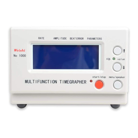
Weishi 1000 User manual

The WeiShi Multifunction Timegrapher
No.1000 User Manual
Table fo Contents
1. INSTRUMENT FUNCTION ................................. 1
2. KEYS AND DISPLAY .................................... 1
2.1 KEY FUNCTION...................................................1
2.2 PARAMETERS AND DISPLAY ...........................................2
2.3 CONNECTION ....................................................3
3. INSTALLATION ........................................ 3
3.1 THE BASIC EQUIPMENT COMPONENTS ....................................3
3.2 EQUIPMENT INSTALLATION ...........................................3
3.2.1 The Power Supply .........................................3
3.2.2 Microphone Connection ....................................4
4. OPERATION ........................................... 4
5. THE USE OF KEYS ..................................... 4
5.1 START/PAUSE KEY ................................................4
5.2 MENU/SPEAKER KEY ...............................................4
5.3 VALUE KEY↓ ...................................................4
5.4 VALUE KEY↑ ...................................................5
6. PARAMETERS .......................................... 5
6.1 BEAT NUMBERS (FREQUENCY NUMBERS) ..................................5
6.2 LIFT ANGLE ....................................................5
6.3 PERIOD........................................................6
7. TECHNICAL DATA ...................................... 6
8. COMMON FAULTS AND HANDLING .......................... 7
8.1 AFTER INSERT THE SOCKET, THE SCREEN IS DARK ..........................7
8.2 THE INSTRUMENT CAN ENTER TESTING STATE WITH THE SOUND OF “DI", BUT AFTER PLACED
THE WATCH ON THE SENSOR, THE INSTRUMENT DO NOT WORK .........................7
8.3 SIGNAL LED IS BRIGHT, BUT THE LINES IS SCATTERED OR OCCUR MANY LINES......7

1. Instrument function
The WeiShi Multifunction Timegrapher No.1000 is a precise mechanical watches test
instrument, it is used for multi-testing by watch manufacturers and watch technician.
The frequency diagram of the watch can be displayed in the LCD screen.
According to different watches, the instrument will automatically adjust optimal signal
level during testing.
The instrument will automatically calculate the rate, amplitude, beat error, and display
them by data in real time.
For the conventional beat, the instrument can automatically response; for the special
beat, can manually select.
The sampling period can selected by 2 seconds, 4 seconds, 6 seconds, 8 seconds, 12
seconds, 20 seconds, 30 seconds, 60 seconds, and the average of corresponding period
will be regard as the precise value of the watch.
Six kinds of testing position can be adjusted, and the simulation sound can be play in
the speaker or mute.
2. Keys and Display
2.1 Key Function
No.1000
value
start/stop menu/speakr
RATE AMPLITUDE BEAT ERROR
O
MULTIGUNCTION TIMEGRAPHER
sig.
PARAMETERS
22800
A
B
C
D

2
A. Start/Stop Key
The key used for start/stop to test the watch
B. Menu/Speaker Key
Selection of adjustment item or turn on/off speaker
C. Value↓Key
Selection of the next lower value or adjustment of dips’ contrast
D. Value↑Key
Selection of the next higher value or adjustment of dips’ contrast
2.2 Parameters and Display
O
A. RATE
Rate deviation in seconds per day.
B. AMPLITUDE
Display of the amplitude in degrees.
C. BEAT ERROR
Display of the beat error in ms
D. PATAMENTS
Display of the lift angle or the beat (switching by 5s)

3
2.3 Connection
A. Frequency calibration Connector
(Only the company's engineers can calibrate the frequency)
B. Sensor Connector
C. Power Switch
3. Installation
3.1 The Basic Equipment Components
Testing equipment host
Microphone
Power cable
User Manual
3.2 Equipment Installation
The instrument is to be installed in such a way that it is not exposed to direct sunlight or to
extreme temperature of 60 ℃.The microphone should be placed at a sufficient distance
from noisy machines, loudspeakers, sharp stroke sound and particularly from ultrasonic
cleaning machines. The high noise will disturb signal sensing by the microphone .
3.2.1 The Power Supply
Insert Power Cable into the mach outlet. Power supply voltage is between the 100 V~
240V.
Frequency
Calibration
Microphone
Power
C
B
A

4
3.2.2 Microphone Connection
The sensor plugs to connect to the host interface Department of sensors.
4. Operation
After connecting of the power and the sensor, the instrument will be testing status. Place the watch on
the signal sensor and the uplift of watch (leader) should the sheet metal. Test position can
be changed freely; the hand must remove from the sensor after the test position is fixed.
Green light flashing, means have received the signal of watch.
5. The Use of Keys
5.1 Start/Pause Key
Please press the Start/Pause Key, before adjusting any parameters of the instrument.
First press the Start/Pause Key one time, the instrument pause. The parameters can be
changed when green LED is off and red LED is on. After adjustment rightly, press the
Start/Pause Key again when green LED is on and red LED is off. The instrument will be
carried out the normal test and refresh the data and the screen to return to running
condition.
5.2 Menu/Speaker Key
When the instrument running, press directly the Menu/Speaker Key, can turn on or off the
speaker.
When the instrument pausing, press the Menu/Speaker Key, can enter the Menu window,
then press the Menu/Speaker Key, can select the menu item, press the Value Key ↑or↓,
can change the selected items parameters.
5.3 Value Key↓
Press the Value Key↓can decrease the LCD’s contrast, when the instrument running.
After pressed the Menu Key to select the adjustment, press the Value Key↓can select the

5
next lower parameter.
5.4 Value Key↑
Press the Value Key↑can increase the LCD’s contrast, when the instrument running.
After pressed the Menu Key to select the adjustment, press the Value Key↑can select the
next higher parameter.
6. Parameters
6.1 Beat Numbers (Frequency Numbers)
The following beat numbers are selected by automatic selection mode:
12000、14400、18000、19800、21600、25200、28800、36000、43200
(If the tested beat is not in automatically selection, the instrument will display the closest
beat number, but the test result is not correct. At this time, use the manual mode to select
the relative beat.)
Manual selection can selected out the beat number that Automatic select can not identify
and rare beat number.
The following beat are selected by Manual selection mode:
3600、6000、7200、7380、7440、7800、9000、9100、10800、11880、12000、
12342、12480、12600、13320、13440、13500、14000、14040、14160、14200、14280、
14400、14520、14580、14760、14850、15000、15360、15600、16200、16320、16800、
17196、17258、17280、17786、17897、18000、18049、18514、19332、19440、19800、
20160、20222、20944、21000、21031、21306、21600、25200、28800、32400、36000、
43200
6.2 Lift Angle
The lift angle is 52° for many common movements, therefore the lift angle value of
instrument for factory is set to 52°. This value is required to calculate the amplitude and
must be selected according to the watch movement. The lift angle can be set to between
30°and 70°.

6
6.3 Period
The measuring period selectable: 2s、4s、8s、12s、20s、30s、60s
Use to recalculate the average values of the test result.
7. Technical Data
Measuring possibilities: Rate deviation, amplitude, beat error of mechanical watches and
diagram recording of the beat noise.
Frequency numbers: It can selected out the common beat number automaticly, also can
selected out the less common beat number by manual.
Rate deviation measurement: the range of deviation is ± 999 sec / day, precision 1.0
sec/day.
Amplitude measurement: Numerical display in degrees, resolution is 1°,measuring
range: 100°to 360° (the lift angle can affect the amplitude, range: 30°to
70°.Under normal circumstances, the amplitude value do not exceed 360°.)
Measuring period times for the average numerical results: 2s, 4s, 8s, 10s, 20s, 30s, 30s,
60s.
Measuring of the Beat error(Frequency error): Numerical display in milliseconds.
Resolution is 0.1 milliseconds; the measuring range is 0-9.9 ms.
Lift Angle: the measuring range is 30 ° to 70 °, the factory set it to 52 °.
Supply voltage: single-phase AC 100 V~240V ± 10% two-line.
Measure positions: 1 to 6 positions.
Use of the environment: 0 ℃to 50 ℃, relative humidity:0 to 80% RH
Shell: Light grey plastic
Dimensions: 173×9.5×11.5mm
Weight: 402g

7
8. Common faults and handling
8.1 After insert the socket, the screen is dark
Check the power pilot LED is bright or not.
8.2 The instrument can enter testing state with the
sound of “Di", but after placed the watch on the
sensor, the instrument do not work
Check the second hand whether rotation (and amplitude must be more than 100 °),
the crown of watch (leading) is against at the sheet metal of sensor.
8.3 Signal LED is bright, but the lines is scattered or
occur many lines
Maybe the beat is mistake, adjusted the right beat (frequency) by manual
selection.
Other manuals for 1000
1
Table of contents
Other Weishi Test Equipment manuals
Popular Test Equipment manuals by other brands

Desco Europe
Desco Europe Charleswater 99090 Installation, operation and maintenance

pico Technology
pico Technology PicoVNA 106 Programmer's guide

axing
axing BZU 10-00 Operation instructions

Klein Tools
Klein Tools TraceAll VDV526-054 instruction manual

SPX
SPX Radiodetection 6100-Gfast user guide

Huazheng
Huazheng HZ1141 user manual