Fluke 707
Calibration Information
8
2. The Loop Calibrator adjustment procedure is
password protected. At this point, a password is
needed to go forward. "PAS" is displayed on the
main display and "000" on the secondary display.
Enter the password "626" as follows:
1. Rotate the knob to add a 6 in the LCD of
the secondary display, push and release
the knob.
2. Rotate the knob to get 2 into the LCD,
push and release.
3. Rotate the knob to get a 6, push and
release.
If the password is correct, you'll be led through
all the adjust modes (source, mA read, V read),
otherwise the unit returns to normal operation. In
the adjust mode, the main display will show
"1.000 mA".
3. Connect the Loop Calibrator [+] terminal to the
HP 3458A I input, and the COMterminal to the
HP 3458A LO input. The Loop Calibrator will be
in mA source cal and "1.000 mA" is displayed. On
the secondary LCD, the last 3 digits from the
knob value are shown. Adjust the mA output by
tuning the knob until "1.000 mA" shows on the HP
3458A.
4. Press , "22.000 mA" is displayed. Adjust the
mA output by turning the knob until "22.000 mA"
is shown on the HP 3458A.
5. Press to go to mA measure adjust.
6. Disconnect the HP 3458A from the Loop
Calibrator.
7. Connect the test leads from the AUX terminals of
the Fluke 5520A to the terminals on the Loop
Calibrator (black to COM and red to [+]).
8. The Loop Calibrator will display "MEASURE" and
0.000 mA is displayed. On the secondary display,
the last 3 digits of the A/D reading are shown. Set
the 5520A to output 0.000 mA into the Loop
Calibrator. Press .
9. After a moment, the Loop Calibrator will display
24.000 mA. Set the 5520A to output 24.000 mA
into the Loop Calibrator.
10. Press to go to V measure adjust.
11. Connect the test leads from the output NORMAL
terminals of the Fluke 5520A to the input
terminals on the Loop Calibrator.
12. The Loop Calibrator will display "MEASURE" and
0.000 V. The Secondary display will show the
last 3 digits of the A/D reading. Set the 5520A to
output 0.000 V into the Loop Calibrator.
13. Press . After a moment, 25.000 V will
display on the Loop Calibrator. Set the 5520A to
output 25.000 V into the Loop Calibrator.
14. Press to complete the adjustment. The
calibration counter is incremented and the
calibration data is stored. The calibration count
will be on the main display and "CAL" on the
secondary display for 2 seconds.
The calibration adjustment procedure is complete.
To see the value of the calibration counter without
calibrating the unit, hold down at power up. The
software revision number is displayed for 2 seconds
followed by the calibration counter for 2 seconds.
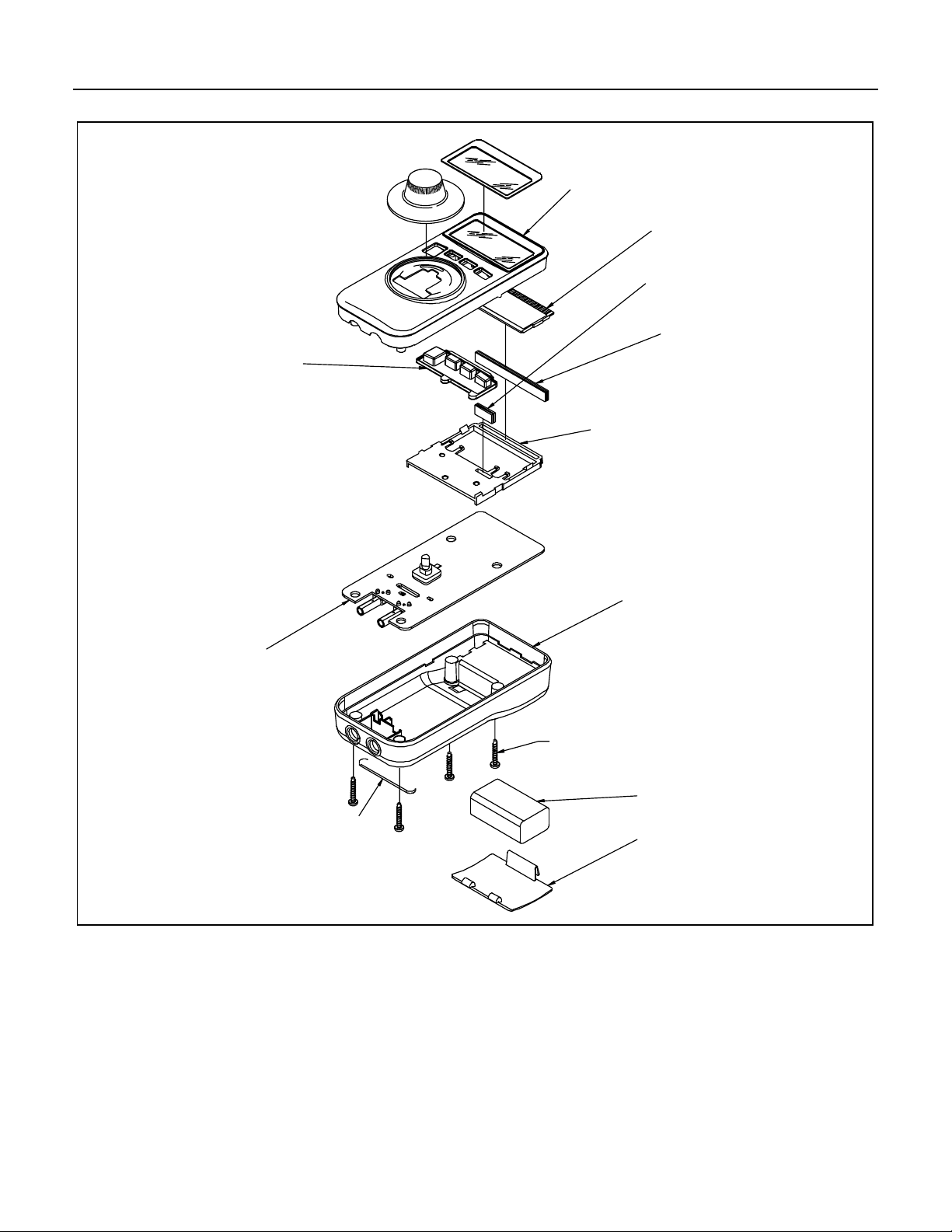
User-Replaceable Parts
User-replaceable parts, are listed in and shown in
Figure 4 and Table 5.