Welch LVSF 600 T ATEX 230 V User manual

Operation Manual
(EN)
Translation of the original operation manual
Laboratory Vacuum System
with ATEX Conformity
LVSF 600 T ATEX 230 V
LVSF 600 T ATEX 115 V
116051-10
Vers.01 | Rev.01 2022-04-13

Manufacturer
Gardner Denver Thomas GmbH
Am Vogelherd 20
98693 Ilmenau
Germany
Imprint
© 2021
Reprint or duplication, also as an
excerpt, is not permitted without written
approval from Gardner Denver Thomas
GmbH.
All rights under the copyright laws are
expressly reserved by Gardner Denver
Thomas GmbH.
We reserve the right to make changes
and amendments.
Tel.: +49 3677 604 0
Fax: +49 3677 604 131
E-mail: welch.em[email protected]om
Web: www.welchvacuum.com

Contents
Operation Manual LVSF600T-ATEX 3
Contents
1Important Information.......................................................................................5
1.1 Note for the user / personnel..........................................................................................................5
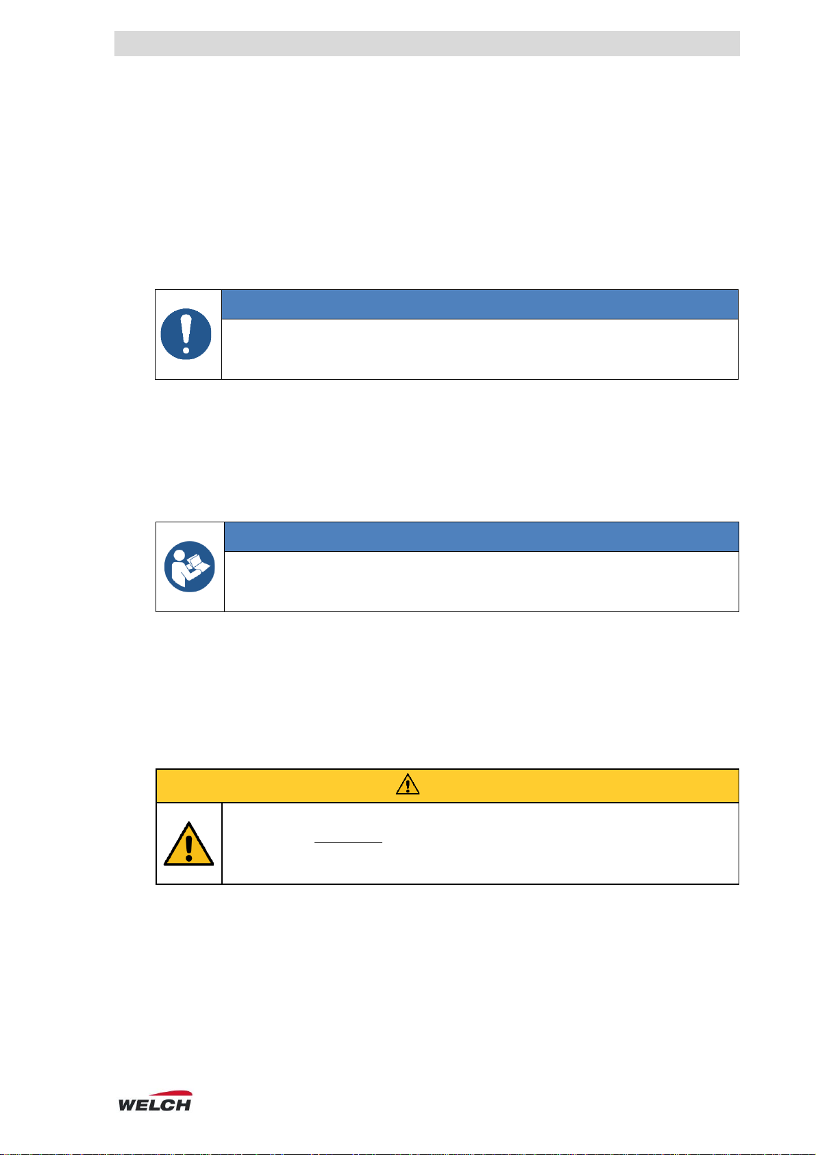
1.2 Depiction of safety and warning notices ........................................................................................6
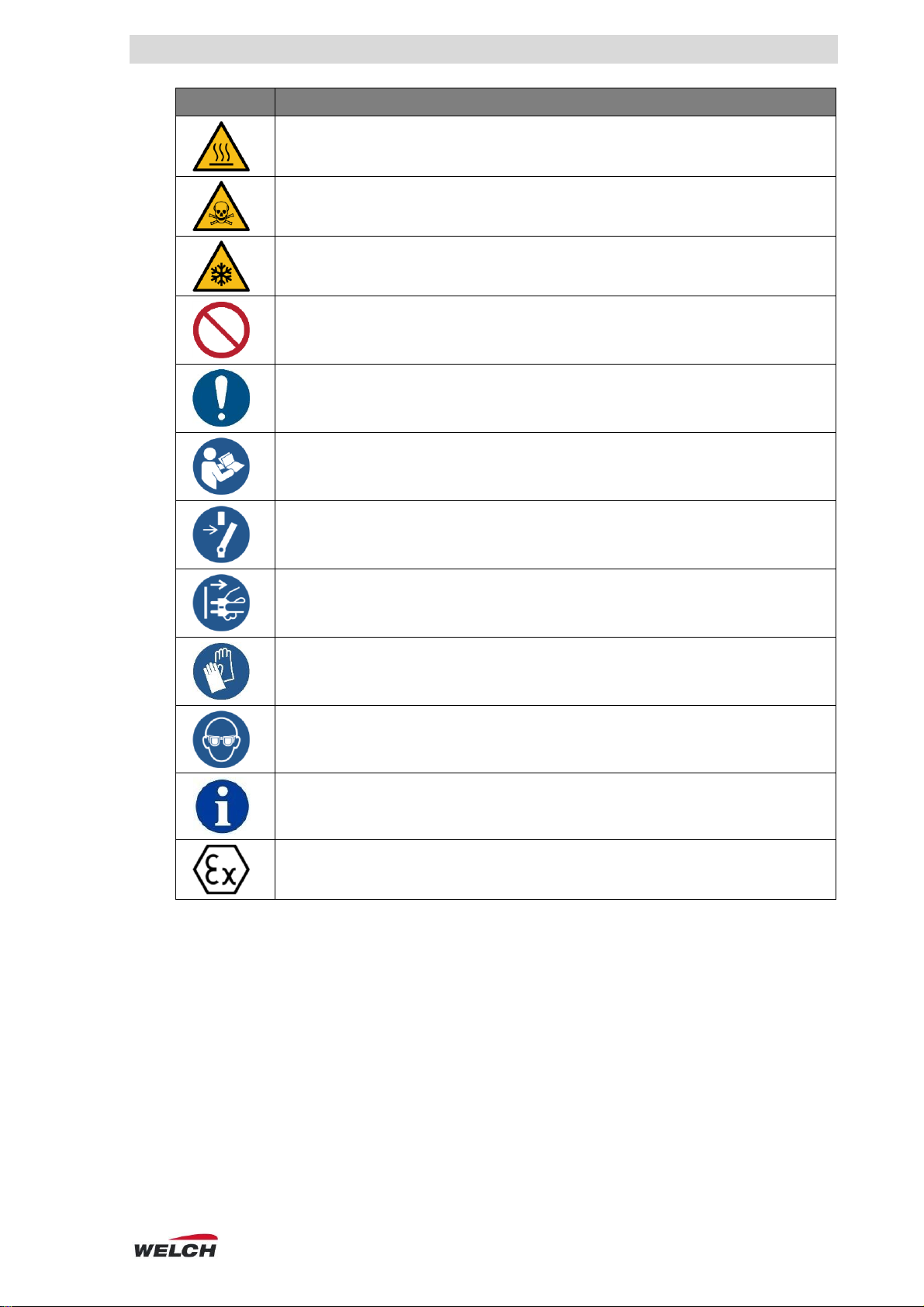
1.3 Explanations of symbols ................................................................................................................6
1.4 Legend for the abbreviations .........................................................................................................8
2Safety.................................................................................................................9
2.1 General...........................................................................................................................................9
2.1.1 Proper use..................................................................................................................................... 9
2.1.2 Improper use................................................................................................................................. 9
2.1.3 Foreseeable misuse.................................................................................................................... 10
2.2 Target groups...............................................................................................................................10
2.2.1 Personnel qualification................................................................................................................ 10
2.2.2 Overview of the responsibilities .................................................................................................. 11
2.3 Protective measures ....................................................................................................................11
2.3.1 General protective measures...................................................................................................... 11
2.3.2 Reliable operation ....................................................................................................................... 12
2.4 Special hazards............................................................................................................................12
2.4.1 Hazardous materials................................................................................................................... 13
2.4.2 Electricity..................................................................................................................................... 13
2.4.3 Mechanics................................................................................................................................... 14
2.4.4 Temperatures.............................................................................................................................. 14
2.4.5 Vacuum....................................................................................................................................... 15
2.5 ATEX application..........................................................................................................................15
2.5.1 ATEX classification ..................................................................................................................... 16
2.5.2 Special conditions ....................................................................................................................... 16
3Technical data.................................................................................................18
3.1 Dimensions...................................................................................................................................18
3.2 Characteristic values....................................................................................................................18
3.2.1 Pumping speed ........................................................................................................................... 18
3.2.2 Parameter.................................................................................................................................... 19
3.3 General information on connections ............................................................................................19
3.4 Parts in contact with medium.......................................................................................................20
4Description......................................................................................................21
4.1 Field of application .......................................................................................................................21
4.1.1 General description..................................................................................................................... 21
4.1.2Specific description ..................................................................................................................... 21
4.2 Set-up...........................................................................................................................................22
4.2.1 Front of device ............................................................................................................................ 22
4.2.2 Back of device............................................................................................................................. 23
4.2.3 Drive chamber flushing ............................................................................................................... 24
4.2.4 Gas ballast .................................................................................................................................. 24
4.2.5 Equipotential bonding.................................................................................................................. 24
4.2.6 Material........................................................................................................................................ 24
4.2.7 Motor temperature protection...................................................................................................... 25
4.3 Attachments .................................................................................................................................25

Contents
4 Operation Manual LVSF600T-ATEX
4.4 Accessories ................................................................................................................................. 25
4.4.1 Accompanying material...............................................................................................................26
4.4.2 Option..........................................................................................................................................26
5Set-up and connection................................................................................... 27
5.1 Unpacking.................................................................................................................................... 27
5.2 Set-up.......................................................................................................................................... 27
5.3 Assembly..................................................................................................................................... 27
5.4 Connecting .................................................................................................................................. 28
5.4.1 Pneumatic connection.................................................................................................................28
5.4.2 Connecting the coolant................................................................................................................29
5.4.3 Connecting the inert gas .............................................................................................................29
5.4.4 Electrical connection....................................................................................................................31
5.5 Storage........................................................................................................................................ 32
6Operation ........................................................................................................ 33
6.1 Bringing into service.................................................................................................................... 33
6.2 Safe operation............................................................................................................................. 33
6.3 End of process............................................................................................................................. 34
7Operating faults.............................................................................................. 35
8Maintenance.................................................................................................... 36
8.1 Maintenance and inspection........................................................................................................ 36
8.2 Service through cleaning............................................................................................................. 37
8.3 Repairs by the operator............................................................................................................... 38
8.3.1 Maintenance intervals .................................................................................................................38
8.3.2 Disassembly................................................................................................................................38
8.3.3 Assembly.....................................................................................................................................41
8.3.4 Functional check..........................................................................................................................41
8.4 Repairs by the manufacturer....................................................................................................... 42
8.5 Disposal....................................................................................................................................... 42
9Spare parts...................................................................................................... 43
9.1 Spare parts overview................................................................................................................... 43
9.2 Ordering and service contact ...................................................................................................... 43
10 Appendix......................................................................................................... 44
10.1 EU declaration of conformity ....................................................................................................... 44
10.2 Notes ........................................................................................................................................... 45

Important Information
Operation Manual LVSF600T-ATEX 5
1 Important Information
OBSERVE
►Read operation manual carefully before use.
►Keep operation manual for later reference.
1.1 Note for the user / personnel
Safety
The user/personnel must have read and understood the operation manual completely before
starting work.
The operation manual must always be kept in the place it will be used and be available to the
user/personnel.
The product may not be transferred without the operation manual.
Safe operation can only be guaranteed with proper and correct use of the product. The
safety and warning notices must be heeded!
General
Vacuum apparatus/vacuum system generally refers a combination of components for
vacuum applications, such as rotary evaporator with a vacuum control device and vacuum
pump.
The operator is responsible for the proper use of vacuum apparatuses/vacuum systems.
About this device
In this document, the laboratory vacuum system (abbreviated LVS) will be referred to as the
"device".
"Device" describes the entire system consisting of the integrated vacuum pump (or pump),
attachments and various other parts.
Generally, the pneumatic connections are referred to as follows:
oIntake as "suction side" toward application,
oOutlet as "pressure side" toward exhaust.
Condensate collection containers are generally referred to as separators.

Important Information
6 Operation Manual LVSF600T-ATEX
1.2 Depiction of safety and warning notices
The warning notices are depicted as follows:
DEGREE OF RISK
Additional
symbols
Type and source of danger.
Consequences if warning is not heeded.
►Measures for escaping/avoiding danger.
Degree of risk
DANGER
►Indicates a threatening risk which, if not avoid, will
result in dangerous injuries or death.
WARNING
►Indicates a possibly hazardous situation which, if
not avoided, can result in serious injuries or life-
threatening consequences.
CAUTION
►Indicates a possibly hazardous situation. If not
avoided, this can result in light injury.
Prohibition
ATTENTION
Description of the forbidden actions!
Safety notice
Additional
symbol
SIGNAL WORD
►Important instructions for the user/operator.
Actions / activities that are not allowed.
Information presentation
Signal Word
►Information for the user / operator.
1.3 Explanations of symbols
Symbol
Explanation
General warning symbol
High voltage warning
Warning of hazardous atmosphere

Important Information
Operation Manual LVSF600T-ATEX 7
Symbol
Explanation
Hot surface warning
Poisonous substances warning
Low temperature warning
General prohibition
General mandatory sign
Follow the operation manual
Disconnect prior to maintenance or repair
Disconnect the power plug.
Use gloves
Use eye protection
General information
Explosion protection

Important Information
8 Operation Manual LVSF600T-ATEX
1.4 Legend for the abbreviations
Abbreviation
Designation or meaning
Explanation
as per
as per
Designation
ESD
Electrostatic discharge
Designation
Fig.
Figure
Designation
gen.
General
Designation
pneum.
Pneumatic
Designation
MPC
Diaphragm pump, chemically resistant
(German: Membran Pumpe)
Device model
LVS
Labor vacuum system
Device model
EB
Equipotential bonding
Connection designation
EX
Exhaust
Connection designation
IN
Intake
Connection designation
KF
Small flange (German: Standard Klein-Flansch)
Connection designation
KS
Spherical joint (German: Standard Kugel-Schliff)
Connection designation
hh:mm:ss
hour / minute / second
Time specification
abs.
Absolute
Value specification
ATM
Atmosphere
Value specification
max.
Maximum
Value specification
min.
Minimum
Value specification
DN
Nominal width –inside diameter
(French: diamètre nominal)
Dimension specification
ID
Internal diameter
Dimension specification
mm
Millimeter
Dimension specification
AC
Alternating current
Electrical unit
DC
Direct current
Electrical unit
A
Ampere - current strength
Electrical unit
Hz
Hertz (frequency)
Electrical unit
V
Volt - voltage
Electrical unit
W
Watt –power
Electrical unit
hPa
Hectopascal (1 hPa = 1 mbar = 0.75 Torr)
Pressure unit
mbar
Millibar (1 mbar = 1 hPa = 0.75 Torr)
Pressure unit
Torr
Torr (1 Torr = 1.33 mbar = 1.33 hPa)
Pressure unit
EPDM
Ethylene propylene diene rubber
Material
PP
Polypropylene
Material
PTFE
Polytetrafluorethylene
Material
PVDF
Polyvinylidene fluoride
Material
PEEK
Polyetheretherketone
Material
r.H.
Relative humidity in %
Environmental condition

Safety
Operation Manual LVSF600T-ATEX 9
2 Safety
2.1 General
Anyone who plans to use the device must have read and understood the following safety
and warning notices.
Activities may only be performed by trained personnel who are familiar with the special
hazards and heed them and who have understood how the device functions as well as the
operation manual.
The device may only be used if it is in technically perfect condition.
2.1.1 Proper use
OBSERVE
►The design of the device must be appropriate for the conditions of use. The
operator bears sole responsibility for this.
►Any other use will be regarded as unintended.
Operation of this device is only permissible under the conditions named
oin section 3Technical data,
oon the nameplate and
oin the technical specification for the order in question.
The device is intended for vacuum technology applications only. It is only permissible to
convey particle-free gaseous medium.
The device is intended for indoor use.
ATEX APPLICATION
►The device is only permitted to be operated as per the specifications in section
2.5.1 ATEX classification.
►Failure to comply with these limits is considered to be unintended use.
In addition, intended use is considered to be the following:
Adherence to this operation manual including the safety and warning notices.
Defining and ensuring safety measures (see section 2.3 Protective measures).
Adherence to the operation manuals of connected devices.
Use of approved spare parts and accessories from Gardner Denver Thomas GmbH.
2.1.2 Improper use
CAUTION
Danger of injury due to unintended use!
Use that is unintended can result in personal injury.
►The operator must ensure the device is operated as per section
2.1.1 Proper use!!

Safety
10 Operation Manual LVSF600T-ATEX
The following is regarded as improper use:
Uses that correspond to unintended use (see section 2.1.1 Proper use).
Use outside of the specifications:
oof the technical data,
oon the rating plate or
ocontained in the conditions of the delivery contract.
Operation in less-than-perfect technical condition.
Operation outdoors.
OBSERVE
►Uses that are improper must be prevented by the operator or measures must
be taken that ensure proper operation!
2.1.3 Foreseeable misuse
ATTENTION
Misuse is generally FORBIDDEN. It also counts as improper!
Regarded as foreseeable misuse are the following:
Manipulation of the device, e.g. impermissible attachments and modifications.
Leaving critical applications unsupervised.
Operation of the device with tools or other impermissible objects.
Conveying inadmissible medium, liquid medium, or medium containing particles.
Operation by untrained or technically unskilled personnel.
Protective measures are insufficient or non-existent.
Failure to abide by the legally applicable regulations.
2.2 Target groups
OBSERVE
►There can be misuse due to use by untrained personnel.
►The operator must ensure that the personnel is trained properly and all
necessary safety measures are adhered to!
2.2.1 Personnel qualification
Target group
Area of activity
User
Laboratory personnel, e.g. chemists
Operator
Representative responsible (processes)
Specialized personnel
Person with professional qualifications, e.g. mechanic,
electrician, laboratory director, etc.
Manufacturer
Service and maintenance/repair may only be performed by the
manufacturer or authorized service providers

Safety
Operation Manual LVSF600T-ATEX 11
2.2.2 Overview of the responsibilities
Activity
User
Specialized
personnel
Manufacturer
Set-up
x
x
x
Connection
x
Bringing into service
x
x
x
Operation
x
x
x
Analysis of operating fault
x
x
x
Eliminating operating fault
(1)
x
x
Maintenance/inspection, external
x
x
x
Maintenance/inspection, internal
(1)
x
x
Repairs by operator
(1)
x
Damage report
x
x
Decontamination
(2)
Disposal
x
x
(1)Performed by specially trained users
(2)Performed by qualified and authorized service providers only
2.3 Protective measures
2.3.1 General protective measures
OBSERVE
►In the interest of user safety, the operator must define and ensure the protective
measures.
►Failure to comply with this can endanger the health of users.
All protective measures must be the highest priority in order to protect the life and health of
personnel. In case of potential safety hazards, these must be assessed and measures taken to
avoid hazards.
Applicable operating instructions from the operator and the national regulations for accident
prevention, safety and occupational health and safety must be heeded.
PROTECTIVE CLOTHING
►For applications and activities that require protective clothing, this clothing must
be worn for personal safety.
►The operator must specify the type and manner of protective clothing!

Safety
12 Operation Manual LVSF600T-ATEX
2.3.2 Reliable operation
Note the following!
Operation as per the safety requirements in section 2.1 General.
Use as per section 6.2 Safe operation.
The separator can only be emptied after the vacuum system has been ventilated
(see sections 2.4.5 Vacuum and 6.3 End of process).
Note possible hazards caused by the required substances (see section 2.4.1 Hazardous
materials)!
The pneumatic connections must be established as per section 5.4.1 Pneumatic connection.
Check the attachment for damage (see section 5.1 Unpacking).
The outlet pressure must be atmospheric.
Note the maximum elevation at which the device may be used (see section
3.2 Characteristic values).
Conveying vapors
In applications with vapors, condensation may form in the pump's delivery area. If required by
the application, a condenser must be positioned upstream to protect the pump. The use must
be defined by the operator.
OBSERVE
►Formation of condensate can greatly reduce the service life of the components,
especially of the diaphragms (see section 2.5.2 Special conditions).
►In applications with vapors, the gas ballast must be used (see section 4.2.4 Gas
ballast).
►The device must be at operating temperature before applications are started.
NOTE Condensate formation in the delivery area is reduced when the device is at operating
temperature.
2.4 Special hazards
EMERGENCY SWITCH OFF
►In dangerous situations, de-energize the device by pressing the main switch
(Fig. 2-1).
NOTE When the device is de-energized, the motor stops and all valves are closed.
Off switch: red button
Fig. 2-1. Position of main switch (front view)

Safety
Operation Manual LVSF600T-ATEX 13
2.4.1 Hazardous materials
WARNING
Health hazard from hazardous materials!
Hazardous materials in the medium being conveyed can endanger the health of
persons.
►Safety and warning notices regarding the handling of hazardous substances
must be followed.
HAZARDOUS MATERIALS
►In applications with substances with a GHS classification, measures must be
implemented that protect the health of persons and the safety of the
environment.
►The operator must –taking into account the legally applicable regulations –
assess the possible hazards in order to prevent personal injuries and damage
to the environment and property.
The operator bears responsibility for this!
BIOLOGICAL RISK GROUP
The operation with medium that belong to a biological risk group that can
threaten the health of persons, e.g. due to viruses or bacteria, is FORBIDDEN!
Note the following in applications with hazardous materials!
Adhere to the requirements of the safety data sheets of the manufacturers of the hazardous
materials.
Prevent the escape of poisonous and environmentally-damaging substances from the
apparatus.
The attachments must be used to protect the environment and the apparatus (see section
4.3 Attachments).
Check the tightness and strength of the connecting lines and all other connected
components.
Hazardous substances should be separated out as far as this is technically possible before
they reach the pump.
MATERIAL RESISTANCE
►In case of applications with aggressive medium, the resistance of device parts
that come into contact with the medium must be evaluated by the operator (see
section 3.4 Parts in contact with medium).
2.4.2 Electricity
DANGER
Danger to life due to electric current.
Touching live parts will lead to an immediate danger to life due to electric shock.
It is forbidden to open the device.
Heed the following instructions!
Operating the device without the housing is forbidden.
Switch off faulty devices at the main switch.
The power cable must be in perfect condition.
The device must be connected as per section 5.4.4 Electrical connection.

Safety
14 Operation Manual LVSF600T-ATEX
2.4.3 Mechanics
OBSERVE
►Improper use or manipulation of the device can lead to property damage on the
connected devices or apparatuses.
►External mechanical stresses and vibrations must not be transmitted to the
device.
►The device may only be connected with a flexible hose.
2.4.4 Temperatures
CAUTION
Danger of injury due to contact with hot surfaces!
During operation, the motor housing and its surroundings will become very hot.
Touching this area can cause burns.
►When pressing the main switch, avoid touching the hot surfaces (Fig. 2-2).
The operator must ensure safe operation and take measures to protect the user
if necessary (see section 2.3 Protective measures).
NOTE During normal operation, the device can reach a surface temperature (motor) of approx.
90 °C.
ATTENTION
Exceeding the permissible media temperature is FORBIDDEN!
MEDIUM/OPERATING TEMPERATURE
►Adhere to the values for permissible operation (see section 3.2 Characteristic
values).
►Sufficient ventilation around the device must be ensured (see section 5.2 Set-
up).
NOTE The device is warmed by the motor (passive cooling), the temperature of the medium
being conveyed and the compression heat.
The device features a temperature protection switch that de-energizes the device when it
overheats (see section 4.2.7 Motor temperature protection).
Fig. 2-2. Hot area on the device (left), warning label on the device (middle/right)

Safety
Operation Manual LVSF600T-ATEX 15
Operating fluid
CAUTION
Danger of injury due to contact with cold surfaces!
When using very cold coolants, surfaces such as those on the emission
condenser can reach dangerously low temperatures and cause frostbites.
►The operator must ensure safe operation and take measures to protect the user
if necessary (see section 2.3 Protective measures).
2.4.5 Vacuum
CAUTION
Danger of injury from bursting!
Due to sudden ventilation, the vacuum apparatus can burst. The splinters can
cause serious injury to the user.
►Check the pressure in the vacuum apparatus before you disconnect the
pneumatic connections.
NOTE A vacuum can also exist in the vacuum apparatus when the device is switched off.
GLASS APPARATUS
►Glass apparatus is especially endangered.
Make sure that the glass apparatus is vacuum-proof and non-breakable.
►The glass apparatus must be suitable for the intended application.
2.5 ATEX application
DANGER
Danger of explosion due to critical applications!
When using the device outside of the permissible ATEX classification there is a
danger to life.
►Only operate the device within the specifications described in section
2.5.1 ATEX classification.
The operator bears responsibility for this.
ATEX REQUIREMENT OF THE OPERATOR
►The evaluation of the hazardous zone classification and the definition of the
device requirements are the responsibility of the operator.

Safety
16 Operation Manual LVSF600T-ATEX
2.5.1 ATEX classification
Device section (nameplate)
Classification
Complete device
II 2/3G IIB T4 X
Pump unit, inside
(medium conveying area)
II 2G Ex h IIB T4 Gb X
Pump unit drive chamber, outside
Without inert gas flushing
With inert gas flushing
II 3G Ex h IIB T4 Gc X
II 2G Ex h IIB T4 Gb X
Motor
II 2G Ex d IIB T4 Gb
NOTE System limits (inside/outside) of the device, see section 4.2 Set-up.
Position of the rating plates on the device, see Fig. 4-1.
2.5.2 Special conditions
OBSERVE
►Special conditions apply to the device.
►The operator is responsible for ensuring that the following points are taken into
account and implemented.
The following applies to the device:
The device may only be operated in accordance with the installation conditions with
equipotential bonding as described in section 5.4.4 Electrical connection.
The pneumatic installation must exclude the possibility of afterflow or backflow of the
pumping medium after the device is switched off.
Only gaseous medium may be conveyed (see section 2.1.1 Proper use).
Operation without the attachments is not permissible (see section 4.3 Attachments).
The attachments and accessory parts used with the vacuum pump must be suitable for the
application.
Electrostatic charging must be prevented.
ATTENTION
Processes that generate electrostatic charge in the vicinity of the device are
FORBIDDEN!
OBSERVE
No cleaning of the following areas with dry cloth:
(see section 8.2 Service through cleaning)
- Materials that are not electrostatically dissipative
- Painted outside surfaces
- Attached signs (labels) made of plastics that are not electrostatically
dissipative
Users must not be electrostatically charged.
The requirements described in section 8Maintenance must be adhered to.
Evaluation of the usability of the materials of the device for the intended application, taking
into account that explosion protection must not be eliminated (see sections 3.4Parts in
contact with medium and 4.2.6 Material).

Safety
Operation Manual LVSF600T-ATEX 17
DANGER
Danger of explosion from diaphragm breakage!
If the prescribed maintenance intervals are not adhered to or if medium is used
that reduces the service life of the materials, explosive medium may enter into
the drive chamber. Resulting in a danger to life!
►Change the membrane as specified in section 8.3 Repairs by the operator.
►The operator must check the compatibility of the materials used with the
intended application.
Optional protective measures
►For applications that can reduce the service life of the diaphragm, the drive
chamber can be purged with inert gas (see section 4.2.3 Drive chamber
flushing).
►Monitoring is the responsibility of the operator.
FORBIDDEN APPLICATIONS
Substances that have a tendency to decompose, such as acetylene C2H2,
carbon disulfide CS2and explosives are not within the area of application of the
ATEX regulation 2014/34/EU and are not permitted to be conveyed.
These applications are FORBIDDEN!

Technical data
18 Operation Manual LVSF600T-ATEX
3 Technical data
3.1 Dimensions
Fig. 3-1. View of device, front
Fig. 3-2. View of device, left
Parameter
Data
Unit
Width [a]
330 ± 10
mm
Height [b]
530 ± 10
mm
Depth [c]
360 ± 10
mm
3.2 Characteristic values
3.2.1 Pumping speed
Pumping speed –S[m3/h]
Intake pressure –p[mbar]
Fig. 3-3. Pumping speed characteristic curve S(p)

Technical data
Operation Manual LVSF600T-ATEX 19
3.2.2 Parameter
Variables
Data
Unit
Designation
LVSF600T –230 V
LVSF600T –115 V
Item number
116051-10
116051-11
-
Pumping speed ISO 21360-1
at 1000 mbar
230 V/50 Hz
3.9
-
m3/h
115 V/60 Hz
-
4.3
Ultimate pressure (base pressure)
ISO 21360-1
Without gas ballast
With gas ballast
≤2
≤3
mbar
Rated voltage
230
115
V
Rated frequency
50
60
Hz
Rated current
1.3
3.1
A
Degree of protection DIN EN 60529
IP55
-
Sound pressure level DIN EN ISO 2151
53
db (A)
Weight (unpacked)
28.2
kg
Max. input/output pressure
1100
mbar
Operating temperature range
+ 10 to + 40
°C
Max. medium temperature
+ 40
°C
Max. coolant temperature
+ 12
°C
Max. elevation
2000
m MSL
Storage temperature
+ 5 to + 40
°C
Storage humidity
<90
% r.H.
Inert gas quantity1(tolerance)
60 (± 10 %)
l/h
Inert gas pressure1(abs.)2
1100 –1150
mbar
1Operation only optional
2Must be relative overpressure to ambient pressure
3.3 General information on connections
ELECTRICAL CONNECTION
►The power supply may only be connected by a trained electrician (see section
5.4.4 Electrical connection).
Connection type
Version
Pneumatic intake
Suction connection
DN 16 KF incl. 1/4" screw-in thread
Pneumatic outlet
Pressure connection
Hose nozzle GL 18 (ID 10 mm)
Coolant
Intake/outlet
Hose nozzle GL 14 (ID 8 mm)
Drive chamber flushing*
Intake/outlet
Hose nozzle DN 8 (ID 8 mm)
Gas ballast*
Hose nozzle DN 8 (ID 8 mm)
NOTE * Scope of delivery for inert gas connection (see section 4.4.1 Accompanying material).

Technical data
20 Operation Manual LVSF600T-ATEX
3.4 Parts in contact with medium
OBSERVE
►The operator must ensure that the application is uncritical in association with
the installed materials (see section 2.5.2 Special conditions).
►Following the safety/warning notices (see section 2.4.1 Hazardous materials)!
Components
Material
Vacuum pump
Pump heads
Molded diaphragm
Valves
Seals
PTFE
PTFE coating on elastomer
PEEK
EPDM
Pneumatic connections
Vacuum hoses
Screw fittings
O-ring seals
PTFE
PVDF
EPDM
Separator/emission condenser
Condensate collection container
Hose nozzle
Connection block incl. hose nozzle
Glass (vacuum-proof)
PTFE
PVDF
This manual suits for next models
1
Table of contents
Popular Laboratory Equipment manuals by other brands

Kulzer
Kulzer Signum HiLite pre 2 Instructions for use

Nichiryo
Nichiryo Nichipet ECO user manual

Medivators
Medivators ADVANTAGE 78400-117 Maintenance instructions

Shinko Denshi
Shinko Denshi LF Series Operation manual

Idexx
Idexx Filta-Max Quick Connect Kit Guide

Darkly Labs
Darkly Labs Emblaser 2 user manual