Weldability ProtectoSmart User manual

Operating Instructions
Type
ProtectoSmart
with Activated-Carbon
Weldability sif
Peters House, The Orbital Centre
Icknield Way, Letchworth Garden City
Hertfordshire
SG6 1ET
Tel.: +44 (0) 845 862 2620
Fax: +44 (0) 800 970 7757
E-Mail: sales@weldability-sif.com
www.weldability-sif.com

ProtectoSmart - 2 -
Contents
1Diagram/description of the components..................................................................................................... 3
2Preface ....................................................................................................................................................... 4
3Function of the ProtectoSmart.................................................................................................................... 5
4Safety instructions...................................................................................................................................... 5
5Commissioning........................................................................................................................................... 7
5.1 Attaching the extractor fittings............................................................................................................. 7
5.2 Electrical connection of the unit .......................................................................................................... 8
5.3 Connection of an air outlet pipe .......................................................................................................... 8
6Explanation of the controls......................................................................................................................... 8
7Maintenance............................................................................................................................................... 9
7.1 Changing of pre-filter........................................................................................................................... 9
7.2 Changing of particle filter .................................................................................................................. 10
7.3 Changing of the activated-carbon cassette....................................................................................... 10
8Disposal.................................................................................................................................................... 11
9Technical data................................................................................................................................... 12
10 Parts list.................................................................................................................................................... 12
11 Declaration of conformity ProtectoSmart.................................................................................................. 13

ProtectoSmart - 3 -
1 Diagram/description of the components
ProtectoSmart with 1 suction element
Pos.1
Pos.2
Pos.3
Pos.4
Pos.6
Pos.7
Pos.8
Pos.9
Pos.10
Pos.11
Pos.12
Power switch
Operating hour counter
Operating status lamp: green
Volume flow control lamp : red
Suction arm with suction hood or
connecting piece
Lid
Hand grip
Filter housing
Filter door
Ventilator housing
Ventilator door
Pos.13
Pos.14
Pos.15
Pos.16
Pos.17
Pos.18
Pos.19
Pos.20
Pos.21
Pos.22
Pos.23
Pos.24
Pre-filter tray
Pre-filter element
Particle filter
Lifting device
Lock for lifting device
Castor with brake
Castor
Bolt for attaching arm
Washer for attaching arm
Rotary flange
Mains supply cable with mains connector
Activated-carbon cassette

ProtectoSmart - 4 -
2 Preface
One sector of extraction equipment has become very significant in recent years. The filtering of
extracted pollutants and the recycling of filtered air to the working area.
This is a surely a sign that the environmental consciousness of every one of us has altered very strongly
in favour of our environment. For a long time now, no one has denied that pollution occurs during
production. However, the pollutants depend on the process that is used. One can basically distinguish
between gases and fumes (smoke). Fumes could also really be described as dust. If you examine this
dust under a microscope, you will find that they consist of very fine particles, often with a size of 1 m or
smaller, that can enter the lungs.
The classical method of trying to improve the working conditions of polluted workplaces is general
ventilation. In this case, the general rule is a multiple change of air in the workshop, i.e. the complete
volume of air in the workshop is replaced. However, this method only achieves a small reduction in the
level of pollution within the breathing space of the user.
The same applies to “overhead” extraction, i.e. the installation of large extractor hoods above the
workplaces. This is the worst airflow imaginable, since the pollutants first pass through the breathing
space of the user, and only afterwards are they contained and extracted. This is surely not the point of
the exercise. A much more effective method than overhead/wide-area extraction is the removal of
pollutants directly at their source, with localised extraction. Both the investment and the operating costs
are much, much lower if localised extraction is used.
The environmental and workplace-safety measures are especially important requirements for successful
application of a technology, in addition to the technological optimisation of the processing method. In a
time of increasing sensitivity and tougher legislation, the task therefore lies in making an early
assessment of the potential hazards for the workplace and the environment, and reducing them as
appropriate.

ProtectoSmart - 5 -
3 Function of the ProtectoSmart
Mobile suction filter ProtectoSmart is best suited to extracting and filtering fumes materialising during
the process of spraying within SMART repairs. It is as well suited for absorbing overspray and of solvent
& isocyante fumes and odours emerging from spraying, painting and works with solvent materials. For
this purpose, the unit can be equipped with one flexible extractor arm or application-specific fittings.
Limits of application:
Solvent & Isocyante vapours.
(If you are uncertain, please contact the manufacturer!)
The polluted air is sucked into the extractor hood (or application-specific fitting) and transported through
the extractor arm (or extractor hose) to the filter unit. Here, the coarse dust particles are collected in the
pre-filter mat (Pos.13). Subsequently the air is lead through the additional filtering mats to the particle
filter (Pos.14) which traps extremely fine dust particles with an efficiency of more than 99%. Then the
filtered air passes through the activated carbon cassette as a last filter stage where the gases and
odours will be refined. Then the air is sucked in by the ventilator and recycled to the air in the workshop
through the exhaust grid at the back of the unit.
Caution:
As soon as the resistance to the air flow from the accumulated dust particles on the filter cartridge
markedly effects the suction performance, the filter elements shall be exchanged.
(refer to chapter 7.1: “Changing of pre-filter mat“ , chapter 7.2: “Change of particle filter“)
4 Safety instructions
When using electrical equipment, the following basic safety rules must be observed, for protection
against electric shock, injury, or fire hazards.
•Before using the equipment, read and observe these instructions!
•Keep the operating and maintenance instructions in a safe place!
Never use the equipment to extract easily inflammable or explosive gases! (Other than specified
use)
•Never use the equipment for the extraction of corrosive substances!
•Never use the equipment for the extraction of burning or glowing material!
•Never use the equipment to suck up any kind of liquid!
•Do not use the equipment for the extraction of organic substances without written approval from the
manufacturer!
•Protect the connectors from heat, moisture, oil, and sharp edges!
•Keep to the permitted supply voltage!
•Use only Weldability replacement parts!

ProtectoSmart - 6 -
•Do not operate the equipment without a filter insert!
•Disconnect the supply voltage before opening the filter unit!
•The exhaust vent must not be covered up or blocked!
Always take care that the unit is standing in a stable position, and that the brakes on the castors are
on!
•The filter unit must be disconnected from the mains supply voltage before cleaning or maintenance,
replacing parts, or a functional conversion!
•The filter inserts cannot be regenerated!
•Dispose of the filter inserts in accordance with the regulations!
•If an energy-saving automatic start/stop is being used, the earthing cable must be checked for
possible damage before every welding session.
•The unit must not be used if the earthing cable is not in perfect condition.
•If external filter controls are used, the control cable must be checked for possible damage before
every operating session.
•The unit must not be used if the control cable is not in perfect condition!
•The mains supply cable for the unit must be checked regularly for possible damage!
•The unit must not be used if the mains supply cable is not in perfect condition!
•Do not use the filter unit if one or more of its components are faulty, missing, or damaged. In any of
these cases, please call the Weldability Service Department: Phone: +44 (0) 845 862 2620.
When extracting carcinogenic welding fumes as from the processing of nickel or chrome alloys, the
requirements of the directives on clean air of the German TRGS 560 ‘Return of process air when
working with carcinogenic media’ must be observed. (And/or the equivalent national directives for the
respective user.)

ProtectoSmart - 7 -
5 Commissioning
The filter unit is supplied with all connections.
The extractor fittings and possibly other accessory equipment must be installed or mounted on the unit
before commissioning.
5.1 Attaching the extractor fittings
The extractor fitting (e.g. an extractor hose or an extractor arm) must be mounted on the extractor
spouts or the housing cover.
If an extractor arm is used, it is attached by using the flange ring (Pos.22), bolts (Pos.20) and washers
(Pos.21) that are provided.
Warning:
Please take care that the spout is now able to rotate.

ProtectoSmart - 8 -
5.2 Electrical connection of the unit
•Connect the filter unit to the mains supply.
Warning:
Work on the electrical sections must only be carried out by qualified and authorized personnel.
5.3 Connection of an air outlet pipe
The filter device ProtectoSmart is primarily used for applications with separate exhaust air. To ensure
this functionality, an exhaust pipe must be connected on the air outlet grille on the back of the fan
housing (Pos.11).
6 Explanation of the controls
Pos.1 The main switch switches the filter unit on or off.
Pos.2 The operating hour counter starts to count as soon as the filter unit will be switch on.
Pos.3 The operating status lamp shows if the filter unit will be switch on.
Pos.4 The indicator lamp for flow volume shows whether the suction power is adequate. If it lights
up, the filter inserts must be replaced.

ProtectoSmart - 9 -
7 Maintenance
The accumulation of extracted particles on the filter cartridge will eventually lead to a reduction of the
suction / extraction performance.
The mechanical filter element ensures that more than 99% of the extracted pollutants are retained in the
filter. This also applies to a partially or fully saturated filter. However, the extraction performance of the
filter unit will decrease as the filter elements becomes saturated more and more.
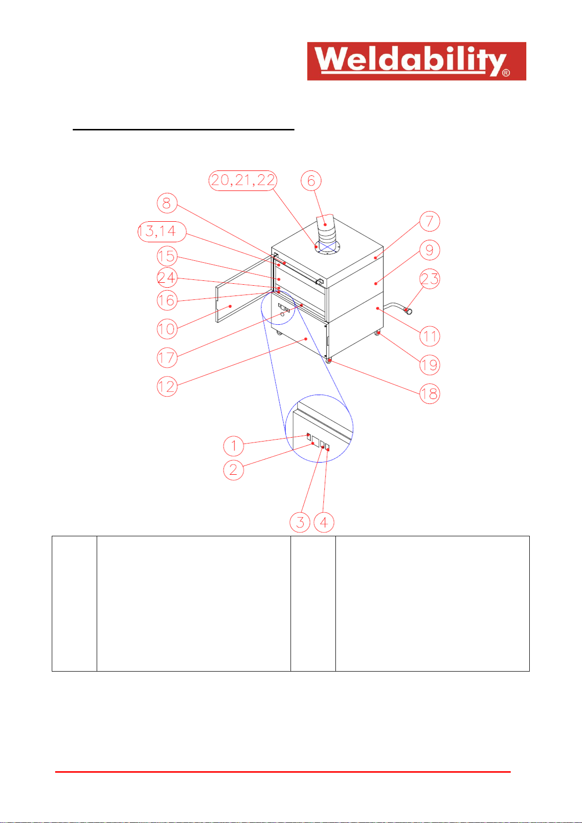
The pre-filter (Pos.14) must be changed at regular intervals. (Refer to chapter 7.1 ‘Changing of pre-filter
element’)
When the internal resistance of the filter element has increased due to the accumulation of the
separated dust particles and the extraction performance of the filter unit decreases as a whole, the
particle filter (Pos. 15) must be changed. (Refer to chapter 7.2 ‘Changing of particle filter element’)
As soon as odours appear the activated-carbon cassette (Pos.24) has to be changed.
Caution :
When changing the filter cartridge, the operation of the filter unit must be interrupted.
Exchange of the filter cartridge and the disposal of the element may be executed only in amply
ventilated environments and when using an appropriate protective respiratory mask.
We recommend to use a respiratory mask to DIN EN 141/143 - Protection class P3.
The job of changing the filter elements should be executed by trained personnel only. Filter disposal
according to pertinent directives on special waste handling.
Manually beating the filter element, washing or air jet blasting will destroy the filter media. As a result
the pollutants will be blown into the room.
7.1 Changing of pre-filter
The pre-filter mat (Pos.14) must be changed after a certain number of operating hours. The time
depends on the amount of accumulated dust. At the latest, the filter mat must be changed when
changing the particle filter.
The procedure is a follows:
•Disconnect the filter unit from the mains power supply.
•Open the air filter access door (Pos.10).
•Lower the lifting mechanism (Pos.16) by turning the lock screw (Pos.17) downward..
•Pull out the pre-filter tray (Pos.13).
•Take out the pre-filter mat (Pos.14).
•Install the new pre-filter mat.
Caution :
Only use original Weldability pre-filter elements.
•Insert the pre-filter tray (Pos.13).
Raise the lifting mechanism (Pos.16) by turning the locking screw (Pos.17) until the pre-filter
tray (Pos.13) sits tight. (At this time check the sealing gasket under the lid (Pos.7) for possible
damage.
•Close the filter access door (Pos.10).
•Connect the filter unit to the mains circuit.

ProtectoSmart - 10 -
7.2 Changing of particle filter
When the extraction performance decreases, the particle filter must be changed according to the
following procedure:
•Disconnect the filter unit from the mains power supply..
•Open the filter access door (Pos.10).
•Lower the lifting mechanism (Pos.16) by turning the locking screw (Pos.17) downward..
•Pull out the particle filter (Pos.15).
•Install the new particle filter element
Caution :
Only use original Weldability particle filter elements.
•Raise the lifting mechanism (Pos.16) by turning the locking screw (Pos.17) until the pre-filter
tray (Pos.13) sits tight. (At this time check the sealing gasket under the lid (Pos.7) for possible
damage.
•Close the filter access door (Pos.10).
•Connect the filter unit to the mains circuit.
7.3 Changing of the activated-carbon cassette
As soon as odours appear the activated-carbon cassette (Pos.24) has to be changed:
•Disconnect the filter unit from the mains power supply..
•Open the filter access door (Pos.10).
•Lower the lifting mechanism (Pos.16) by turning the locking screw (Pos.17) downward..
•Pull out the activated-carbon cassette (Pos.24).
•Install the new activated-carbon cassette.
Caution: Only use original Weldability particle filter elements!
•Raise the lifting mechanism (Pos.16) by turning the locking screw (Pos.17) until the pre-filter
tray (Pos.13) sits tight. (At this time check the sealing gasket under the lid (Pos.7) for possible
damage.
•Close the filter access door (Pos.10).
•Connect the filter unit to the mains circuit.

ProtectoSmart - 11 -
8 Disposal
To ensure perfect operation of your Weldability ProtectoSmart extractor unit and proper disposal of the
dust that has been extracted, we offer the following services:
•Help with finding a waste disposal company in your vicinity.
•On request, we can supply a list of all waste disposal companies in Germany, free of charge.
•A service and maintenance contract.
•A customer help line.
Call our service department for these options:
Telephone: +44 (0) 845 862 2620 Fax: +44 (0) 800 970 7757

ProtectoSmart - 12 -
9 Technical data
Filter unit
ProtectoSmart
Supply voltage
V
230
Current type
Ph
1
Frequency
Hz
50
Motor power
kW
1,1
Max. airflow volume
m³/h
2200
Max. vacuum
Pa
2500
Enclosure type
IP 54
ISO class
F
Operating voltage
V
24
Duty cycle
%
100
Width x depth x height
mm
665 x 681 x 1200
Weight, without arm
kg
95
Filter insert
pre filter, particle filter, activated-carbon
cassette
Filter performance
%
>99
Noise level
(measured as per DIN 45635 T1: in free air
at 1m distance from the surface of the machine,
max. airflow volume.
dB(A)
70
10 Parts list
Designation: Article no.
pre filter (Pos.14) 10032
particle filter H13 (Pos.15), 610x610x186 100357
activated-carbon cassette (Pos.24) 97053

ProtectoSmart - 13 -
11 Declaration of conformity Weldability - ProtectoSmart
Weldability sif
Peters House, The Orbital Centre
Icknield Way, Letchworth Garden City
Hertfordshire
SG6 1ET
Tel.: +44 (0) 845 862 2620 Fax: +44 (0) 800 970 7757
E-Mail: sales@weldability-sif.com www.weldability-sif.com
We herewith declare in sole responsibility that the before mentioned product, starting from machine No.:
10000010011001, conforms to the following standards:
Directives on machine building: 2006/42/EG
Electromagnetic compatibility: 2004/108/EG
Directives on printing device: 97/23/EG
Directives on low voltage: 2006/95/EG
Applied harmonised standards:
- DIN EN 349
- DIN EN ISO 4414
- DIN EN 12100: 2010
-DIN EN 60204 part 1
-DIN EN ISO 13857
-DIN EN ISO 14121
plus further national standards and specifications:
- DIN 45635 part 1
This declaration will become void if changes are effected to the suction and filter systems which were not
agreed upon in writing by the manufacturer.
Authorised representative for technical documentation: Technical department, Weldabiility
Table of contents
Popular Industrial Equipment manuals by other brands

ITEM
ITEM Linear Unit LRE 8 D14 80x40 KU 80 Notes on Use and Installation

INOXPA
INOXPA BFI Installation, service and maintenance instructions

Festo
Festo DG Series operating instructions

Armstrong
Armstrong TVS-5000 Series instructions

Siemens
Siemens PUMA V400/M Operation manual

Kitagawa
Kitagawa GT instruction manual

MaxVac
MaxVac DUSTBLOCKER 700 instruction manual

Bühler technologies
Bühler technologies GAS 222.11 Brief instructions

Lapeyre
Lapeyre Aluminum alternating tread stairs Assembly instructions

permaban
permaban AlphaJoint installation guide

Timken
Timken ROLLON ELM Series Use and maintenance

Nexen
Nexen AIR CHAMP FMCBE 110-14 user manual