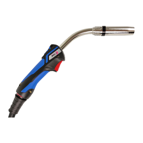
Weldclass Platinum PP365 User manual

Platinum PP365
PUSH PULL
Torch
User Manual

2
User Manual
Fumes and Gases
Fumes and gases emitted during welding may be dangerous, use
adequate ventilation and extraction equipment.
WARNING
Safety
Read Instructions
Before using this product, read the instructions and any related data
sheets. (See www.parweld.com).
Injury can occur from bodily contact with hot parts, sparks, fumes,
dust, noise and vibration.
welding screens.
Wear protective clothing to protect your body and ears.
Use adequate ventilation or wear respirator equipment to prevent
dust, fumes and gases from entering your lungs.
Electric Shock
Electric shocks can kill, use adequate protective equipment. Ensure a
safe earth connection. Do not touch electrical parts or electrode.
Arc Rays
Arc rays may burn eyes and skin. Wear protective clothing.
Burn and Fire Hazard
Weld and metal parts are hot and cause serious burn injuries if
materials from the welding area.

3
User Manual
Push Pull Torch Introduction
Function
The Push Pull MIG welding torch consists of a mechanical drive block that
incorporates a DC drive motor. This drives feed rolls that pull the welding wire push
fed from a wire feeding unit and power source, feeding it through a MIG welding
swan neck front end.
Swan Neck
Wire Feed Speed Control
Welding Torch Platinum PP365
Duty Cycle 270A @ 60% (Mixed Gas Ar+CO2)
Wires 0.8 - 1.6mm
Reference Torch Wire Feed Data
Nominal Wire
Feed Speed M/Min Ft/Min
Min 1.5 4.9 +/- 10%
Max 28.5 93.5 +/- 10%
Technical Data
The welding torch is supplied with a neck fitted. All necks are
fully rotatable through 360°.
Fine tuning of wire feed rates can be made via a speed control mounted
on the separate drive module. The drive module is fitted to the torch control input
lead. For more details see further informatin n this manual.

User Manual
4
Torch Maintenance
• At the neck root slacken the nut which secures the neck to the torch mount.
• release it.
• The neck liner and nipple combination will also need to be removed.
• The new neck will have a new neck liner and choice of nipples supplied, select
the nipple for the push pull torch.
• Fit the neck liner and nipple into the neck. trim the liner material if necessary to
correct the length as detailed below.
• Fit both the neck and neck liner into the torch neck mount.
• Tighten the neck nut. If a swan neck, before fully tightened position the neck in
the orientation required. Then fully tighten the nut to secure.
Neck Fitting
Disconnect the torch from the power supply so that it can not be
triggered accidentally.
Neck Liner
Neck Liner
Nipple

User Manual
5
Nozzle and Front End Consumables
Remove the nozzle from the front of the neck. Remove all spatter from
short circuit. Check all front end consumables for damage and wear.
Replace with new if necessary.
To maintain the best performance repeatedly check and clean the front end
consumables periodically. Also use an anti spatter spray on the consumables to
reduce the build up of debris.
Torch Feed Unit
Open the torch feed unit hatch and inspect. Wire scale debris will build
up inside the torch around the feed unit mechanism. Regularly clean
out the torch feed unit using an air blow gun to blow out this debris.
To maintain the best operation of the torches feed mechanism clean
out the debris daily before use at the very least.
Keep gas holes
clear of spatter and
debris

User Manual
6
Feed Rolls
The feed rolls will wear over time. Check the roll grooves for wear
and debris. Debris can be removed with a wire brush. If the groove is
excessively worn, replace.
To change the feed rolls;
• both the pressure roll and the feed roll.
• The drive roll has a retaining cap to lock the roll to the drive shaft. This will lift
• drive to lever them if they are tight.
• Replace the rolls with the required size.
• shaft mount.
•
• Secure both rolls with the screws, tightening with a screw driver.
Screws
Retaining Cap
Pressure Roll
Drive Roll

User Manual
7
Neck Wire Inlet Guide
The neck guide will wear as the wire is fed through into the neck. To
maintain trouble free wire feeding periodically check and renew this
guide.
Liner Fitting
•
• Remove the liner retaining nut from the gun plug body liner stem.
• Remove the old liner by pulling it out of the stem.
• Feed the new liner into the gun plug liner stem. Push up the torch until it hits the
guide in the torch handle. The liner should be visible through the inspection hole
of the guide.
• retaining nut over the nipple.
•
To remove the guide;
• Remove the retaining screw using a hexagonal key. 2mm A/F.
• Lift the guide out of its location. Removing the feed rolls will make this easier.
• There is a renewable liner inner that can be replaced. Remove the gas seal O
ring and then withdraw the guide liner.
•
• Return the guide assembly into the drive unit location ensuring the O ring and
liner tube locate correctly. Secure using the retaining screw.
Neck
Guide
O Ring
Liner Inner
Guide Body
Screw

User Manual
8
Roll Pressure
Before changing the feed rolls or feeding the wire through the torch
the pressure on the pressure roll must be reduced.
• First check to see if there is any pressure on the pressure roll by
opening the feed unit hatch and pulling on the release arm. If there
pressure roll move.
• the torch anti-clockwise. Turn two or three times and check the pressure release
lever again. If the feed roll moves away from the drive roll easily then enough
Torch Set Up
Adjustment Knob
Release Lever
Pressure
Roll

User Manual
9
Wire Feed Set Up
Setup the wire in the power source feed unit ready to be fed through
the torch. If the wire has a strong cast, feeding can be improved by
adding a slight bend in the end of the wire to straighten it, before clamping in the
feed rolls.
To feed the wire through the torch;
• Turn on the power source.
• Press the torch trigger. This should start the power source feed unit drive and
the torch feed unit drive simultaneously.
• The wire will fed up through the torch. Use the speed control of the power
source wire feed unit to vary the wire feed speed, slowing the wire as it reaches
the end of the torch.
• As the wire feeds into the torch feed unit have the rolls in the open position by
pulling on the roll pressure release lever, which should be adjusted to a low
pressure load.
• When the wire passes between the rolls release the trigger to stop the drive.
• Release the lever to close the rolls together. You may need to push the wire
• Operate the torch trigger again to fed the wire into the neck guide and through
the neck.
• When the wire is visible from the end of the contact tip release the trigger to
stop the wire feeding.

User Manual
10
Roll Pressure Adjustment
Before welding the pressure roll will need to be tightened against the
wire sat in the groove of the two feed rolls.
To adjust;
• Turn the pressure adjustment knob on the side of the torch in
the clockwise direction. Turn one, two or three times to load up the
pressure on the rolls.
• If during welding the rolls appear to be loosing grip on the wire, add more
pressure to the rolls by additional clockwise turns on the adjustment knob.
Do not over tighten as this may damage the wire and cause excessive debris build
up in the drive unit.
Identifying drive balance condition:
With the pressure roll slackened off , watch the torch pull drive roll rpm relative to
the wire feed speed.
If the wire is moving faster
than the roll rotates, this is an
“Under” speed condition which
may lead to the wire tangling
and nesting at the back of the
rolls.
If the wire is moving slower
than the roll rotates, this is
an “Over” speed condition
leading to wire stretching and
excessive debris build up in
the drive chamber.
The ideal condition is a slight
over speed condition. Enough
speed to pull on the wire but
not too much that the rolls skid
excessively over the wire and wearing.
User Manual
11
Initial Drive Speed Balancing
To correct the pull torch drive speed the adjustment is made on the
control lead in-line voltage drive module.
Trimming drive module to balance speed:
Locate the adjustment trimmer screw access port found on the body of
the drive enclosure, see image below.
port and reaches the white slotted trimmer screw.
Turn the trimmer screw slightly in the direction to suit the speed adjustment
required.
Over speed :
Turn the screw slightly counter-clockwise to reduce speed.
Under speed :
Turn the screw slightly clockwise to increase speed.
Warning:
Do not make large adjustment as this may cause an over voltage condition that will
damage the torch drive motor.
Test the adjusted speed by operating the torch and assessing the wire feed ratio to
the drive roll rotation.

User Manual
12
Trouble Shooting
Wire feeding erratic Roll pressure is too low, adjust the
pressure by tightening the adjustment
knob on the side of the torch.
Torch feed rolls may be worn or the
the feed roll condition and replace if
necessary.
Torch drive roll rotates counter-
clockwise, against the direction of wire
feeding.
Drive motor power supply is connected
in reverse polarity. Open the torch
gun plug housing and swap the wire
connections for the drive motor. The
“Red” and “Black” leads.
Problem Remedy
Wire feeder does not activate when
torch trigger is operated Check and secure torch gun plug
connection with the feeding machine
Check torch trigger is operating and
connection is made through the torch
Check feeding machine via the users
manual
Wire feeder activates when torch trigger
is operated but torch drive does not
feed
Check and secure the control lead
connection with the drive module
Check the input voltage and drive signal
lead connection are made to the correct
terminals in the source feeder machine.
Check the speed control selector switch
is in the correct position for the torch
Adjust the speed control trimmer,
either on the drive module or the torch
Torch drive speed running at maximum
when the trigger is operated, speed
adjusted
Torch control lead wires may be
connected incorrectly.
Torch drive is not running when the
trigger is operated, speed trimmer is not Torch control lead wires may be
connected incorrectly.
when adjusted
Check the connections as secure
through the torch and with the control
lead to the drive module
Wire “birds nests” in torch feed unit
behind the feed rolls Pull drive speed is too slow. Adjust the
speed using the local or remote controls
depending on torch set up.
Excessive debris build up in torch drive
unit Pull drive speed is too fast, slipping
on the wire and abrading the wire
surface. Adjust the pull feed speed
using the local or remote speed controls
depending on torch set up.
Table of contents