1.1 Introduction
We appreciate your business and your choice of Welker products. The installation, operation, and maintenance liability for this
equipment becomes that of the purchaser at the time of receipt. Reading the applicable Installation, Operation, and
Maintenance (IOM) Manuals prior to installation and operation of this equipment is required for a full understanding of its
application and performance prior to use.*
If you have any questions, please call Welker at 1-281-491-2331.
*The following procedures have been written for use with standard Welker parts and equipment. Assemblies that have been modified may have additional
requirements and specifications that are not listed in this manual.
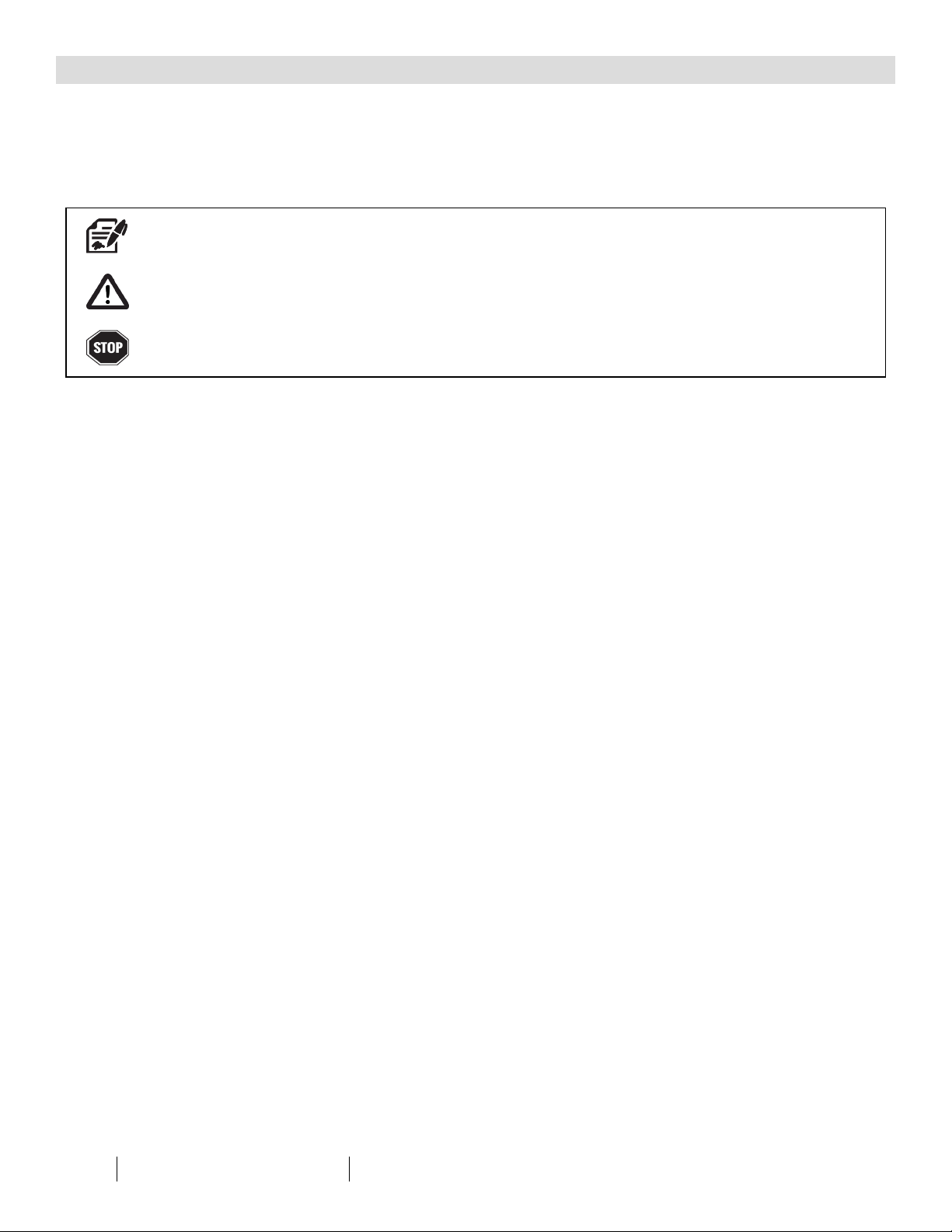
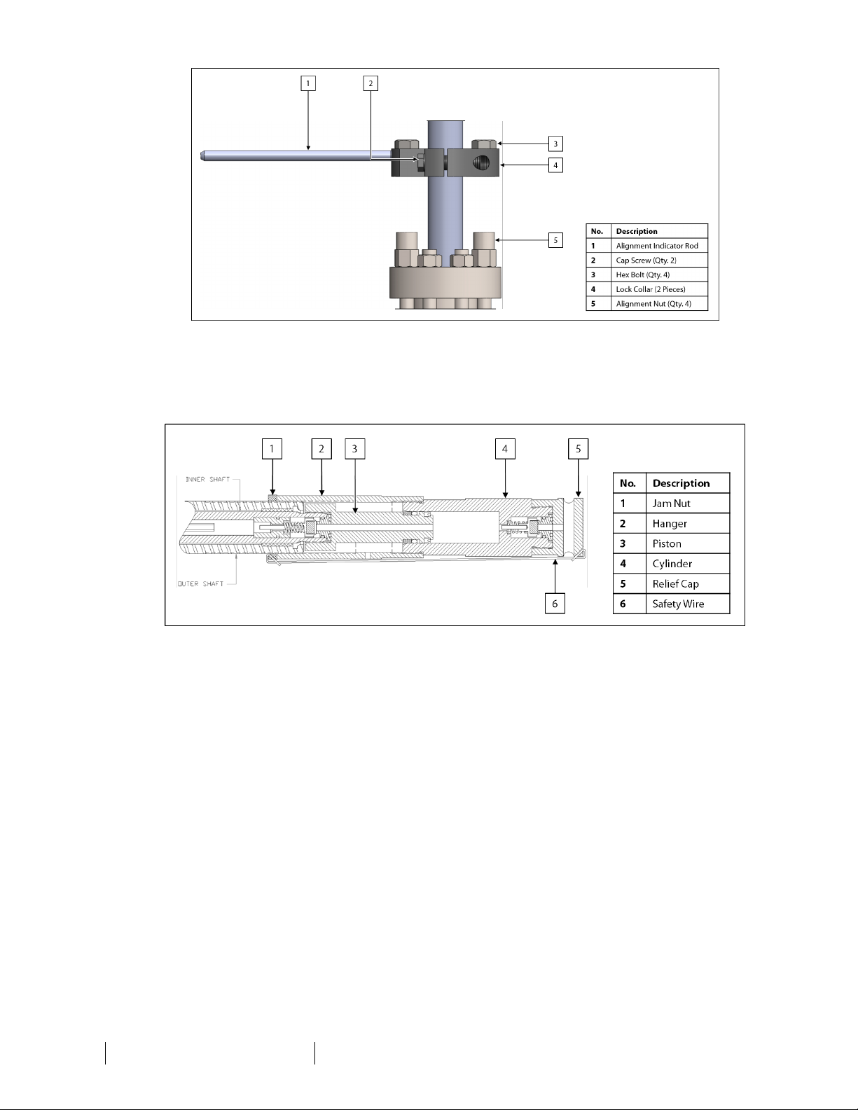
1.2 Product Description
The Welker inFlow™ ACE Crude OilSampler is an isokinetic probe sampler designed to extract a representative sample of liquid
product from the flowing stream. When used with a pipeline isolation valve, the inFlow™ ACE with AI Control™ can be safely
inserted and retracted without interfering with or venting pipeline pressure. Once all desired samples have been collected, the
inFlow™ ACE can be fully evacuated of internal sample volume using the purge tube, thus preparing the sampler for the next
sample batch.
The operator controls the insertion and retraction of the probe by manipulating valves and applying process or auxiliary pressure.
The inFlow™ ACE features an adjustable insertion length to accommodate different pipeline sizes. Sampling may be hydraulically
or pneumatically operated but is electronically controlled from a Programmable Logic Controller (PLC) or other signal control
system. Sampling may be timed or proportional to flow.
With protection from an external sand relief and check valves designed for sandy oils, this sampler is capable of sampling
product containing sand or debris. For added safety, the inFlow™ ACE is equipped with a dustcover, shaft wipers to protect seals,
and an adjustable V-ring packing for emergency shutdown leak protection.
Designed with ease of use in mind, the external sample volume adjustment simplifies operation of the inFlow™ ACE even further.
The external adjustment allows the operator to adjust the sample volume without having to remove the inFlow™ ACE from the
pipeline.
For this manual, the term "PLC," or Programmable Logic Controller, will be used to refer to the PLC, DCS, or other signal control
system used by the customer to activate and operate the solenoid.
Welker may custom design the inFlow™ ACE to suit the particular application and specifications of each customer.
SECTION 1: PRODUCTINFORMATION
4IOM-161 MODEL: INFLOW™ ACE WITHAICONTROL™ REV: D 13839 West Bellfort Street, Sugar Land, TX 77498 welker.com Service Department 281.491.2331