Wellav CMP201D User manual

CMP201D
Media Platform
User Guide
V1. 5-W

CMP201D User Guide
i
Revision History
Date
Version
Description
Author
25/12/2018
1.0
First Draft
SW
25/4/2019
1.1
Add new modules and new features
DA
5/6/2019
1.2
Add new modules and modify the baseboard description
CJ
9/7/2019
1.3
Add new modules and new features
SW
14/11/2019
1.4
Add module CP-CAM-00
MC
28/12/2019
1.5
Add EAS parts for relevant encoding modules
CJ
31/8/2020
1.6
Modify the pictures and content according to V1.4.0. Add Module
CR2-DVBS2FTA-01, CE2-HDMI-06, CM2-MOD-02, CP2-EIT-00
JP
This guide contains some symbols to call your attention.
DANGER
The DANGER symbol calls your attention to a situation that, if ignored, may cause
physical harm to the user.
CAUTION
The CAUTION symbol calls your attention to a situation that, if ignored, may cause
damage to Our product.
NOTE
The NOTE symbol calls your attention to important information.
TIP
The TIP symbol calls your attention to additional information that, if followed, can
make procedures more efficient.
Red Arrow
The Red Arrow symbols point to import details mention the context above or below
an image.
Blue Arrow
The Blue Arrow symbol indicates the motion path of an item in an operation step.
Thick Arrow
The thick Arrow symbol calls your attention to a series of operation steps mentioned
in the context.
This guide also contains the following text conventions.
Bold Italic
The bold Italic text indicates a button to click, an item in the drop-down menu to
select, or a certain item in the UI.

CMP201D User Guide
ii
Safety Instructions
Read these instructions
Keep these instructions
Follow all instructions
Heed all warnings
Do not use this unit near water.
Only use a damp cloth to clean chassis
Do not install near any heat sources such as radiators, heat registers, stoves, or other
apparatus (including amplifiers) that produce heat
Do not block any ventilation openings. Install in accordance with the manufacturer’s
instructions
This unit is grounded through the power cord grounding conductor. To avoid electrocution, do
not remove the power cord before the outlet is switched off or unplugged. If the plug does not
fit into your outlet, consult an electrician for replacement of the outlet.
Route power cords and other cables so that they are not likely to be damaged.
Only use attachments/accessories specified by the manufacturer.
Do not wear hand jewelry or watch when troubleshooting high current circuits.
Do not work on the system during periods of lightning.
Refer all servicing to qualified service personnel. Servicing is required when this unit has
been damaged in any way.
Damage Requiring Service: Unplug this product from the wall outlet and refer servicing to
qualified service personnel under the following conditions:
When the power-supply cord or plug is damaged.
If liquid has been spilled, or objects have fallen into the product.
If the product has been exposed to rain or water.
If the product does not operate normally by following the operating
instructions. Adjust only those controls that are covered by the operating
instructions as an improper adjustment of the controls may result in
damage and will often require extensive work by a qualified technician to
restore the product to its normal operation.
If the product has been damaged in any way.
Replacement Parts: When replacement parts are required, be sure the service technician
uses replacement parts specified by the manufacturer. Unauthorized part substitutions made
may result in fire, electric shock or other hazards.

CMP201D User Guide
1
Contents
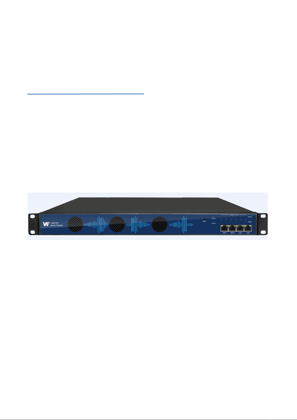
1 Chassis Overview........................................................................................................................................... 3
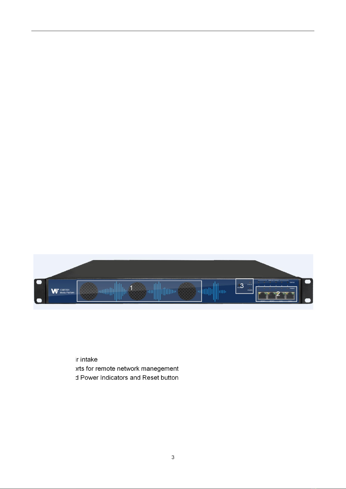
1.1 Front Panel........................................................................................................................................... 3
1.2 Back Panel............................................................................................................................................4
2 Installation........................................................................................................................................................ 5
2.1 Rack Installation.................................................................................................................................. 5
2.2 AC Power Connection........................................................................................................................ 5
3 Module Overview............................................................................................................................................ 7
3.1 CM2P201 Baseboard..........................................................................................................................7
3.2 ReceiverModules.................................................................................................................................7
3.3 Encoder Modules.................................................................................................................................7
3.4 Modulator Modules..............................................................................................................................9
4 Web GUI........................................................................................................................................................ 11
4.1 Web GUI Overview........................................................................................................................... 11
4.1.1 Connect the Management Port............................................................................................11
4.1.2 Login to the Web GUI............................................................................................................12
4.2 Status.................................................................................................................................................. 12
4.3 System Setting...................................................................................................................................13
4.4IP Input.................................................................................................................................................16
4.5 IP output..............................................................................................................................................20
4.6 Admin.................................................................................................................................................. 23
5 Module Configuration................................................................................................... 错误!未定义书签。
5.1 Receiver Modules..............................................................................................错误!未定义书签。
5 Module Configuration.................................................................................................................................. 24
5.1 Receiver Modules..............................................................................................................................24
5.1.1CR2-DVBC-00......................................................................................................................... 24
5.1.2 CR2-DVBS2CI-00.................................................................................................................. 28
5.1.3 CR2-DVBS2FTA-00/00A...................................................................................................... 29
5.1.4 CR2-DVBS2FTA-01.............................................................................................................. 30
5.1.5 CR2-8VSB-00.........................................................................................................................38
5.1.5 CR2-DVBT2-00...................................................................................................................... 39
5.2 Encoder Modules.............................................................................................................................. 40
5.2.1 CE2-HDMI-00/R01.................................................................................................................40
5.2.2 CE2-HDMI-02......................................................................................................................... 49
5.2.4 CE2-SDI-00.............................................................................................................................58
5.2.5 CE2-CVBS-00/R01/R01A.....................................................................................................62
5.2.6 CE2-HDMI-05/05A.................................................................................................................66
5.2.7 CE2-HDMI-06......................................................................................................................... 73
5.3 Modulation Output modules.............................................................................................................80
5.3.1 CM2-QAMA-R00/R01/R01A................................................................................................ 80
5.3.2 CM2-8VSB-R01/R01A.......................................................................................................... 85
5.3.3 CM2-QAMB-R00/R01/R01A................................................................................................ 86
5.3.4 CM2-OFDM-R01/R01A.........................................................................................................90

CMP201D User Guide
2
5.3.5CM2-ISDBT-R01/R01A.......................................................................................................... 92
5.3.6 CM2-MOD-02......................................................................................................................... 94
5.4 Function modules............................................................................................................................112
5.4.1 CP2-EAS-00......................................................................................................................... 112
5.4.2 CP2-CAM-00........................................................................................................................ 115
5.4.3 CP2-EIT-00...........................................................................................................................121
6 Appendices..................................................................................................................................................126
Appendix A – Abbreviations.................................................................................................................126
Appendix B- Warranty...........................................................................................................................128
Appendix C- After-Sales Support........................................................................................................ 128

CMP201D User Guide
3
1 Chassis Overview
1.1 Front Panel
CMP201D is a new generation of compact media platform which focuses on cost-effective
commercial TV market and traditional DTV market.
With powerful embedded Gigabit switch, optional commercial/broadcast level encoder modules and
multi-mode receiver and modulator modules, it has been preconfigured to meet all the major video
delivery requirements of signal receiving, descrambling, encoding, multiplexing, modulation and IP
processing depending on a variety of models.
Due to its compact design, powerful functions, super practical price and low operational cost, it’s a
perfect choice for commercial video delivery applications for hotel, campus, hospital, MDU and more
kinds of cable TV and IPTV systems, where massive programs are required to be processed, saving
you more space and expense.
1. Cooling air intake
2. 4 RJ45 ports for remote network manegement
3. Status and Power Indicators and Reset button

CMP201D User Guide
4
1.2 Back Panel
CMP201D
I. 6 hot-swappable modules
II. Dual Power Supply
III. Ground

CMP201D User Guide
5
2 Installation
2.1 Rack Installation
The CMP201D is designed to be mounted in a standard 19” rack. It takes 1RU of rack space. To
install it into a rack, please use the following steps:
1. Determine the desired position in the rack for the CMP201D. Make sure that the air intake
on the top of the unit and the exhausts on the back of the unit will not be blocked.
2. Install the brackets at desired position if there’s no supporting plate in the rack.
3. Insert the rack mount clips into place over the mounting holes in the rack.
4. Slide the CMP201D into the position in the rack.
5. Secure the chassis to the rack by installing the four supplied screws through the front
mounting holes and tightening.
2.2 AC Power Connection
Please only use the supplied 3-prong power connector or one with equal specifications. NEVER
tamper with or remove the grounding pin. This could cause damage to CMP201D, personnel, or
property. Make sure the power outlet is switched off before plug or unplug the power cable from the
panel of CMP201D.

CMP201D User Guide
6
When you take the equipment from a cold condition into a much warmer and humid c
ondition, the equipment should be acclimated to the warm and humidity condition for at least
30 minutes. Powering up a non-acclimated unit may lead to shortcut or other damage to ele
ctronic components.
A professional UPS system is recommended for better performance of your content distri
bution system.

CMP201D User Guide
7
3 Module Overview
3.1 CMP201D Baseboard
CMP201D
Basic Function
Baseboard
120 inputs & 120 outputs IP channel
3.2 Receiver Modules
Module
Description
CR2-DVBC-00
4-channel DVBC receiving and descrambling
module with 1 RF female connector and 2 CI slots
CR2-DVBS2CI-00
4-channel DVB-S/S2 receiving and descrambling
module with 2 RF connectors and 2 CI slots
CR2-DVBS2FTA-00/00A
4/8-channel DVB-S/S2 receiving module with 4/8
RF connectors
CR2-DVBS2FTA-01
4-channel DVB-S/S2/S2XFTA receiving module
with 4 RF connectors
CR2-8VSB-00
4-channel 8VSB receiving module with 4 RF
connectors
CR2-DVBT2CI-00
4-channel DVB-T/T2 receiving and descrambling
module with1 RF connectors and 2 CI slots
3.3 Encoder Modules
Module
Description
CE2-HDMI-00
CE2-HDMI-R01
4-channel HDMI HD encoder (broadcast level),
supports H.264 HD/SD, MPEG-2 SD, MPEG1L2,
AAC, AC3
4-channel HDMI HD encoder(commercial grade),
supports H.264 HD/SD, MPEG1L2, AAC (optional),
AC3 (optional), supports overlay OSD subtitles,
station logo, two-dimensional code, does not
support interlaced video signals input

CMP201D User Guide
8
CE2-HDMI-02
CE2-HDMI-02C
2-channel HDMI HD encoder, supports H.
264/MPEG-2 HD/SD, MPEG1L2, AAC (optional),
AC3 (optional), supports CC subtitles
2-channel HDMI or component HD encoder,
supports H.264 / MPEG-2 HD/SD, MPEG1L2, AAC
(optional), AC3 (optional), support CC subtitle and
analog audio input
CE2-CVBS-00
CE2-CVBS-R01
CE2-CVBS-R01A
6-channel CVBS encoding module, supports
H.264/MPEG-2 SD, MPEG1L2,(professional chip)
8-channel CVBS encoding module, supports H.264
SD, MPEG1L2, AAC (optional), AC3 (optional)
(commercial chip)
16-channel CVBS encoding module,supports H.264
SD, MPEG1L2, AAC (optional), AC3 (optional)
(commercial chip)
CE2-SDI-00
2-channel SDI HD encoder, supports H.264 /
MPEG-2 HD/SD, MPEG1L2,AAC (optional), AC3
(optional), supports CC subtitle and analog audio
input
CE2-HDMI-05/05A
4/8-channel HDMI input encoder, supports
H.264/H.265 HD/SD encoding, supports
MPEG1-L2, AAC (optional) and AC3 (optional)
audio encoding.Also supports overlay OSD
subtitles, station logo and QR code
CE2-HDMI-06
4-channel HDMI encoder (broadcast level),
supports H.264/H.265 HD/SD encoding (up to
1080p60), B frame and de-interlacing. supports
MPEG1-L2, AAC (optional) and AC3 (optional)
audio encoding.Also supports QR code, logo,
subtitles insertion

CMP201D User Guide
9
3.4 Modulator Modules
Module
Description
CM2-QAMA-R00
CM2-QAMA-R01 / R01A
supports modulating 16 non-adjacent or channels
with 1 RF female port for modulating output and 1
RJ45 network port is reserved for future use.
supports modulating 4/8 adjacent channels with 1
RF female port for modulating output.
CM2-ATSC-R01/R01A
supports 4/8 adjacent frequencies modulating with
1 RF female connector for output.
CM2-QAMB-R00
CM2-QAMB-R01 / R01A
supports up to 16non-adjacent frequencies
modulating with 1 RF female connector for output
supports up to 4/8 adjacent frequencies
modulating with 1 RF female connector for output
CM2-OFDM-R01 / R01A
supports up to 4/8 adjacent frequencies
modulating with 1 RF female connector for output
CM2-ISDBT-R01/ R01A
supports up to 4/8 adjacent frequencies
modulating with 1 RF female connector for output
CM2-MOD-02
32-channel QAM-A modulation output module with
2 gigabit IP input ports, single port supports
512-channel input; 1 CAS interface (RJ45),
supports scrambling function; 1 RF output
interface, supports up to 32 QAM-A non-adjacent
frequencies modulating with independent
constellation mode configuration.

CMP201D User Guide
10
3.5 Function Modules
Module
Description
CP2-EAS-00
supports EAS triggerring by analogue EAS input
and digital EAS input
CP2-CAM-00
scrambling & descrambling module with 2 CI slots.
It supports almost all kinds of CAM card
descrambling and the number of descrambled
services is defined by the CAM card. It supports
descrambling services which are multiplexed from
different IP/RF channels or modules.
CP2-EIT-00
EIT multiplex module.Supports up to 32 TS inputs
and up to 16 TS outputs. It also supports EIT
multiplexing enable control at module level, TS level
and program level. Multiple EIT multiplexing
modules can run simultaneously in a single chassis

CMP201D User Guide
11
4 Web GUI
4.1 Web GUI Overview
4.1.1 Connect the Management Port
Factory network settings of the Management Port:
IP address 192.168.1.10
Subnet Mask 255.255.255.0
Gateway 192.168.1.254
Take the following steps to access the Web GUI in a browser.
Connect laptop/computer to CMP201D management port directly.
Set the IP address of the laptop/computer in the same network segment with the CMP201D
Baseboard. CMP201D will occupy up to 7 IP addresses if it’s fully loaded as each module has its
own IP address including the baseboard. Please avoid possible IP address conflict between
management PC and CMP201D unit.
Check the physical connection by ping command.

CMP201D User Guide
12
CMP201D has an embedded gigabit switch inside the chassis. You can use it as a switch with
other devices together. The four network ports are respectively used for managing and streaming.
From left to right, port 1 and port 2 are used for management, port 3 and port 4 are used for data
transmission.A good method of checking IP output is to play the IP streams using VLC player
directly.
If you want to connect a switch between CMP201D and PC or other devices, this switch should
support IGMP V2 and IGMP snooping function. If the switch you used is not configured properly, it
could cause some network issue.
4.1.2 Logging into the Web GUI
Enter the CMP201D Baseboard IP address into the URL field of any recommended Web browsers
(IE8 or above, Firefox, and Google Chrome) to access the login page. The default user name and
password are both admin. Click Login to log into the GUI.
4.2 Status
Status>Device status
After a successful login, you will always enter the status overview page, where you can check the
device status of:
a) Module List: it shows the module(s) inserted

CMP201D User Guide
13
b) Device host operating status, running status of fans and other status display options
c) Menu Bar and time display
We use only IE, Firefox and Chrome for testing procedures. If you use other browsers, like
Microsoft Edge, you may encounter incomplete UI layouts, and configure setting in these browsers
may lead to errors.
Status>Device Information
Device Information page shows the firmware version, software version, and hardware version of
baseboard and each inserted module.
4.3 System Setting
Click the System Setting on the top right corner to enter the system setting page where you can find
Network, Time Setting, System Manage and Password.
c)
b)
a)

CMP201D User Guide
14
System Setting> Network
In Network page you can assign a static IP address to CMP201D’s baseboard. Click the Apply
button on the right side to make the change take effect.
Note to avoid IP conflict when you set the baseboard IP address. The occupied IP section will be
displayed in this page on the top blue area.
System Setting> Time
In Time page you can see the current system time, change Time Zone, choose system time Mode
(Manual or Automatic), enable/disable Auto Sync and modify NTP Server Address in Automatic
mode or change the current system Time in Manual mode. Click the Apply button on the right side to
make the change take effect.
Automatic mode
Manual mode

CMP201D User Guide
15
System Setting>System
In System page you can do an upgrade, import or export configuration, import or export license (only
for baseboard), reboot the whole unit, restore it to factory setting (only for baseboard), export log and
clear log (only for baseboard).
System Setting> Password
In Password page you can reset login password.

CMP201D User Guide
16
4.4 IP Input
Click the IP Input on the top line to go into IP input page where you can see Status, Basic Setting
and Service Configuration.
IP Input >Status
In this page, you can check each channel Total Bit Rate, Effect Bit Rate, TS Analysis and Service
List.
Click the icon ( ) in the TS Analysis list to see the TS analyzing result of this channel. Click the
icon ( ) in the Service List to see the Services of each channel.
TS Analysis

CMP201D User Guide
17
Click Reset Counter button to clear continuity count errors and restart counting. Fill in the search bar
with the key words of PID / Bit rate / bandwidth / table type / service name in the search bar to get the
info you want.
Service List
Click a service name to check the detailed info of this service.
IP Input >Settings
Here you can configure IP input parameters: Source IP Address,Source Port,Protocol
(UDP/RTP), TS Packets Per IP Packet ,VLAN Enable, and TSIP Port. Click Apply to make the
setting take effect.
This manual suits for next models
1
Table of contents