Wenger Showmobile Mobile Stage and Canopy User manual
Introduction
Important User Information � � � � � � � � � � � � � � � � � � � � � � � � � � � � � � 2
Safety Precautions � � � � � � � � � � � � � � � � � � � � � � � � � � � � � � � � � � � � 3
Specications � � � � � � � � � � � � � � � � � � � � � � � � � � � � � � � � � � � � � � � � 6
Setup
Towing the Showmobile� � � � � � � � � � � � � � � � � � � � � � � � � � � � � � � � � 8
Selecting a Location � � � � � � � � � � � � � � � � � � � � � � � � � � � � � � � � � � � 9
Disconnecting the Towing Vehicle� � � � � � � � � � � � � � � � � � � � � � � � � 9
Leveling the Showmobile � � � � � � � � � � � � � � � � � � � � � � � � � � � � � � � 10
Connecting Auxiliary Power� � � � � � � � � � � � � � � � � � � � � � � � � � � � � � 13
Opening the End Panels � � � � � � � � � � � � � � � � � � � � � � � � � � � � � � � � 14
Opening the Roof/Canopy� � � � � � � � � � � � � � � � � � � � � � � � � � � � � � � 15
Lowering and Leveling the Hydraulic Stage � � � � � � � � � � � � � � � � � 16
Raising the Roof/Canopy � � � � � � � � � � � � � � � � � � � � � � � � � � � � � � � 17
Attaching Additional Stage Units � � � � � � � � � � � � � � � � � � � � � � � � � � 18
Attaching Stairways� � � � � � � � � � � � � � � � � � � � � � � � � � � � � � � � � � � � 20
Attaching Accessories � � � � � � � � � � � � � � � � � � � � � � � � � � � � � � � � � � 20
Optional Lighting Packages� � � � � � � � � � � � � � � � � � � � � � � � � � � � � � 21
Positioning the End Panels � � � � � � � � � � � � � � � � � � � � � � � � � � � � � � 24
Shutdown
Closing with Stage in the Performance Position� � � � � � � � � � � � � � 25
Closing the Showmobile for Travel � � � � � � � � � � � � � � � � � � � � � � � � 26
Maintenance� � � � � � � � � � � � � � � � � � � � � � � � � � � � � � � � � � � � � � � � � 28
Electrical Schematic � � � � � � � � � � � � � � � � � � � � � � � � � � � � � � � � � � 31
12V Wiring Diagram � � � � � � � � � � � � � � � � � � � � � � � � � � � � � � � � � � 34
Hydraulic Schematic � � � � � � � � � � � � � � � � � � � � � � � � � � � � � � � � � � 35
Troubleshooting � � � � � � � � � � � � � � � � � � � � � � � � � � � � � � � � � � � � � 36
Owner's Manual
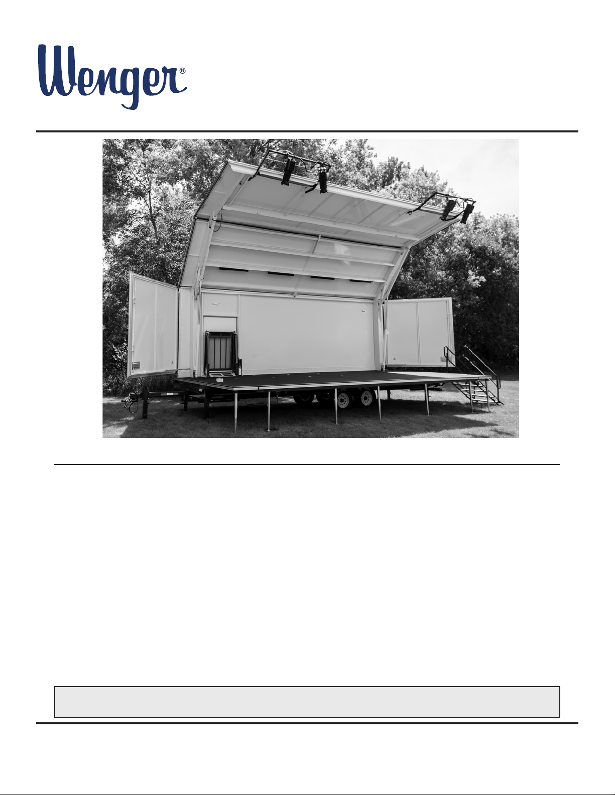
Showmobile
®
Mobile Stage and Canopy
©Wenger Corporation 2020 Printed in USA 2020-11 Part #089F049-04
Wenger Corporation, 555 Park Drive, P�O� Box 448, Owatonna, Minnesota 55060-0448
USA: (800) 4WENGER (493-6437) • Worldwide: +1-507-455-4100 • wengercorp�com
Contents
Note: Please read and understand these instructions before operating�
Note: If you need additional information, contact Wenger Corporation using the information below�
Visit the Showmobile Mobile Stage and Canopy web page at wengercorp.com for more information.

2
Important User Information
General
Copyright © 2020 by Wenger Corporation
All rights reserved� No part of the contents of this manual may be reproduced, copied, or transmitted in any form or
by any means including graphic, electronic, or mechanical methods or photocopying, recording, or information storage
and retrieval systems without the written permission of the publisher, unless it is for the purchaser's personal use�
Printed and bound in the United States of America�
The information in this manual is subject to change without notice and does not represent a commitment on the part of
Wenger Corporation� Wenger Corporation does not assume any responsibility for any errors that may appear in these
instructions�
In no event will Wenger Corporation be liable for technical or editorial omissions made herein, nor for direct, indirect,
special, incidental, or consequential damages resulting from the use or defect of these instructions�
The manufacturer reserves the right to change this product at any time�
The information in this document is not intended to cover all possible conditions and situations that might occur� The
end user must exercise caution and common sense when assembling or installing Wenger Corporation products� If any
questions or problems arise, call the Wenger Corporation at (800) 4WENGER (493-6437)
or +1-507-455-4100 worldwide�
Manufacturer
The Showmobile®Mobile Stage and Canopy is manufactured by:
Wenger Corporation
555 Park Drive
Owatonna, MN 55060
(800) 4WENGER (493-6437) • +1 (507) 455-4100
wengercorp�com
Warranty
This product is guaranteed free of defects in materials and workmanship for ve full years from date of shipment.
A full warranty statement is available upon request�
Setup and Operation
Use only authorized and trained personnel to set up
and take down the Showmobile� Insist that those who
handle the unit be familiar with these instructions�
Never raise or lower the roof/canopy while people are
under it or inside the Showmobile� Keep bystanders
away until the roof/canopy and hydraulic stage are set
up and fully secured�
After setup, never leave the hydraulic stage and roof/
canopy open when the Showmobile is unattended�
Never move the Showmobile with the roof/canopy in
the raised position, as the unit will be top-heavy�
Use only experienced, competent drivers, be extra
careful when turning, and be conservative when
accelerating and braking�
Wind Precautions
Because of the large surface area of the roof/canopy,
heavy winds can tip the Showmobile� If the wind
raises (or threatens to rise) above 30 mph, remove all
personnel and lower the roof/canopy�
Electrical Power
If the standard auxiliary power cord cannot be used,
Wenger recommends that a licensed electrician make
the necessary connections between the Showmobile
and the auxiliary power source or, if appropriate,
provide you with a cord and standard plug suitable for
use with your local electrical system�
Battery
Batteries normally produce explosive gases which can
cause personal injury. Therefore, do not allow ames,
sparks, or lighted tobacco products to come near the
battery� When charging or working near a battery,
always shield your face and protect your eyes� Always
provide ventilation around the battery�
Do not charge or use booster cables, or adjust post
connections, without proper training�
Keep batteries out of reach of children� Batteries
contain sulfuric acid� Avoid contact with skin, eyes,
or clothing� Shield your eyes when working near the
battery to protect against possible splashing of the
acid solution� In case of acid contact with skin or eyes,
ush immediately with water for at least 15 minutes
and get prompt medical attention� If acid is swallowed,
call a physician immediately�
Keep vent caps tight and level� When lifting a plastic-
cased battery, excessive pressure on the end walls
(for instance, if the battery is dropped) could cause
acid to spew through the vent caps, resulting in
personal injury� Always lift with a battery carrier or with
your hands on opposite corners�
3
Make sure that anyone working
with the Showmobile has
read and understands these
instructions.
Always observe and comply
with the Warnings and
Cautions posted on the system
equipment.
Failure to comply with Warnings
and Cautions in this document
can result in damage to property
or serious injury.
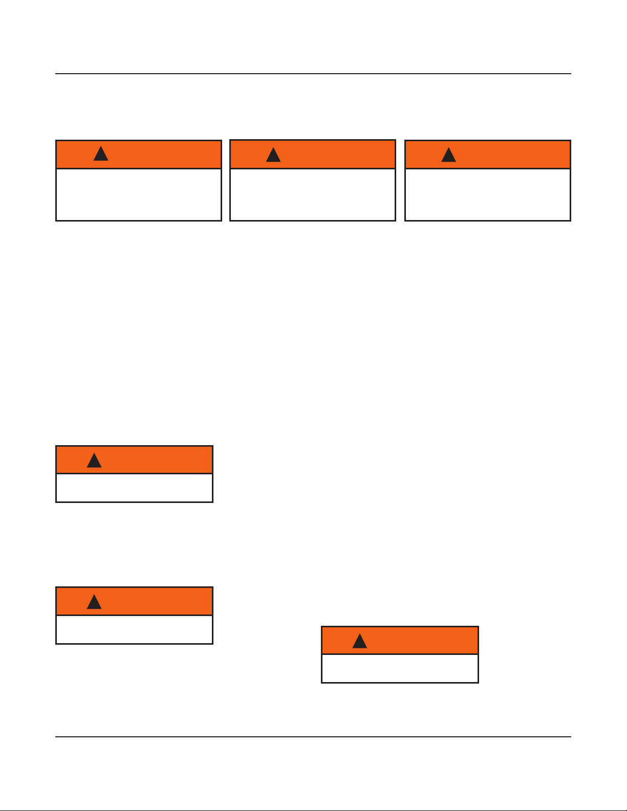
Safety Precautions
Throughout this document you may nd cautions and warnings which are dened as follows:
• WARNING: Failure to follow the instruction could result in serious injury or damage to property�
• CAUTION: Failure to follow the instruction could result in minor injury or damage to property�
Read all of these safety instructions before using the equipment�
!WARNING !WARNING !WARNING
To avoid personal injury, keep
bystanders away during setup.
!WARNING
Heavy winds can tip the
Showmobile.
!WARNING
Use extreme care around the
battery.
!WARNING
4
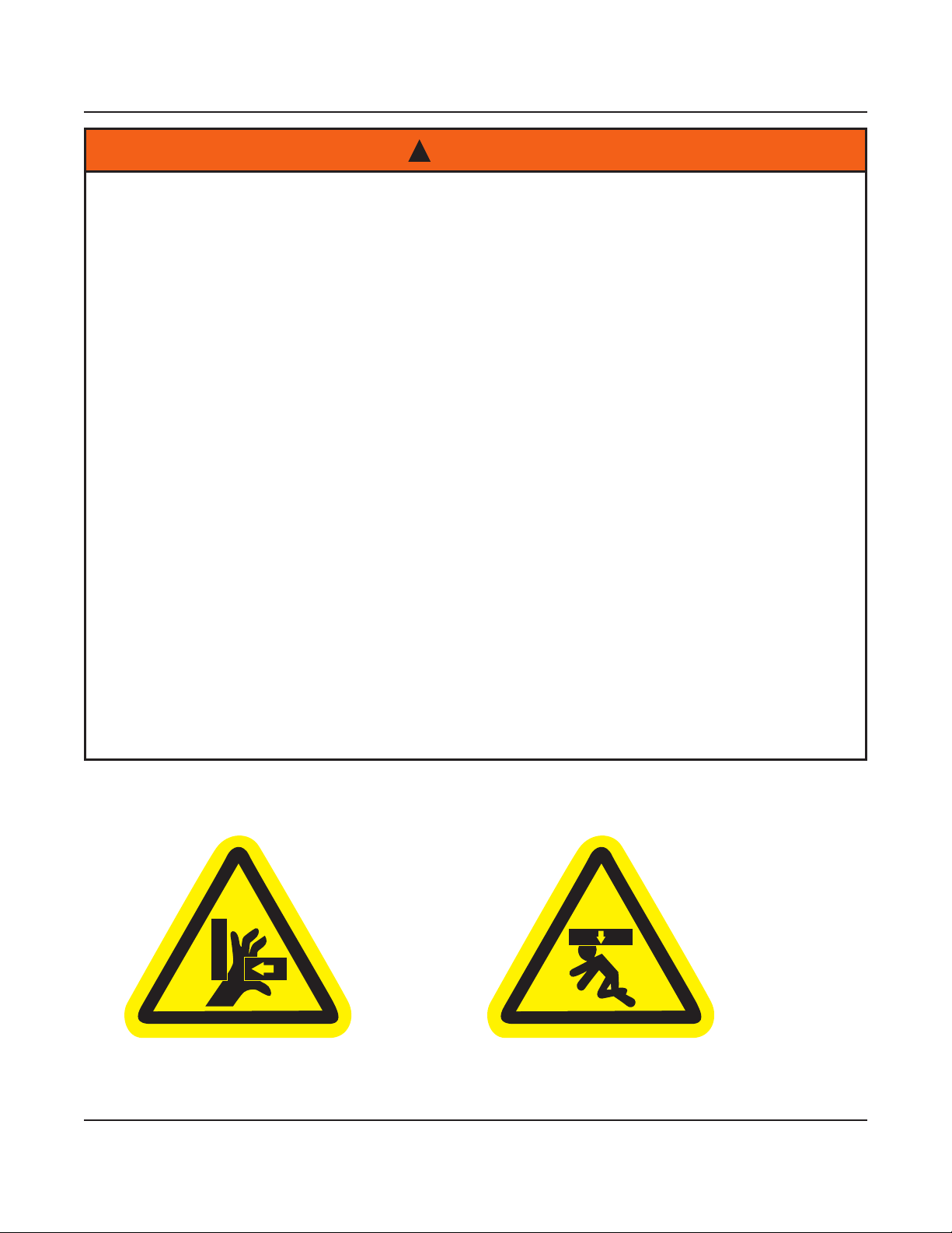
Safety Precautions (continued)
End Panel Brace Areas Underside of the Stage
Note the location of these Warning Decals
Each time you use this Showmobile unit:
• Read and understand the Owner's Manual
• Use only Authorized and Trained personnel to set up, take down, and transport the Showmobile
• Support the Showmobile on the jack stands on level ground before doing any service work
Inspect any cargo stowed inside the Showmobile:
• Never exceed the Gross Vehicle Weight (GVW) of 16,000 lb
• Put cargo in front of the axle to keep 10% -15% of the GVW on the tongue
• Distribute the cargo evenly from side to side
• Keep the load as low as possible
• Secure any cargo using the tie-downs provided
• Close and secure all doors
Check each of the tires and wheels:
• Check tires for wear, damage, and sidewall cracks
• Check tire ination pressure as stated on sidewall
• Inspect the wheels for dents and cracks
• Tighten wheel lug nuts evenly per instructions in the Owner's Manual
At the destination:
• Never raise the roof/canopy without rst extending the four stabilizing jacks and leveling the
Showmobile unit.
• Never raise, lower, or adjust the roof/canopy or stage while people are inside the Showmobile or
under the roof/canopy or stage
• Never leave the stage down or the roof/canopy open when the Showmobile is unattended
• Lower the roof/canopy if winds exceed 30 mph
• Test the shore power voltage, polarity and ground before attaching the power cord
• Never connect the shore power to an ungrounded source
• Never disconnect the ground connection
• Replace fuses with the proper rating per the Owner's Manual
!WARNING

5
Safety Precautions (continued)
Before Moving This Showmobile Unit:
• Make sure the hitch coupler is secured and all safety locks are engaged
• On level ground, adjust the hitch height to level the Showmobile unit
• Fasten the safety chains securely to the frame of the towing vehicle–cross the chains under the hitch
to allow turning
• Attach the brake breakaway switch to the towing vehicle. Make sure it engages the brakes properly
• Connect the electrical cable to the tow vehicle
• Check all lights–tail, stop, and turn signal
• Check the brake electrical operation
• Make sure the hitch jack and the four Showmobile jack stands are fully retracted
• Make sure the Roof/canopy are in the lowered position
Towing:
• Contact your dealer for proper determination of towing vehicle - make sure your towing vehicle has
a trailer towing capacity of at least 16,000 lb GVWR
• Check and adjust the brakes for correct operation at 10 mph or less in a safe area before towing
• Never exceed 55 mph
• After 50 miles, recheck tires, hitch coupler, brake operation, lights, and cargo
• An improperly loaded or towed trailer can result in loss of control of the vehicle which may result in
serious injury or death
• Be certain that the load is evenly distributed and that the rating of the axles, wheels, tires, tow
vehicle, hitch and other components are not exceeded
• The tow vehicle must be appropriately sized to the trailer. Consult your tow vehicle dealer if there
are any questions about the suitability of the vehicle.
• Be certain that the tow vehicle hitch is appropriately rated for this trailer
• Always have your brakes adjusted correctly
• Be aware of changing road and wind conditions that may aect traction or how the trailer is handling
and adjust speed accordingly
!WARNING
Reporting Safety Defects
If you believe that your vehicle has a defect which could cause a crash or could cause injury or death, you
should immediately inform the National Highway Trac Safety Administration (NHTSA) in addition to notifying
Wenger Corporation�
If NHTSA receives similar complaints, it may open an investigation, and if it nds that a safety defect exists in
a group of vehicles, it may order a recall and remedy campaign� However, NHTSA cannot become involved in
individual problems between you, your dealer, or Wenger Corporation�
To contact NHTSA, you may either call the Auto Safety Hotline toll-free at 1-800-424-9393 (or 202-366-0123) or
write to: NHTSA, U�S� Department of Transportation, 400 7th Street, SW,
NSA-11, Washington, DC 20590� You can also obtain other information about motor vehicle safety from the
Hotline�

6
Specications
Dimensions
Closed for Transport:
Length � � � � � � � � � � � � � � � � � � � � � � � � � � � � � 33'-8"
Height � � � � � � � � � � � � � � � � � � � � � � � � � � � � � 13'
Width � � � � � � � � � � � � � � � � � � � � � � � � � � � � � 8'-5"
With roof/canopy, hydraulic stage, and end panels fully open:
Length � � � � � � � � � � � � � � � � � � � � � � � � � � � � � 33'-8"
Height � � � � � � � � � � � � � � � � � � � � � � � � � � � � � 20'-10"
Width � � � � � � � � � � � � � � � � � � � � � � � � � � � � � 16'-5"
Main stage size � � � � � � � � � � � � � � � � � � � � � � � 28' x 6'-6"
Hydraulic stage size � � � � � � � � � � � � � � � � � � � 28' x 8'
Weight
Gross weight (GVW) (approximate)
Basic unit with 1 stairway � � � � � � � � � � � � 13,490 lb
Basic unit with 1 stairway and ADA lift� � � 14,240 lb
Tongue weight (approximate)
Basic unit with 1 stairway � � � � � � � � � � � � 1,600 lb
Basic unit with 1 stairway and ADA lift� � � 2,000 lb
Gross vehicle weight rating � � � � � � � � � � � � � � 16,000 lb
Electrical System
Electrical requirements � � � � � � � � � � � � � � � � � 110-volt 60 Hz, 1-phase, 3-wire, 30-amp circuit via NEMA L5-30
LED work lights � � � � � � � � � � � � � � � � � Four sets of four LED strips located in various locations across the canopy
Outlets (standard) � � � � � � � � � � � � � � � � � � � � � Two duplex outlets on stage; one duplex outlet by charger
Additional outlets (lighting upgrade) � � � � � � � Two quadplex and one duplex outlet in roof/canopy
Battery 12-volt, BCI #8D
Battery charger � � � � � � � � � � � � � � � � � � � � � � � 4-amp fully-automatic charger/maintainer
Note: Before each use, charge battery for 24 hours�
Tires
Size � � � � � � � � � � � � � � � � � � � � � � � � � � � � � LT235/85R16BG G-rated tubeless
Pressure � � � � � � � � � � � � � � � � � � � � � � � � � � � � 110 psi (verify maximum ination pressure marked on tire sidewall)
Leveling System
Standard
Four hand-cranked leveling jacks with 18" travel� Each jack is rated at 12,000 lb
Optional
Hydraulically-operated automatic leveling system, controlled by wireless remote control
Axle, Wheel and Hub Assembly
Two highway-rated torsion-type axles� Each axle has 7,200 lb capacity
Brakes
Dexter two-sided adjustable electric brake, 12-1/4" x 2-1/2", 12-volt
Breakaway Switch
12-volt, connected to on-board battery
Note: Specications are subject to change without notice.
7
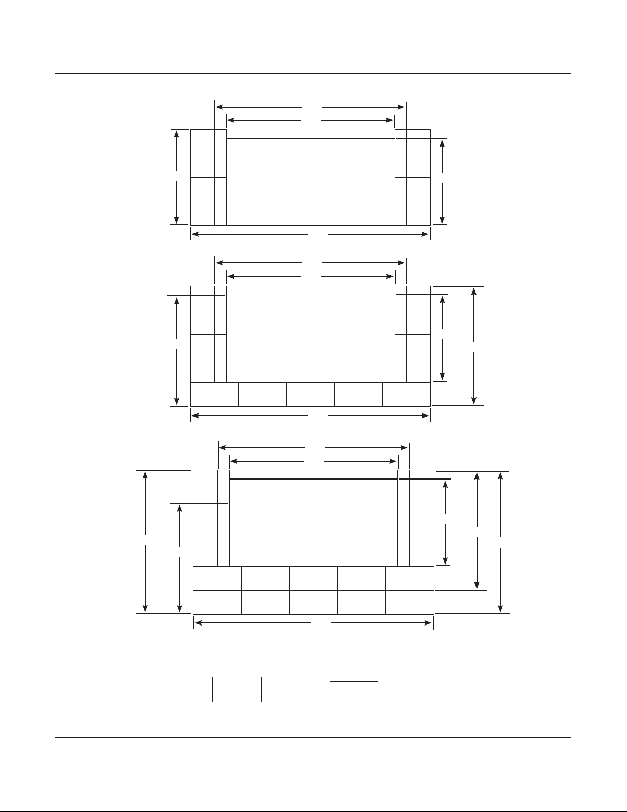
Main Stage
Hydraulic Stage
28'
32'
40'
14'-6"
16'
4'x8' Versalite 2'x8' Versalite
Specications (continued)
Typical Stage Conguration
Main Stage
Hydraulic Stage
28'
32'
40'
14'-6"
18'-6" 20'
Main Stage
Hydraulic Stage
28'
32'
40'
14'-6"
18'-6"
20'
24'
22'-6"

8
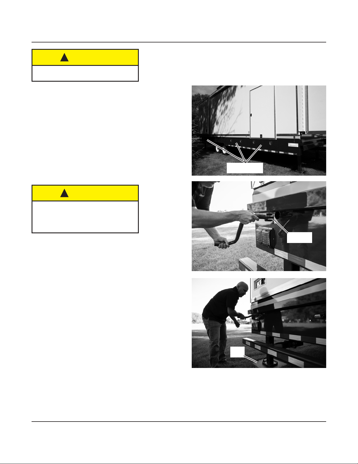
Safety
Chains
Hitch
Jack
Foot Plate Shown Lowered for Performance
Foot Plate
Release
To avoid personal injury, and vehicle
damage, never tow Showmobile with
an undersized vehicle.
!WARNING
Showmobile can tip over if towing
precautions are not followed.
!WARNING
Towing the Showmobile
Important: Moving your Showmobile from one location to another is like moving any large house trailer�
Because of the size and weight of the unit, use a tow vehicle that has adequate towing capacity and is
suitably equipped to tow a trailer of this size�
Connecting The Towing Vehicle
1. Tie-downs are located along the stage oor inside the
Showmobile� Locate cargo near tie-downs, and securely
tighten the tie-down straps which are provided� Place
cargo forward of axles to improve trailer handling�
2� Be sure that the hitch on the towing vehicle is at the
correct height so the Showmobile will be level front-to-
rear (as measured on a level surface) when towed�
3� Use the hitch jack to raise the front of the Showmobile�
Back the towing vehicle under the hitch, and secure
the hitch to the towing vehicle�
4� Attach the 12-volt electrical supply cord to the towing
vehicle, to operate the stop, turn, marker, clearance,
and license-plate lights, and electrical brakes�
5� Attach the breakaway cable to the towing vehicle�
Important: Never disconnect the breakaway cable by
pulling the pin out of the switch on the Showmobile�
If the pin is pulled from the switch, the Showmobile
brakes are activated and will drain the battery within
two hours�
6� Fully raise the Showmobile hitch jack�
7� Attach the safety chains from the towing vehicle to
the Showmobile�
8� Be sure that the Showmobile end panels are
secured in their closed positions and that all storage
and control compartment doors are locked�
9� Tongue weight as measured on a certified scale
should be at least 10–15% of the GVW�
Important Precautions While Towing
• Never tow the unit when there are strong cross winds�
• Always slow down suciently before cornering with the
Showmobile�
• Always provide adequate clearance for the corner
jacks when towing� Because of the extreme length
of the Showmobile, extreme changes in ground level
can cause its stabilizing jacks to drag: use appropriate
maneuvering to avoid this�
• Never back the Showmobile over curbs�
• Always tow Showmobile "level" or parallel to roadway�
• Always place cargo forward of axles to improve trailer
handling�

9
Towing
Vehicle Showmobile
Curb Side
Road Side
Front
End
Rear
End
12-volt
Electrical
Supply Cord
Breakaway
Cable
Hitch Jack
Crank
To avoid personal injury, use only
authorized and trained personnel.
!WARNING
Selecting a Location
Important: Read all of the Safety Precautions before beginning�
Select a rm level area on which to place the Showmobile for use. Face the road side toward the center of the
audience location�
Check for any possible obstructions (trees, power or light poles, overhanging wires, etc�) which might be in the
way of the roof/canopy when raised�
Be sure to park where there is access to a 110-volt electrical supply to operate the battery charger, for opening
and closing the roof/canopy and hydraulic stage�
In the following procedures, the sides and ends of the Showmobile are identied as indicated below.
Disconnecting the Towing Vehicle
1� Block the Showmobile's wheels with chocks�
2� Free the safety chain�
3� Disconnect the 12-volt electrical supply cord
which connects the brake and running lights to
the towing vehicle�
4� Disconnect the breakaway cable from the towing
vehicle's hitch�
Important: Disconnect the breakaway cable from
the towing vehicle, rather than pulling the
pin out of the switch on the Showmobile�
If the pin is pulled from the switch, the
Showmobile brakes are activated and will
drain the battery within two hours�
5� Pull out the release and lower the foot plate�
6� Use the crank of the hitch jack to raise the
Showmobile coupler o the towing vehicle hitch.
7� Move the towing vehicle away�
10
To avoid injury, do not use
Showmobile if the stage is not level.
!CAUTION
Leveling the Showmobile
1� Unlock and open the control and storage
compartments�
Note: Three keys are provided with the
Showmobile: one for the control compartment and
storage compartments, one for the main power lock
on the remote module, and one for the end panel
locks�
Note: There are two lockable storage compartments on
the curb side of the Showmobile, for tools,
electrical cords, sill plates, etc�
2� The Showmobile includes four jacks which are used
to level and stabilize the unit� Refer to the appropriate
procedure below, depending on whether your unit has
a manual or hydraulic leveling system�
Note: When leveling, refer to the level indicators inside
the round box on top of the hitch or use a 6'
carpenter's level�
Manual Leveling (Standard): Remove the stabilizing
crank from the storage compartment� Insert it into the
opening on the front of the Showmobile�
Pull the foot release to drop each jack's foot�
Adjust the height by turning the stabilizing crank to
lower the jack farther�
Continue to adjust each corner jack until the level
indicators on the hitch are centered�
Hydraulic Leveling (Optional): See following page�
If you are setting up the unit on a
soft surface, use sill plates (at least
18" square) to assure that the jacks
don't recess into the ground.
!CAUTION
Storage
Compartments
Sill
Plate
Stabilizing
Crank

11
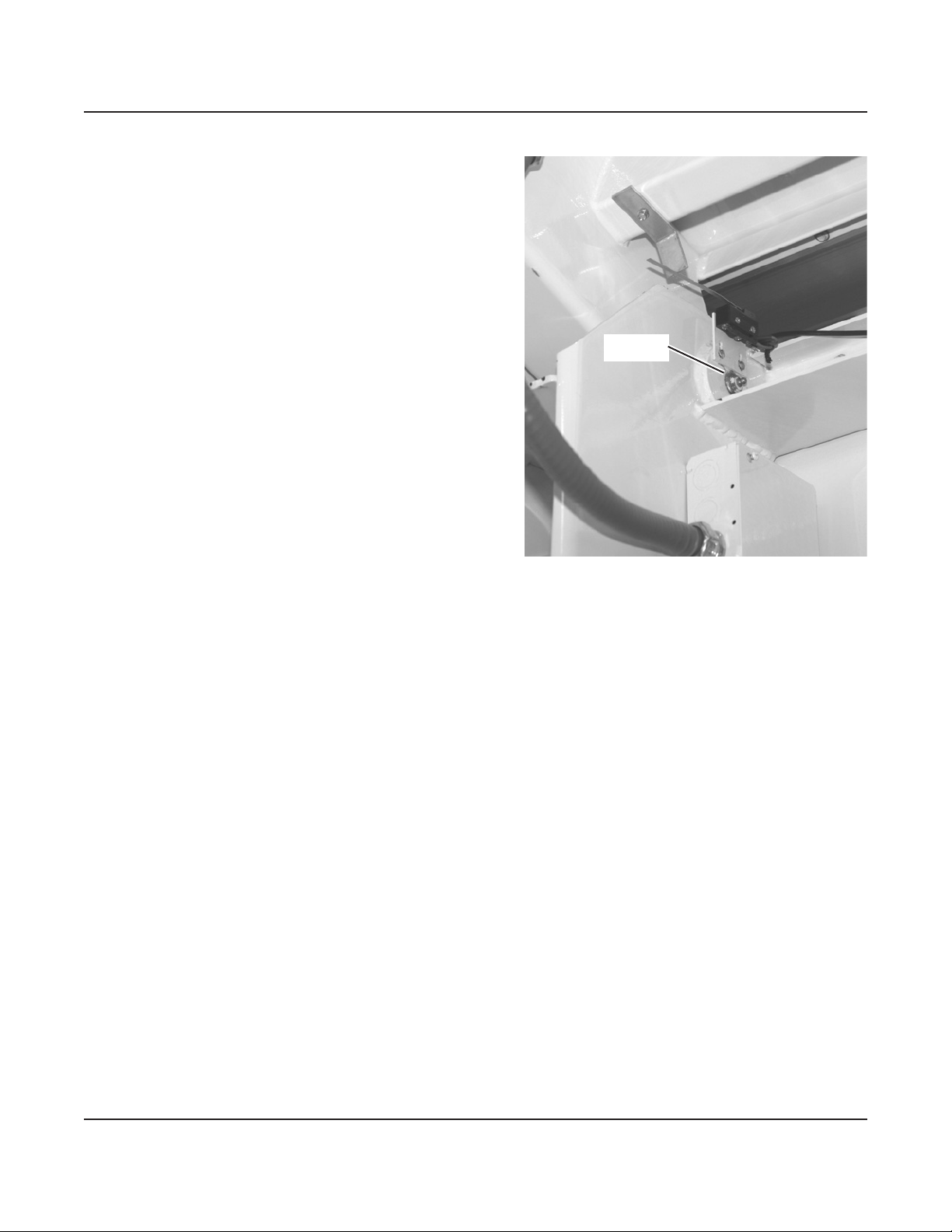
Timer
Switch
Receiver
Module
Leveling the Showmobile (continued)
Hydraulic Leveling (optional) Using the Wireless Remote Control
Important: Before using the wireless remote control, be sure the following have been completed:
• The Showmobile is unhitched from the tow vehicle�
• You have checked the front, rear, or overhead clearances required for the particular operation�
• The battery has been fully charged�
To level the unit hydraulically using the wireless remote control:
1� Open the control compartment�
2� Set the 60-minute timer switch to the desired time� The switch will not
function unless its knob is turned past the 10-minute position�
Activating the timer switch energizes the under-chassis angle sensors,
the roof limit switch (see following page), and the receiver module in the
control compartment� The remote control will not operate if the timer switch
is o and will not work unless the timer is turned on before the remote.
3� Remove the remote control from the control compartment, and set its
transmitter switch to on�
4� Move one of the upper four switches to the raise corner position�
When that stabilizing jack is in contact with the ground and the corner of
the Showmobile starts to raise, set the switch back to its neutral (center)
position�
Repeat this process on the other three corners�
5� After all four stabilizing pads are in full contact with the ground, press and
hold the red auto level button� The Showmobile will begin to raise to
properly level its chassis�
When the leveling is complete, the Showmobile will stop moving and you
will no longer hear the hydraulic motor running� Release the auto level
button�
Note: If the Showmobile stops moving but the hydraulic motor continues
to run, the slope of the ground exceeds the limits of the leveling system�
You will have to place blocks under the low end or side of the stabilizing
jack pads to increase the stroke capabilities of the jacks�
Abbreviated Procedure for Hydraulic Leveling
1� Set the timer�
2� Turn the wireless remote control on�
3� Lower all corner jacks until they are in full contact with the
ground�
4� Press and hold the auto level button�
Things to remember when operating the wireless remote control
• You may have to increase the timer switch setting
during the setup procedure, if there are interruptions�
• If the timer switch turns o before you are nished with
the remote control:
1� Turn the timer switch back on�
2� If the stabilizing jacks are already lowered into
position, you must press the red auto level button
again to regain use of the roof/canopy raise function
and the stage function�
• Turn the transmitter switch o when not in use, to save
battery power�
• When the performance is complete, you will probably
have to turn the timer switch back on (see the previous
note) before you can close up the Showmobile�
• Turning the transmitter switch o and on doesn't change
anything on the Showmobile�
• If you ever need to completely disable the hydraulic
system on the Showmobile, press the red lockout button
on top of the remote control� To activate the remote
control, turn the transmitter switch o and then on.
• You can lower the roof/canopy at any time by turning
the transmitter on and pressing lower roof/canopy�
• The roof/canopy will not raise unless the chassis is level�
12
Roof Limit
Switch
Leveling the Showmobile (continued)
13
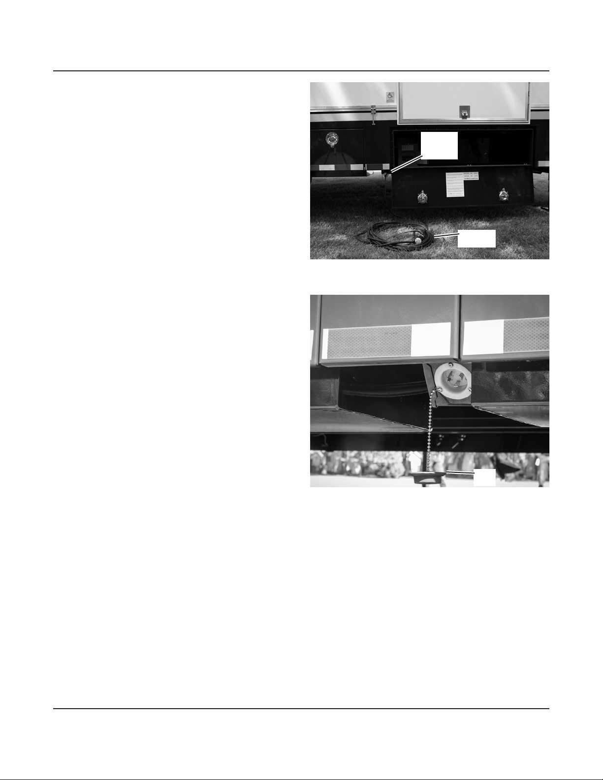
Connecting Auxiliary Power
The 12-volt hydraulic system is powered from a battery
inside the front road side corner of the Showmobile�
This battery has enough power to open and close the
roof/canopy and hydraulic stage 6 to 8 times before it
requires recharging�
All lighting and auxiliary equipment is powered by an
auxiliary 110-volt electrical system� This auxiliary system
powers the LED lighting, the outlets on the stage and
roof/canopy, and an outlet near the 12-volt battery for
use with the battery charger�
It is a single-phase 3-wire system that requires a
NEMA L5-30 plug (shown) for the power connection to
the Showmobile� The receptacle for this auxiliary power
is located on the curb side of the Showmobile, just to
the rear of the control compartment� A 50' cord with
matching plug is provided with the standard 110-volt
electrical system�
Important: Auxiliary power must be connected to keep
the battery charged (the battery powers all
hydraulic functions and the breakaway switch)�
Note: The auxiliary system can also be hard-wired to
the Showmobile, if necessary� In this case,
Wenger recommends that a licensed electrician
make the necessary connections between the
Showmobile and the auxiliary power source or,
if appropriate, provide you with a cord and
standard plug suitable for use with your local
electrical system�
Make sure the battery charger is operational�
Refer to the original Battery Charger's Instructions
received with the battery charger for more information�
Auxiliary Plug Detail
Auxiliary Plug Location
Auxiliary
Plug
Location
Auxiliary
Cord
Plug
Cap

4. Lower the end ap.
5� Unlock, open, and secure the rear end panel in the
same way�
Note: Later in this setup procedure, the end panels
can be secured at an intermediate position
(if desired)� See "Positioning the End Panels"�
14
End Panel
Stud
End Flap
Never raise or lower the roof/canopy
if the end panels are closed.
!CAUTION
Opening the End Panels
1� Unlock the front end panel� There is a key lock in
the handle assembly, and also a hole for an
optional padlock� When not in use, store the
padlock in the control compartment�
2� Press the release button,
and use the handle to open
the end panel�
3� Swing the front end panel open until it is against the back wall,
and latch it onto the stud on the curb side of the Showmobile�
This keeps the end panel out of the way while you lower the
hydraulic stage, raise the roof/canopy, and install any auxiliary
equipment�
End Panel
Handle
Handle
Release
Button
Attach
Padlock
Location Key Lock
Access
End Panel
Latch

15
Manual Leveling
Model
Auto Level
Model
Adjust stabilizing jacks
and open end panels
before raising roof/
canopy.
Be sure there are no
obstructions in the way
of the roof/canopy.
!CAUTION
!WARNING
Opening the Roof/Canopy
Note: The Showmobile must be level with all jacks
contacting the ground before opening the
canopy�
1� Manual Leveling Model:
Remove the remote control from the control
compartment, and plug it into the receptacle on
the front of the Showmobile�
The control has a keyed main power switch
(for the hydraulic system) and up/down switches
for adjusting the position of the roof/canopy and
hydraulic stage�
2� Check for any possible obstructions (trees, power or
light poles, overhanging wires, etc�) that might be in
the way of the roof/canopy when it is raised�
Note: The battery must be fully charged before you
use the hydraulic system that opens the
Showmobile roof/canopy and hydraulic stage�
3� Level the Showmobile before opening the canopy�
See "Leveling the Showmobile"�
4� Manual Leveling Model:
Activate the remote control by
turning its key switch on�
5� Open both end doors and lock
them in position�
6� With either remote control, set the
roof/canopy switch to raise until the
roof/canopy is raised just far enough
that you will be able to lower the
hydraulic stage�
For maximum stability, do not raise
the roof/canopy any higher than
necessary at this time�
If The Roof/Canopy Ever Drifts Down
The roof/canopy always should stay in position until you change it� If one end
ever begins to drift down, it is not hydraulically locked in place: immediately
raise the roof/canopy again slightly to ensure that it locks� Once hydraulically
locked, it will not drift� Bump three times if necessary� Repeat as necessary�
Note: If you ever feel that the roof/canopy is out of phase front-to-rear
(i�e�, one end is moving faster than the other), stop lowering and
immediately raise it completely until the pump goes over relief�
See "Closing the Showmobile for Travel" for the complete
re-phrasing procedure�
Remote Control
Receptacle Location
Plug In
Remote Control
16
Always clear people and objects
from the stage when moving
ceiling panels to or from storage.
Do not allow a ceiling panel
row upstage edge to touch
or strike the stage oor.
!CAUTION
!WARNING
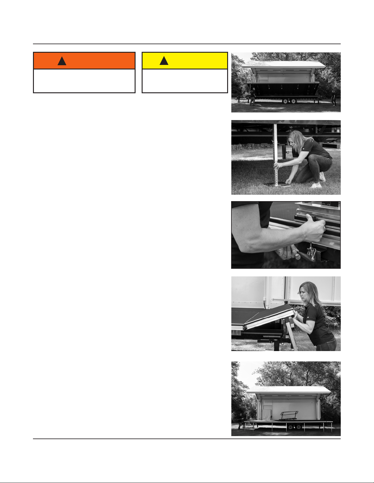
Lowering and Leveling the Hydraulic Stage
Note: The Showmobile must be level with all jacks contacting the
ground before opening the canopy�
After raising the roof/canopy, lower and level the hydraulic stage:
Note: On a Showmobile with the hydraulic leveling option, there is
a limit switch to prevent lowering or raising the hydraulic stage
if the roof/canopy is not high enough for the stage to clear or
if the ip-down panels are not unfolded and extended.
1� Set the stage switch on the remote control to lower� Stop the
stage momentarily about two-thirds of the way down, so the legs
can be released from their retaining magnets�
2� Continue lowering the hydraulic stage until it is level with the
main stage�
3� Level the hydraulic stage using leg extensions and appropriate
blocks as required:
Note: The length of each leg is adjustable� There are holes in
both the inner and outer leg members at dierent spacings.
Only one set of inside and outside holes align at any time�
You may wish to raise the hydraulic stage slightly to adjust
the length of each leg�
a. Remove the locking pin from the rst leg. Adjust the inner
member, then reinsert pin into holes that most closely align�
b� Repeat the procedure on each of the other legs�
c. Make nal adjustments as necessary to ensure that the entire
oor is level.
d� Lock the adjusting pin on each leg, using the attached
retaining clip�
e� Be sure the stage legs are supporting the stage�
Note: Return leg extensions to original position after every use
to avoid damaging stage when lowering it onto a dierent
surface contour�
4. When the hydraulic stage is level unfold the two ip-down corner
panels�
a. Move one of the two ip-down corner panels to the
performance position�
b� Unlatch the panel by pulling the handle until the latch
unhooks from the groove in the end of the panel�
c� Lift the panel upward half-way and then pull the leg from the
magnetic latch�
d� Lower the panel allowing the leg to swing downward until
the panel rests on the frame and is ush with the other stages.
e� Adjust the leg as described in the previous section, "Lowering
and Leveling the Hydraulic Stage"�
f. Lower the other ip-down corner panel by repeating steps
4a to 4e�
17
Raising the Roof/Canopy
Note: The Showmobile must be level with all jacks contacting the ground before opening the canopy�
1� To raise the roof/canopy, set the roof/canopy switch on the remote control at raise�
After the canopy is fully raised, lower the canopy to the desired performance height�
2� Manual Leveling Model
Turn the key switch to o and remove the key.
Unplug the remote control module from the front of the Showmobile and store it in a safe place
(such as the control compartment)�
Hydraulic Leveling Model (Wireless Remote Control)
Set the transmitter switch at o. Store the remote control transmitter in the control compartment or other
safe place�

18
To avoid serious injury, use star and
gravity connectors as illustrated.
!DANGER
Attaching Additional Stage Units
Additional 4' x 8' stage units are optional equipment with the
Showmobile� They can be attached to the road side of the
stage or to the ends, to increase the stage size�
There are also four special 2' x 8' stage units which attach
to the ends of the main stage, to extend it to 32" to match
additional stage setups�
These additional units attach easily to the edge of the stage or
to each other, to provide a rigid continuous surface�
To install the additional stage units:
Note: Two types of connectors are used between the
Showmobile stage and additional stage units, or
between two additional units�
Generally:
• Gravity connectors are used on the 8' sides of the
units�
• Star-shaped connectors on the 4' sides, and around
the perimeter of the stage�
If a stage is set up independently (not attached to the
Showmobile stage), use only star-shaped connectors�
Refer to the for additional clarication.
1� Insert three gravity connectors into the extrusion on the
edge of the Showmobile where the 8' side of the rst
stage unit will be attached� Position the connectors so
that one will be centered on the 8' side of the additional
unit, and the others will be about 6" from each end�
2� Plug three legs into the sockets along one of the 8' sides
of the additional stage unit�
3� Lift and tilt the stage unit until it rests on the connectors�
4� Lower the stage unit� If properly installed, its top surface
should be level with the Showmobile stage surface and it
should be rmly held by the connectors.
5� Level the stage unit to match the Showmobile stage by
adjusting the three legs:
a� If necessary, pull the leg pin and slide the leg
extension in or out until it snaps into the proper hole�
b. Screw the leveling foot in or out to make ner
adjustments�
6� Install the remaining stage units in the same way�
For stability, a star-shaped connector must be used in all
locations as shown�

19
Main Stage
Hydraulic Stage
Hydraulic Stage
Main Stage
For a Stage Extension
For Wider Stage Wings
Sample connections of optional stage units shown�
Additional units can be added to the sides or front (or both)�
Gravity Connector
Star Connector
Buttery Clip
Leg
Attaching Additional Stage Units (continued)

20
Secure both lock knobs and level
the steps before using stairway.
!WARNING
Attaching Stairways
The portable stairway can be located anywhere around the perimeter of the hydraulic stage oor or
stage extension�
Attaching Accessories
A full line of railings, drapery closures, audience seating platforms, and other stair units are available�
Attach drapery closures using the hook and loop tape provided�
Tighten the
Thumb Screw
Attaching a Stairway
1� With two people lifting the stairway, raise its lower
end until you can slip the top of the two clamps
(on the stairway) into the channel on the edge of
the stage�
2� Rotate the stairway back down, being sure the
clamps remain in the stage channel�
3� Tighten the thumb screw on each clamp, to secure
the stairway to the stage�
4� Lock the stairway by securely tightening the two
knobs (one on each side) at the middle of the
stairway�
Adjusting a Stairway
1� Loosen the stairway lock knobs�
2� Adjust the stairway angle by pushing on the ends of the stair railings�
Adjust so the steps are perfectly level�
3� Tighten the lock knobs�
Table of contents
Popular Tent manuals by other brands

Weather Fast
Weather Fast 1934796 Assembly manual

HAMPTON BAY
HAMPTON BAY GFM00469A-CPY Use and care guide

NRS Relief
NRS Relief UNHCR Standard Assembly manual

Classic Accessories
Classic Accessories 73012 instructions

Elk Mountain Tents
Elk Mountain Tents YUKON BELL TENT instructions

Beavertail
Beavertail Flip Top Blind instructions


