Wenglor OSEI Z0103 Series User manual

EN
Operating Instructions
Translation of the Original Operating Instruction
Subject to change without notice
Available as PDF version only
Status: 11.07.2017
www.wenglor.com
OSEIxxxZ0103
OEEIxxxU0135
Light Curtain for Measuring Tasks

2
Table of contents
1. Proper Use 4
2. Safety Precautions 4
3. EU Declaration of Conformity 4
4. Technical Data 5
4.1. Datasheet 5
4.2. Connection Diagrams 6
4.3. Housing Dimensions 6
4.4. Control Panel 7
4.5. Complementary Products 7
5. Mounting instructions 8
5.1. Mounting 8
5.1.1 Mounting with the BEF-SET-33 8
5.2. Alignment 9
6. Initial Start-Up 10
6.1. Setup 10
6.2. Overview of functions 11
6.3. Menu Structure 12
6.4. Beam Arrangement 13
6.5. Synchronizing Beam 13
6.6. Test Input Function 13
6.7. Error Output Function 14
6.8. Tolerance 14
7. Settings 16
7.1. Run 16
7.2. Pin Function 16
7.3. A1 Switch 17
7.3.1 Teach Beams 17
7.3.2 Teach-In Pattern 18
7.3.3 Two-Step Teach-In 19
7.3.4 Teach-In Range 20
7.4. E/A2 23
7.4.1 E Teach 23
7.4.2 E Setup 23
7.4.3 A2 Switch 23
7.4.4 A2 Error 24
Table of contents

3
Light Curtain for Measuring Tasks
7.5. Analog 24
7.5.1 Position 24
7.5.2 Web Edge 26
7.6. Blanking 28
7.7. Threshold 29
7.8. E/A Test 29
7.9. Expert Menu 30
7.10. Display Definition 30
7.11. Language 31
7.12. Information 31
7.13. Reset 31
7.14. Password 32
7.15. Start Setup 33
8. IO-Link Parameter and Process data 33
9. Maintenance Instructions 42
10. Proper Disposal 42

4Proper Use
1. Proper Use
This wenglor product is used in accordance with the following mode of operation:
Light curtains for measuring tasks operate according to the barrier principle, so the transmitter and receiver are
integrated in separate housings. The switch output switches and an analog output reads out corresponding
voltage or current depending on how many and which light beams are interrupted. The function of the transmit-
ter can be tested using a test input.
Light curtains for measuring tasks can be adjusted intuitively and easily via the menu-driven graphic display. A
bar graph makes intermittent rays visible, making alignment, commissioning and troubleshooting much easier.
2. Safety Precautions
• These instructions are an integral part of the product and must be kept on hand for the entire duration of
its service life.
• Read the operating instructions carefully before using the product.
• Installation, start-up and maintenance of this product has only to be carried out by trained personnel.
• Tampering with or modifying the product is impermissible.
• Protect the product from contamination during initial start-up.
• Not a safety component in accordance with the EU Machinery Directive.
3. EU Declaration of Conformity
The EU declaration of conformity can be found on our website at www.wenglor.com in download area.
RoHS
5
Light Curtain for Measuring Tasks
4. Technical Data
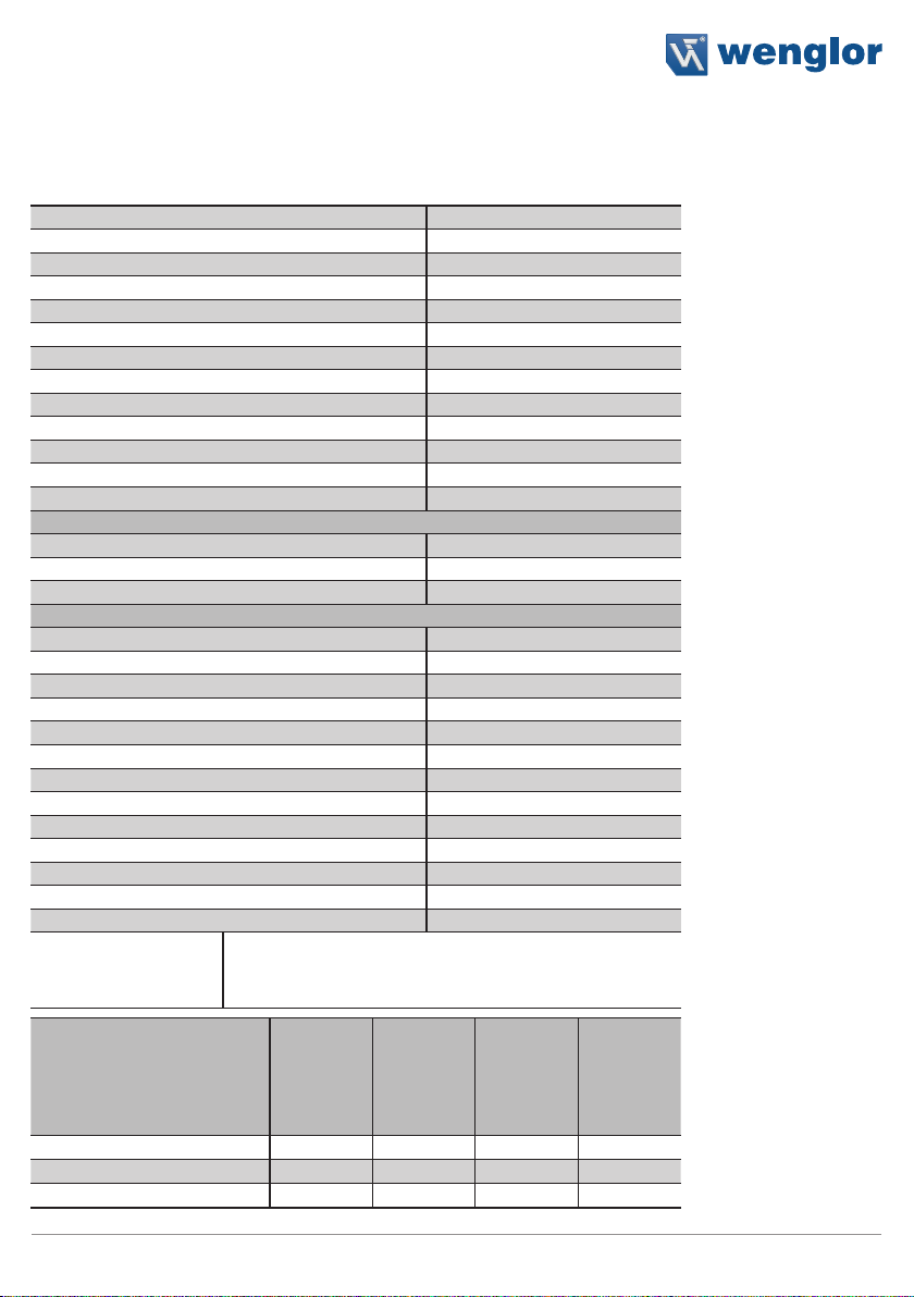
4.1. Datasheet
Range 2000 mm
Opening Angle 10°
Beam Distance 2 mm
Supply Voltage 10…30 V DC
Current Consumption (Ub = 24 V) < 60 mA
Temperature Drift < 10 %
Temperature Range –25…60 °C
Housing Aluminium
Reverse Polarity Protection yes
Full Encapsulation yes
Degree of Protection IP65
Connection M12×1
Protection Class III
Emitter
Light Source Infrared Light
Wave Length 880 nm
Service Life (T = 25 °C) 100000 h
Receiver
max. Ambient Light 10000 Lux
ON-/OFF-Delay 0…10000 ms
Switching Output Voltage Drop < 2,5 V
Switching Outputs 2
Switching Output/Switching Current 100 mA
Residual Current Switching Output < 50 mA
Analog Output 0…10 V
Analog Output 4…20 mA
Short Circuit Protection yes
Overload Protection yes
IO-Link Version 1.0
Password Protection yes
Menu language yes
Output Function
Configurable as PNP or push-pull
NC/NO, switchable
IO-Link
Analog Output
Order No.
OSEI501Z0103
OEEI501U0135
OSEI102Z0103
OEEI102U0135
OSEI152Z0103
OEEI152U0135
OSEI202Z0103
OEEI202U0135
Measurement Field Height (MFH) 50 mm 100 mm 150 mm 200 mm
Switching Frequenzy 150 Hz 85 Hz 60 Hz 45 Hz
Response Time 3 ms 6 ms 8 ms 11 ms

6Technical Data
4.2. Connection Diagrams
Emitter Receiver
1018
188
+ Supply Voltage “+”
– Supply Voltage “0 V”
U Test Input
A1/ Switching Output 1/IO-Link
E/A2 Input/Output programable
O Analog Output
nc not connected
7
Light Curtain for Measuring Tasks
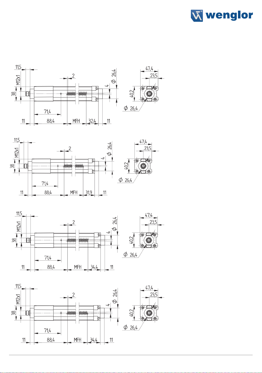
4.3. Housing Dimensions
Emitter
OSEI501Z0103
OSEI102Z0103
OSEI152Z0103
OSEI202Z0103
8Technical Data
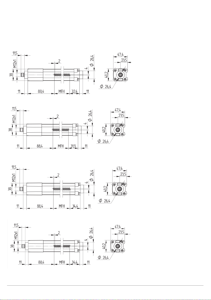
Receiver
OEEI501U0135
OEEI102U0135
OEEI152U0135
OEEI202U0135

9
Light Curtain for Measuring Tasks
4.4. Control Panel
Emitter Receiver
K3
04
23 20 22
60
X2
04 = Function Display 22 = Up Button
60 = Display
23 = Down Button
20 = Enter Button
4.5. Complementary Products
wenglor offers Connection Technology for field wiring.
Suitable Connection Technology No.
2
35
S02 S06
Suitable Mounting Technology No.
700
IO-Link Master

10 Mounting instructions
5. Mounting instructions
During operation of the Sensors, the corresponding electrical and mechanical regulations, as well as safety
regulations must be observed. The Sensor must be protected from mechanical impact. Install the device such
that its installation position cannot be inadvertently changed. Use of the Z0033 accessory is recommended in
order to improve EMC immunity.
5.1. Mounting
The mounting of the Light Curtains is made over the BEF-SET-18 or BEF-SET-33.
5.1.1 Mounting with the BEF-SET-33
First secure the mounting clamp to the Light Curtain with the screws. The screws should remain accessible
after mounting. In this way, the Light Curtain can be adjusted at a later point in time. The Light Curtain is then at-
tached to the machine etc. with the BEF-SET-33. Neither excessively small torques (too little protection against
vibration) nor excessively large torques (possible damage to the retainer) may be used during installation.
Mounting screws and nuts required for attachment to the machine etc. are not included in the scope of delivery.
This manual suits for next models
9
Table of contents
Other Wenglor Safety Equipment manuals


Popular Safety Equipment manuals by other brands

Lanex
Lanex PB-20 instruction manual

SKYLOTEC
SKYLOTEC ANCHOR ROPES Instructions for use

Besto
Besto Buoyancy Aid 50N Instructions for use

TEUFELBERGER
TEUFELBERGER NODUS Manufacturer's information and instructions for use

Troy Lee Designs
Troy Lee Designs Tbone Product owners manual

Innova
Innova Xtirpa Instruction and safety manual

bolle SAFETY
bolle SAFETY B810 quick start guide

SHENZHEN FANHAI SANJIANG ELECTRONICS
SHENZHEN FANHAI SANJIANG ELECTRONICS A9060T instruction manual

Hiltron security
Hiltron security POWER8E Installation and use manual

Salewa
Salewa MTN SPIKE user manual

Hatco
Hatco B-950P installation guide

Sitec
Sitec TX MATIC operating manual


