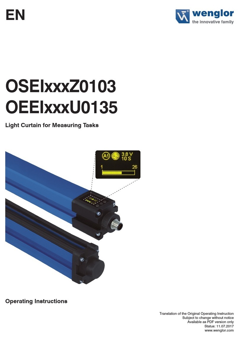
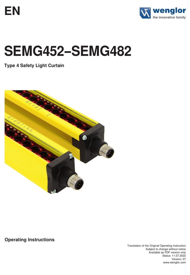
Wenglor SB4-I User manual

Original operating instructions
Available as PDF version only
Status: 22.05.2019
Version: 10
www.wenglor.com
EN
SB4-I
Safety Light Array
Operating instructions

EN
2
Table of Contents
1. Introduction......................................................................................................... 4
1.1 General Information Regarding this Document ....................................................................... 4
1.2 Function and Use for Intended Purpose .................................................................................. 4
1.3 Brief Explanation of Function- and Operating Modes............................................................... 4
1.4 Explanation of symbols ............................................................................................................ 5
2. Description of the Safety Device........................................................................ 6
2.1 General ..................................................................................................................................... 6
2.2 Features ................................................................................................................................... 6
2.3 Layout ........................................................................................................................................ 7
2.4 Control and Display Elements................................................................................................... 7
2.5 Applications Examples .............................................................................................................. 8
3. Instructions for Use and Safety Precautions .................................................... 9
3.1 General Instructions for Use and Safety Precautions ............................................................... 9
3.2 Securing the Danger Zone ...................................................................................................... 10
3.3 Calculating Safety Clearance .................................................................................................. 10
3.4 Minimum Clearance to Reflective Surfaces............................................................................. 12
3.5 Avoidance of Reciprocal Influence Amongst Several Light Barrier Systems ......................... 13
4. Connection and Installation to the Machine ................................................... 14
4.1 Installation................................................................................................................................ 14
4.2 Connection to the Machine .................................................................................................... 15
4.3 Default Settings........................................................................................................................ 16
5. Light Array Operation ....................................................................................... 17
5.1 Settings .................................................................................................................................... 17
5.1.1 Using the Aligning Tool RF................................................................................................ 17
5.1.2 Using the SZ0-LAH1 Aligning Tool.................................................................................... 18
5.1.3 Adjustment Procedure ..................................................................................................... 18
5.2 Function Modes ...................................................................................................................... 19
5.2.1 Safety Operating Mode .................................................................................................... 19
5.2.2 Restart Inhibit and start-up inhibit..................................................................................... 20
5.2.3 Contactor Monitoring ........................................................................................................ 23
5.3 Functions ................................................................................................................................. 26
5.3.1 Fix Blanking....................................................................................................................... 26
5.3.0.2 Principle ...................................................................................................................... 26
5.3.0.3 Fix Blanking Procedure .............................................................................................. 29
5.3.0.4 Calculating Safety Clearance ..................................................................................... 30
5.3.5 Reduced Resolution.......................................................................................................... 30
5.3.0.6 Principle ...................................................................................................................... 30
5.3.0.7 Reduced Resolution Procedure ................................................................................. 32
5.3.0.8 Calculating Safety Clearance ..................................................................................... 33
5.4 Cascading................................................................................................................................ 33
5.4.1 Principle............................................................................................................................. 33
5.4.2 Cascading Procedure ....................................................................................................... 34
5.4.3 Functions........................................................................................................................... 36
5.4.4 Coding............................................................................................................................... 37
Table of Contents

3
Safety Light Array
6. Expanding the Light Array System .................................................................. 38
6.1 Relay Unit................................................................................................................................. 38
6.2 Muting Module......................................................................................................................... 39
6.3 Connection to a PC.................................................................................................................. 40
6.4 Deflection Mirrors..................................................................................................................... 41
7. Display............................................................................................................... 42
7.1 Display of Operating Modes.................................................................................................... 42
7.2 Diagnostic information............................................................................................................. 43
8. Condensed Start-Up Instructions .................................................................... 44
9. Inspection Instructions..................................................................................... 45
9.1 Inspection Prior to Initial Start-Up............................................................................................ 45
9.2 Daily Inspection and Maintenance of the Effectiveness of the Safety Device ........................ 45
10. Environmentally Sound Disposal..................................................................... 46
11. Dimensions and Weights.................................................................................. 47
11.1 SB4-50IE050C1/SB4-50IS050C1............................................................................................. 47
11.2 SB4-40IE080C1/SB4-40IS080C1............................................................................................. 48
11.3 SB4-30IE090C1/SB4-30IS090C1............................................................................................. 49
11.4 Mounting Bracket BEF-SET-33 ............................................................................................... 50
12. Technical Data................................................................................................... 51
12.1 Safety Light Array..................................................................................................................... 51
12.2 System Components ............................................................................................................... 52
12.2.1 Relay Unit SG4-00VA000R2.............................................................................................. 52
12.2.2 Adapter Box A485-232 ...................................................................................................... 52
12.2.3 Laser Alignment Aid SZ0-LAH1 ........................................................................................ 52
12.2.4 Mounting Elements ........................................................................................................... 52
12.2.5 Connection Line ................................................................................................................ 53
12.2.6 Connection Cables............................................................................................................ 53
12.2.7 Interface Cable .................................................................................................................. 53
13. Checklist ........................................................................................................... 54
14. Certification....................................................................................................... 55
15. EU Declaration of Conformity .......................................................................... 56

EN
4 Introduction
1. Introduction
1.1 General Information Regarding this Document
This document is intended to serve as a set of operating instructions for personnel which has been authorized and
commissioned by the machine manufacturer or operating company to connect the safety device, integrate it into
the machine, start it up, configure it and maintain it in accordance with the specified stipulations.
Due to the fact that they describe the operation of a safety device, these operating instructions are of a binding
nature.
The wenglor safety device with the designation “Light Array” is described in these operating instructions.
1.2 Function and Use for Intended Purpose
The light curtain monitors the safety field between the transmitter and the receiver. If the safety field is penetrated
by an obstruction, a switching command is triggered. This switching command may prevent initialization of a haz-
ardous machine motion, or may stop an action which has already been started.
Use of the light curtain is only permissible if:
• Hazardous motion can be stopped by electrical means using the light curtain’s safety output
• Adequate detection of possible obstruction is assured with existing resolution
1.3 Brief Explanation of Function- and Operating Modes
Cascading
Safety devices can be series connected such that they all drive a single safety output in order to monitor several
safety fields simultaneously. Cascaded safety devices demonstrate the same performance characteristics as a
single safety device.
Contactor Monitoring
An operating mode for which switching performance of the contacts at an external relay is dynamically monitored.
The contacts must close fully within a specified period of time.
Fix Blanking
This operating mode is required for applications including objects which continuously protrude into the safety
field, thus interrupting specific light beams originating from the safety light curtain. Intrusions into any other point
within the safety field cause the output to switch and stop hazardous motion.
Reduced Resolution
This function reduces the resolution electronically. Thus objects that are smaller than the selected resolution don’t
deactivate the safety output. The function can also be used to prevent machining chips from interfering with cor-
rect functioning of the Safety Light Array.
Restart Inhibit
A function which prevents a machine from starting up automatically after it has been switched on. The machine
can only be enabled by activating an acknowledgement key.
Safety Operating Mode
In this operating mode, the switching outputs are disabled when the safety field is penetrated. The switching out-
puts are automatically enabled after penetration of the safety field is ended.
Safety Output – OSSD (Output Signal Switching Device)
The output of the contactless safety device which is connected to the machine controls. The safety output is deac-
tivated when the safety field is interrupted.
Signal Output
A semiconductor output for auxiliary functions without safety monitoring.

5
Safety Light Array
Start-Up Inhibit
This function is activated along with the „Restart Inhibit Function“. When power supply is switched on (e.g. after a
power failure), the safety outputs (OSSD) remain in the off state. Acknowledgement is accomplished by activating
an acknowledgment key.
1.4 Explanation of symbols
NOTE!
A note draws attention to useful tips and suggestions, as well as information
regarding efficient, error-free use.
DANGER!
This word indicates a hazard with a high degree of risk which, if not avoided,
results in death or severe injury.

EN
6 Description of the Safety Device
2. Description of the Safety Device
2.1 General
The light curtain monitors the safety field between the transmitter and the receiver. If the safety field is penetrated
by an obstruction, a switching command is triggered. This switching command may prevent initialization of a
hazardous machine motion, or may stop an action which has already been started.
Use of the light curtain is only permissible if:
• Hazardous motion can be stopped by electrical means using the light curtain’s safety output
• Adequate detection of possible obstruction is assured with existing number of beams and selected beam
clearance.
• Use of a type 4 light barrier is permissible
2.2 Features
• Safety device per EN 61496-1
• TÜV approval
• Body protection with a beam clearance of 300, 400 or 500 mm
• Visible red light
• PNP semiconductor safety outputs
• PNP signal output
• Fix Blanking
• Electronically reduced resolution
• Simple cascading
• Serial interface with visualization program
• Restart inhibit
• Monitoring of external relays
• Muting (optional)
• Relay unit (optional)
• Coding Controls Controls
Displays Displays
OSSDs
Supply Voltage 24 V
Slave
Supply Voltage 24 V
Slave
Slave Input 1
Slave Input 2
Supply Voltage 24 V
Supply Voltage 24 V
OSSD 1
OSSD21
Acknowledgement Input
Contactor Monitoring
Emitter Receiver

7
Safety Light Array
2.3 Layout
Receiver
Emitter
Display Element
Individual Beam
Spacer Plate Beam Distance
Beam
Consists of 9 individual beams
2.4 Control and Display Elements
Receiver
Display Element Function
8) Serial Communication
7) Timing
6) Cascading
5) Reduced Resolution
3) Fix Blanking
2) Contactor Monitoring
1) Restart Inhibit
8)Serial Communication
7)Timing
6)Cascading
5)Reduced Resolution
3)Fix Blanking
2)Contactor Monitoring
1)Restart Inhibit
Display 2 Display 1
Blanking
Alignment (YE) Failure (RD)
OSSD off (RD) OSSD on (GN)
Enter Button
Dip-Switch S1
Alignment-/Blanking LED (YE) Alignment/
fix blanking display
Failure-LED (RD) Error display
OSSD off (RD) OSSD status display
OSSD on (GN) OSSD status display
Display 1 Display of the selected function or
operating mode
Display 2 Display of the selected function
or operating mode
Dip-Switch Selection of functions and
operating modes
Enter Button Acknowledgment of a selection
Emitter
Display Element Function
Failure (RD)
Enter Button
Normal
Operation (GN)
Failure-LED (RD) Error display
Normal Operation (GN) Power supply indicator
Enter Button Acknowledgment of a selection

EN
8 Description of the Safety Device
2.5 Applications Examples
Safety protection at:
• Presses
• Saws
• Textile machinery
• Transfer lines, assembly lines
• Packaging machines
• Woodworking machines
1st example: restricting access and securing specific areas
Danger Zone
Emitter Receiver
Top View Side View
2nd example: use with path-folding mirrors
Danger Zone
Emitter
Receiver
Deflection Mirror
Top View Side View

9
Safety Light Array
3. Instructions for Use and Safety Precautions
3.1 General Instructions for Use and Safety Precautions
Observe the following points in order to assure safe use of the Safety Light Array for its intended purpose.
Applicable national and international requirements apply to installation and use of the Safety Light Curtain, as well
as to initial start-up and periodic technical testing, in particular:
• EN standards
• Accident prevention regulations
• Occupational health and safety requirements
• EU machinery directive
The manufacturer of, and the company who operates the machine at which the Safety Light Curtain is used must,
on their own initiative, agree upon and adhere to all applicable safety regulations and rules in cooperation with the
responsible authorities. It is absolutely essential to adhere to all directions included in these operating instructions,
in particular the inspection procedures.
Contactless safety devices may only be used at power operated machinery whose controls can be electrically
influenced such that hazardous motion can be stopped immediately in all operating phases.
Additional measures may be necessary in order to assure that the ESPE does not malfunction or fail in a danger-
ous fashion due to other types of light which are used in the respective application (e.g. resulting from the use of
cordless controllers on cranes, emission due to welding sparks or the effects of stroboscope light).
Testing must be performed by an expert prior to initial start-up of the ESPE. Testing must establish flawless
interaction of the ESPE together with the controls of the power operated machinery, and correct installation in
accordance with these safety precautions.
Testing must be conducted by qualified persons, or persons who have been authorized and engaged specifically
to this end, and must be documented in a fashion which can be readily retraced at any point in time.
The cascading terminals on the sensor and the receiver may only be used to connect additional Light Arrays.
Connection of other power consumers is impermissible.
Changes to device configurations may impair the respective devices’ protective functions. For this reason, the
effectiveness of the safety device must be retested each time its configuration is changed. The person who makes
the change is also responsible for assuring that the safety function of the device is maintained.
The operating instructions must be made available to the operator of the machine at which the Safety Light Array
is used. The machine operator must received instruction from qualified persons, and must be required to read the
operating instructions.

EN
10 Instructions for Use and Safety Precautions
The following standards must be observed during use of the light curtain:
EN ISO 13855 Machine safety: arrangement of safety devices in consideration of approach
speeds of body parts
EN ISO 12100 Machine safety: General design guidelines – risk assessment and risk minimization
EN ISO 13857 Machine safety: Safety distances to prevent hazard zones being reached by
upper and lower limbs
EN 349 Machine safety: Minimum gaps to avoid crushing of parts of the human body
EN ISO 13850 Machine safety: emergency stop devices
EN ISO 14119 Machine safety: Interlocking devices associated with guards
All specified data make reference to the following revision level: 22.05.2019
Technical changes to the product described herein, printing errors and/or any possible incompleteness of this
product description may not be construed as cause for asserting any legal claims whatsoever against wenglor
sensoric GmbH.
3.2 Securing the Danger Zone
The danger zone must be secured by means of the light curtain alone, or by means of the light curtain in combi-
nation with additional mechanical safety devices. Walking around the safety field at the side, as well as stepping
over and/or under the safety field must be prevented in any case. It must be impossible to approach the point of
danger without passing through the safety field.
The safety field is located between the line at which light is emitted at the emitter and the line at which light is
received at the receiver. The boundaries of the safety field are obvious on the devices.
3.3 Calculating Safety Clearance
Calculation of safety clearance S is based upon the EN ISO 13855 standard. However, if any special directives
and standards apply to the respective machine, these must be taken into consideration as well. Each contactless
safety device must be mounted such that stepping or reaching into the danger zone is precluded. If required, this
may also be accomplished by means of additional, mechanical safety devices.
Safety clearance S is the minimum distance in mm, measured from the danger zone to the safety field, and is
calculated per EN ISO 13855 as follows:
S [mm] = ( K [mm/s] × T [s] ) + C [mm]
S = minimum clearance in mm, measured from the danger zone to the safety field
K = approach speed in mm per second
T = t1+t2 = total response time in seconds
t1 = safety device response time in seconds
t2 = machine or process over-travel time in seconds
C = additional clearance depending upon beam clearance/resolution in mm

11
Safety Light Array
Over-Travel Time T
Due to the fact that interrupting the safety field during hazardous motion does not result in immediate stopping of
the machine, over-travel time T must be taken into consideration. The distance between the safety field and the
point of danger must thus be large enough to assure that the point of danger cannot be reached until hazardous
motion has come to a standstill.
Total over-travel time T is the sum of maximum response time of the contactless safety device (t1) and maximum
over-travel time of the hazardous motion (t2). Machine over-travel time must be determined by means of repeated
measurement prior to initial start-up, and each time the machine is retooled (set up).
The response time of the ESPE depends upon the height of the safety field (see table).
Type Designation
(for Transmitter and Receiver)
Beam
Clearance
Number of
Beams
Number of
Individual Beams
Response TIme
SB4-50Ix050C1 500 mm 2 18 Beams 5,7 ms
SB4-40Ix080C1 400 mm 3 27 Beams 8,2 ms
SB4-30Ix090C1 300 mm 4 36 Beams 10,0 ms
Approach / Reach-In Speed Constant K
Amongst other factors, safety clearance depends upon the maximum reach-in or walking speed of the person
penetrating the safety field.
Safety Margin C
Safety margin C depends upon the respective resolution of the light curtain.
Perpendicular Approach to the Safety Field
The following applies for an ESPE with a resolution or beam clearance of greater than 40 mm:
K = 1600 mm/s
C = 850 mm (standard arm range)
S = (1600 mm/s × T) + 850 mm
Beam Clearance
Height Above
Reference Level
Safety Clearance
Direction of Safety
Field Penetration

EN
12 Instructions for Use and Safety Precautions
The number of utilized beams is based upon the EN ISO 13855 standard in consideration of the relevant
level C standard.
The minimum and maximum heights specified in the table may not be exceeded or fallen short of respectively.
Beam heights for securing areas in accordance with EN ISO 13855:
Number of Beams Beam Clearance in mm Height Above Reference Level in mm
4 300 mm 300, 600, 900, 1200
3 400 mm 300, 700, 1100
2 500 mm 400, 900
Example:
Selected parameters: safety device with 300 mm beam clearance and 4 beams, vertical installation
Assuming
machine over-travel time t2= 20 ms
Safety Light Array response time SB4-30IE090C1 t1= 10 ms
Approach speed K = 1600 mm/s
Safety clearance
Safety clearance S = K×T+C
= K×(t1+t2)+C
= 1600 mm/s×(0,01 s+0,02 s) + 850 mm
= 898 mm
3.4 Minimum Clearance to Reflective Surfaces
If reflective surfaces are located within the aperture angle between the transmitter and the receiver, reflection may
result which could cause an obstruction to go undetected. For this reason, a minimum clearance mbetween
reflective objects and the optical axis must be maintained.
Beam angles are taken from the IEC 61496-2 standard. They represent worst case values. Actual values are lower.
m
α
α
Danger Zone
Center Beam
Emitter Receiver
Reflective
Object
Light Bundle
interrupted
m = tan a× (Distance Transmitter – Receiver)
2468101214161
82
0
0,10
0,20
0,30
0,40
0,50
0,60
0,70
0,80
0,90
0,131
Minimum Clearance m in m
Range in m
a = Opening Angle of Emitter and Receiver Optic
a = ±2,5°

13
Safety Light Array
3.5 Avoidance of Reciprocal Influence Amongst Several Light Barrier Systems
If a receiver is located within the beam path of a neighboring emitter, reciprocal influence of the sensor function
may occur, thus resulting in erroneous switching and failure of the safety function.
Emitter 1 Emitter 2
Receiver 1 Receiver 2
DANGER!
In order to assure error-free operation of several light barrier systems at a single machine
(i.e. several Connector Units with their respective Safety Light Barriers), the receiver may only be
exposed to light from the emitters of the same light barrier system. In order to assure that this is the
case, a non-parallel arrangement (see figure) or a lateral clearance of at least 2 × m should
be used (see section 3.4).
Shielding from neighboring sensor systems, for example through the use of partitions, may also prevent reciprocal
influence.
Emitter 1 Receiver 2
Receiver 1 Emitter 2

EN
14 Connection and Installation to the Machine
4. Connection and Installation to the Machine
4.1 Installation
There are three options for mounting the emitter and the receiver.
• Attachment with BEF-SET-33 (included)
• Attachment with BEF-SET-18 (System Components)
• Attachment with BEF-SET-36 (installation in safety column)
Mounting with the BEF-SET-33
First secure the mounting clamp to the Light Array with the screws. The screws
should remain accessible after mounting. In this way, the Light Array can be adjusted
at a later point in time. The Light Array is then attached to the machine etc. with the
BEF-SET-33. Avoid excessively small (minimal protection against vibration) or large
(possible damage to the retainer) tightening torques for the mounting components.
The mounting screws and nuts are not included in the scope of delivery.
The safety function is independent of the installation position. As long as the specified
instructions are adhered to, the Light Arrays can be mounted as desired (e.g. upside
down).
In order to assure flawless functioning of the Light Array, the two matched compo-
nents (transmitter and receiver) must be aligned to one another.
It is advisable to mount the light curtain for initial start-up such that alignment can still
be adjusted to an adequate extent. wenglor offers accessories which allow for easy
adjustment.
The controls must be accessible for initial start-up and maintenance. These are located on the side from which the
beam is emitted (emitter), or the side at which the beam is received (receiver).
Space requirements for mounting and dismantling depend upon the type of utilized System Components.
The machine controls must be connected to the light curtain ‘s safety output either directly or via the PLC (Cat. 4
PLe, SIL3). General safety regulations and all applicable standards and mechanical engineering directives must
be observed as well. Two-channel redundant wiring to the controls of the hazardous machine must be adhered to
strictly.
24 V DC supply voltage must be fed to the light curtain from a PELV power pack.

15
Safety Light Array
4.2 Connection to the Machine
Basic Schematic Diagram
8) Serial Communication
7) Timing
6) Cascading
5) Reduced Resolution
3) Fix Blanking
2) Contactor Monitoring
1) Restart Inhibit
8) Serial Communication
7)Ti ming
6) Cascading
5) Reduced Resolution
3) Fix Blanking
2) Contactor Monitoring
1) Restart Inhibit
88
2
89
Receiver Control Panel
Emitter
Control Panel
Socket
Socket
Plug
Plug
Failure (RD) Normal
Operation (GN)
Enter Button
Enter Button
Failure (RD)
Display 2 Display 1
Blanking
Alignment (YE)
OSSD off (RD) OSSD on (GN)
Dip-Switch S1
2
1
3
4
4
2
6
1
3
5
7
8
24
V
0 V
Plug Receiver
Contactor Monitoring
Acknowledge
OSSD 1
24 V
Safety PLC
(Cat. 4; PL e; SIL3)
or Safety-Relay
24 V
OSSD 2
0 V
Signal Output
Earth/Shield
0 V
Plug Emitter
Earth/Shield
Connector Pin Assignments for Safety Operation Mode
Required system components:
1×transmitter, 1 × receiver
1×connector cable for transmitter
1×connector cable for receiver

EN
16 Connection and Installation to the Machine
From To
Transmitter Wiring
Pin 1 24 V DC 24 V DC supply voltage
Pin 2 Unused
Pin 3 0 V 0 V supply voltage
Pin 4 Earth/shield Operational earth
Receiver Wiring
Pin 1 Signal output Free
Pin 2 24 V DC 24 V DC supply voltage
Pin 3 OSSD1 output PLC or relay
Pin 4 Acknowledge Free
Pin 5 Contactor monitor Free
Pin 6 OSSD2 output PLC or relay
Pin 7 0 V 0 V supply voltage
Pin 8 Earth/shield Operational earth
DIP Switch Settings: Receiver
Serial Communicatio
n
Cascading
T
iming
Restart Inhibit
8
7
6
5
4
3
2
1
ON OFF
Contactor Monitoring
Reduced Resolutio
n
Fix Blanking
S1
4.3 Default Settings
The Safety Light Array offers various types of functions without any additional devices. The following table
provides an overview of possible functions, as well as the product’s respective default settings.
Characteristic/Function Type Default Settings
DIP-Switch Position: OFF
Safety Operating Mode Active
Start-Up inhibit and Restart Inhibit Not active
Contactor Monitoring Not active
Fix Blanking Not active
Reduced Resolution Not active
Cascading Not active

17
Safety Light Array
5. Light Array Operation
5.1 Settings
The purpose of adjustment is to accurately set the Light Array receiver to the required range. Adjustment must be
performed after mechanical installation of the light curtain. After the Light Array has been adjusted, it immediately
switches to the respectively selected operating state as soon as supply voltage is applied.
Emitter Receiver
Pilot Beam
The pilot beam is used to synchronize the light curtain. It is the closest beam
to the display and may not be continuously interrupted.
The degree of alignment appears at the display during alignment.
The necessary degree of alignment depends on the distance between
transmitter and receiver (see table on page 18). If the necessary degree
of alignment has been achieved, this value must be accepted by means
of the Enter key.
5.1.1 Using the Aligning Tool RF
Reflector
The RF aligning tool is extremely helpful thanks to the use of
visible red light.
The function of the aligning tool is based upon the principle
of a reflector.
The arriving light beam is reflected back in exactly the same
direction from which it originated.
Procedure:
• Position the aligning tools at the top and bottom in front of the receiver.
• Observe the aligning tools from the transmitter (look from the transmitter to the receiver).
• Adjust the transmitter such that the reflected spot is situated at the centre of the respective RF aligning tool.
Aligning Tool RF
Aligning Tool RF
Aligning Tool RF
Aligning Tool RF

EN
18 Light Array Operation
5.1.2 Using the SZ0-LAH1 Aligning Tool
The Laser Aligning Tool simplifies alignment of the safety device over great distances.
The same procedure is used as described under “Using the RF Aligning Tool”, except that in this case highly vis-
ible laser light is used.
5.1.3 Adjustment Procedure
Start
Set all Dip
switches to off
Align the Safety Light
Array mechanically
Press an hold the
enter key on the
receiver for 1 s
Do the
blanking alignment
and failure LEDs
blink?
Degree of
alignment appears
at the display
99 – very good
44 – not good
43 – rays masked
see table “Degree of alignment
against the distance between
transmitter and receiver”
The Safety Array is
ready for operation
Display at receiver
Serial Communicatio
n
Cascading
T
iming
Restart Inhibit
8
7
6
5
4
3
2
1
ON OFF
Contactor Monitoring
Reduced Resolutio
n
Fix Blanking
S1
Function Mode:
Safety Operation Mode
DIP Switch Settings: Receiver
yes
Improve
Alignment
no
Press and hold the
nter key on the
receiver for 1 s
The receiver boots
and activates the
output
Distance transmitter – receiver
Without tilted mirror With 1 tilted mirror With 2 tilted mirrors Degree of alignment
≤3 m ≤2,7 m ≤2,4 m 96 imperatively necessary
3...20 m 2,7...18 m 2,4...16 m 96, 78, 68, 56 preferred
> 43 necessary
Tab.: Degree of alignment against the distance between transmitter and receiver

19
Safety Light Array
NOTE!
The safety field’s pilot beam may not be continuously interrupted.
DANGER!
The adjustment procedure must be repeated each time the device is remounted
(e.g. change in operating range).
5.2 Function Modes
5.2.1 Safety Operating Mode
This function type is preselected at the factory. When the Safety Light Array is set up in accordance with section
5.1.3, the device is in the safety operating mode.
Protection zone occupied
Protection zone vacant
OSSD on
OSSD off
Response
Time
max. 200 ms

EN
20 Light Array Operation
5.2.2 Restart Inhibit and start-up inhibit
After correct adjustment, the Light Array is ready for operation. If restart inhibit is active, the machine is not
re-enabled after the safety field has been interrupted until the acknowledgement button has been activated.
If the restart inhibit function has been activated, start-up inhibit is active as well. This means that the machine, or
the Light Array, must be enabled by means of the acknowledgement button when the machine is first switched on.
If the Restart Inhibit function is combined with the operation mode Fix Blanking or Reduced Resolution, first con-
figure the respective operation mode, then activate the function.
The acknowledgement button has to be mounted in order that the whole danger zone can be seen while pressing
the acknowledgement button.
Acknowledgement must originate from outside of the protected area, from a location at which the protected area
and all of the effected working area can be clearly observed.
The button for the acknowledgement input may not be accessible from inside the protected area.
Protection zone occupied
Protection zone vacant
OSSD on
OSSD off
Voltage Supply
24 V
Voltage Supply
0 V
Acknowledgement 1
Acknowledgement 0
Start inhibit Restart inhibit
Table of contents
Other Wenglor Safety Equipment manuals