WerkMaster The BOSS User manual

WerkMaster Grinders & Sanders Inc.
6932 Greenwood Street,
Burnaby, BC
V5A 1X8
604-629-8700
1-866-373-WERK (9375)
sales@werkmaster.com
support@werkmaster.com
OPERATOR’S MANUAL
1400 SERIES

!!
"#$BILITY LIMITATIONS
The remedies of the user set forth under provisions of warranty outlined at the
end of this manual are the exclusive and total liability of WerkMaster Grinders &
Sanders Inc. with the respect to their sale or the equipment and service furnished
hereunder, in connection with the performance or breach thereof, or from the
sale, delivery, installation, repair or technical direction covered by or furnished
under the sale, whether based on contract, warranty, negligence, indemnity, strict
liability, or otherwise shall not exceed the purchase price of the unit of equipment
upon which such liability is based.
WerkMaster will not in any event be liable to the user, any successors in interest
or any beneficiary or assignee relating to this sale for any consequential,
incidental, indirect, special or punitive damages arising out of this sale or any
breach thereof, or any defects on, or failure of, or malfunction of the equipment
under this sale based upon loss of use, lost profits or revenue, interest, lost
goodwill, work stoppage, impairment of other goods, loss by reason of shutdown
or non-operation, increased expenses of operation of the equipment, cost of
purchase or replacement power of claims of users or customers of the user for
service interruption whether or not such loss or damage is based on contract,
warranty, negligence, indemnity, strict liability, or otherwise.
WerkMaster reserves the right to modify, alter and improve any part or parts
without incurring any obligation to replace any part or parts previously sold
without such modified, altered or improved part or parts.
No person is authorized to give any other warranty or to assume any additional
obligation on WerkMaster’s behalf unless made in writing and signed by an
officer of WerkMaster.
As a condition of these warranties, you are responsible for properly using,
maintaining, and caring for your machine as outlined in this Owner’s Manual.
WerkMaster recommends that you maintain copies of all maintenance records
and receipts for review by WerkMaster.
USE ONLY GENUINE WERKMASTER PARTS AND ACCESSORIES FOR
YOUR OWN SAFETY, THE SAFETY OF OTHERS AND THE LIFE OF YOUR
MACHINE. THIS WARRANTY IS NOT VALID IF YOUR MACHINE HAS BEEN
MODIFIED WITHOUT WERKMASTER’S AUTHORIZATION OR REPAIRED
WITH UNAUTHORIZED REPLACEMENT PARTS.

OPERATOR’S)MANUAL))
)
CONTENTS
Introduction)....................................................................................................)1!
Machine Descriptions)....................................................................................)1!
Specifications)..................................................................................................)3!
Safety Precautions).........................................................................................)4!
Personal Protective Equipment!%%%%%%%%%%%%%%%%%%%%%%%%%%%%%%%%%%%%%%%%%%%%%%%%%%%%%%%%%%%%%%%%%%%%%%%%%%%%%!&!
Physical and Mental Fitness!%%%%%%%%%%%%%%%%%%%%%%%%%%%%%%%%%%%%%%%%%%%%%%%%%%%%%%%%%%%%%%%%%%%%%%%%%%%%%%%%%%!&!
Safe Operating Distance!%%%%%%%%%%%%%%%%%%%%%%%%%%%%%%%%%%%%%%%%%%%%%%%%%%%%%%%%%%%%%%%%%%%%%%%%%%%%%%%%%%%%%%%%!&!
Power!%%%%%%%%%%%%%%%%%%%%%%%%%%%%%%%%%%%%%%%%%%%%%%%%%%%%%%%%%%%%%%%%%%%%%%%%%%%%%%%%%%%%%%%%%%%%%%%%%%%%%%%%%%%%%%%%%%%%%%!&!
Safe Operating Conditions!%%%%%%%%%%%%%%%%%%%%%%%%%%%%%%%%%%%%%%%%%%%%%%%%%%%%%%%%%%%%%%%%%%%%%%%%%%%%%%%%%%%%!'!
Modifications!%%%%%%%%%%%%%%%%%%%%%%%%%%%%%%%%%%%%%%%%%%%%%%%%%%%%%%%%%%%%%%%%%%%%%%%%%%%%%%%%%%%%%%%%%%%%%%%%%%%%%%%%%%%!'!
Power and Connectivity)..................................................................................)5!
General Connections!%%%%%%%%%%%%%%%%%%%%%%%%%%%%%%%%%%%%%%%%%%%%%%%%%%%%%%%%%%%%%%%%%%%%%%%%%%%%%%%%%%%%%%%%%%%%%!(!
Adapter Cord!%%%%%%%%%%%%%%%%%%%%%%%%%%%%%%%%%%%%%%%%%%%%%%%%%%%%%%%%%%%%%%%%%%%%%%%%%%%%%%%%%%%%%%%%%%%%%%%%%%%%%%%%!%%(!
Pigtails!%%%%%%%%%%%%%%%%%%%%%%%%%%%%%%%%%%%%%%%%%%%%%%%%%%%%%%%%%%%%%%%%%%%%%%%%%%%%%%%%%%%%%%%%%%%%%%%%%%%%%%%%%%%%%%%%%%%%%!(!
Quick 220 Adapter!%%%%%%%%%%%%%%%%%%%%%%%%%%%%%%%%%%%%%%%%%%%%%%%%%%%%%%%%%%%%%%%%%%%%%%%%%%%%%%%%%%%%%%%%%%%%%%%%%!(!
Breakout Box………………………………………………………………………….6
Power Cord Minimum Requirements!%%%%%%%%%%%%%%%%%%%%%%%%%%%%%%%%%%%%%%%%%%%%%%%%%%%%%%%%%%%%%%%%%%%%!(!
Generator Minimum Requirements!%%%%%%%%%%%%%%%%%%%%%%%%%%%%%%%%%%%%%%%%%%%%%%%%%%%%%%%%%%%%%%%%%%%%%%%%!)!
Introduction to the Controls)............................................................................)7!
Machine Controls!%%%%%%%%%%%%%%%%%%%%%%%%%%%%%%%%%%%%%%%%%%%%%%%%%%%%%%%%%%%%%%%%%%%%%%%%%%%%%%%%%%%%%%%%%%%%%%%%%%%%!)!
VFD Controls!%%%%%%%%%%%%%%%%%%%%%%%%%%%%%%%%%%%%%%%%%%%%%%%%%%%%%%%%%%%%%%%%%%%%%%%%%%%%%%%%%%%%%%%%%%%%%%%%%%%%%%%%%%%!)!
Machine Operation)..........................................................................................)7!
Changing Tools!%%%%%%%%%%%%%%%%%%%%%%%%%%%%%%%%%%%%%%%%%%%%%%%%%%%%%%%%%%%%%%%%%%%%%%%%%%%%%%%%%%%%%%%%%%%%%%%%%%%%%%!*!
Adjusting the Dust Skirt!%%%%%%%%%%%%%%%%%%%%%%%%%%%%%%%%%%%%%%%%%%%%%%%%%%%%%%%%%%%%%%%%%%%%%%%%%%%%%%%%%%%%%%%%%!*!
Adjusting the Handle!%%%%%%%%%%%%%%%%%%%%%%%%%%%%%%%%%%%%%%%%%%%%%%%%%%%%%%%%%%%%%%%%%%%%%%%%%%%%%%%%%%%%%%%%%%%%%%!+!
Initial Start Sequence………………………………………………………………...9
Starting the Machine!%%%%%%%%%%%%%%%%%%%%%%%%%%%%%%%%%%%%%%%%%%%%%%%%%%%%%%%%%%%%%%%%%%%%%%%%%%%%%%%%%%%%%%%%%%%%%%!+!
Adjusting the Speed!%%%%%%%%%%%%%%%%%%%%%%%%%%%%%%%%%%%%%%%%%%%%%%%%%%%%%%%%%%%%%%%%%%%%%%%%%%%%%%%%%%%%%%%%%%%%%%%!+!
Stopping the Machine!%%%%%%%%%%%%%%%%%%%%%%%%%%%%%%%%%%%%%%%%%%%%%%%%%%%%%%%%%%%%%%%%%%%%%%%%%%%%%%%%%%%%%%%%%%%%!+!
Installing and Removing the Pad Driver!%%%%%%%%%%%%%%%%%%%%%%%%%%%%%%%%%%%%%%%%%%%%%%%%%%%%%%%%%%%%%%!,-!
Rotation Pattern of Tooling Plates!%%%%%%%%%%%%%%%%%%%%%%%%%%%%%%%%%%%%%%%%%%%%%%%%%%%%%%%%%%%%%%%%%%%%%%%!,-!
!!!!!Changing the Primary Belt!..........................%.!!,,!
Changing the Secondary Belt!%%%%%%%%%%%%%%%%%%%%%%%%%%%%%%%%%%%%%%%%%%%%%%%%%%%%%%%%%%%%%%%%%%%%%%%%%%%%%%%!,/!
Vacuum or Water Feature Port)......................................................................)13!
Disassembly/Assembly Instructions ……………………………………………14
Maintenance)..................................................................................................)15!
Daily!%%%%%%%%%%%%%%%%%%%%%%%%%%%%%%%%%%%%%%%%%%%%%%%%%%%%%%%%%%%%%%%%%%%%%%%%%%%%%%%%%%%%%%%%%%%%%%%%%%%%%%%%%%%%%%%%%%%%%%%!,'!
Weekly!%%%%%%%%%%%%%%%%%%%%%%%%%%%%%%%%%%%%%%%%%%%%%%%%%%%%%%%%%%%%%%%%%%%%%%%%%%%%%%%%%%%%%%%%%%%%%%%%%%%%%%%%%%%%%%%%%%%!,'!
Monthly!%%%%%%%%%%%%%%%%%%%%%%%%%%%%%%%%%%%%%%%%%%%%%%%%%%%%%%%%%%%%%%%%%%%%%%%%%%%%%%%%%%%%%%%%%%%%%%%%%%%%%%%%%%%%%%%%%%%!,'!
Troubleshooting)............................................................................................)16!
Appenix – VFD Troubleshooting and Diagnostics).......................................)17!
Exploded Views and Parts List …………………………………………………...19
Glossary)........................................................................................................)24!
Warranty Information)....................................................................................)25!
#
!
!

0123!,!)
INTRODUCTION))
Congratulations on your purchase of a WerkMaster machine. WerkMaster
machines allow professional surface prep, polishing, grinding, edging, buffing
and restoration of virtually any surface material, including concrete, terrazzo,
stone, and hardwood. This manual is provided to assist you in the operation and
maintenance of your WerkMaster.
!
MACHINE DESCRIPTION
WerkMaster machines include the Scarab, RASP, THE EDGE, THE BOSS,
MIROIR, Cobra, TITAN XT, COLOSSOS XTX and MAGNUM XTX models. To see
the complete family of WerkMaster machines visit our website at
www.werkmaster.com.
RASP
•Professional hardwood floor sander
•Designed to meet the needs of contractors, facility services, equipment rentals
and DIYers
•Use SandPaperLess Refinishing System on hardwood and engineered
hardwood to safely remove aluminum oxide, wax, varnish, shellac and other
floor finishes
•Use on plywood and concrete subfloors to easily removes carpet glue, thinset,
VCT glue, epoxy, paint, and to flatten and level uneven floors
•Refinish wood decks
•Disassembles into three components for easy lifting and transport
•Lightweight and easy to maneuver
•High torque with 3:1 gear reduction
•Edges to within 1/8” (3 mm) of the wall
•Use one machine for both field and edge
•Features dustless grinding and sanding when attached to appropriate HEPA
vacuum system
•Equipped with 6 counter rotating heads and the versatility of using either our
5” (127mm) ULTRA-FLEX full plate tools and sandpapers or the WerkMaster
Plug ‘N Go tooling system
•Variable frequency drive lets you run at speeds from 400 RPM to 1160 RPM
•Runs using range or dryer outlet with Breakout Box (sold separately)
•Available with either 3HP 220V or 1.5 HP 110V motor
•Change tooling and the RASP can be used to grind and polish concrete

0123!/!)
)
THE EDGE
•Concrete floor edge grinder and polisher machine
•Designed to meet the needs of flooring contractors and facility services
•Excellent for concrete edging, grinding, polishing and surface prep
•Safely removes thinset, VCT glue, carpet glue, epoxy, paint, and levels and
preps uneven floors
•Complimentary to any large planetary floor machine
•Disassembles into three components for easy lifting and transport
•Lightweight and easy to maneuver
•Edge to within 1/8” (3 mm) of the wall
•Equipped with 6 counter rotating heads and the versatility of using our 5”
(127mm) ULTRA-FLEX Plug ‘N Go tooling system
•Variable frequency drive lets you run at speeds from 400 RPM to 1160 RPM
•High torque with 3:1 gear reduction
•Runs using range or dryer outlet with Breakout Box (sold separately)
•Available with either 3HP 220V or 1.5 HP 110V motor
•Features dustless grinding and polishing when attached to appropriate HEPA
vacuum system
•Change tooling and THE EDGE can be used to sand, screen and edge
engineered hardwood, solid hardwood, wood decks, plywood and sub-floors
and to polish terrazzo and stone
MIROIR
•Terrazzo and stone refinishing machine
•Designed to meet the needs of flooring contractors and facility services
•Excellent for removing sealers and contaminants, honing and polishing
•Disassembles into three components for easy lifting and transport
•Lightweight and easy to maneuver
•Edge to within 1/8” (3 mm) of the wall
•Easy to fill large mouth, 4.5 gal (17 L) water tank maintains water flow
•Equipped with 6 counter rotating heads and the versatility of using our 5”
(127mm) ULTRA-FLEX Plug ‘N Go tooling system
•Variable frequency drive lets you run at speeds from 400 RPM to 1160 RPM
•High torque with 3:1 gear reduction
•Runs using range or dryer outlet with Breakout Box (sold separately)
•Available with either 3HP 220V or 1.5 HP 110V motor
•Features dustless grinding and polishing when attached to appropriate HEPA
vacuum system
•Change tooling and the MIROIR can be used to sand, screen and edge
engineered hardwood, hardwood, wood decks, plywood and sub-floors and
to prep and polish concrete
0123!4!)
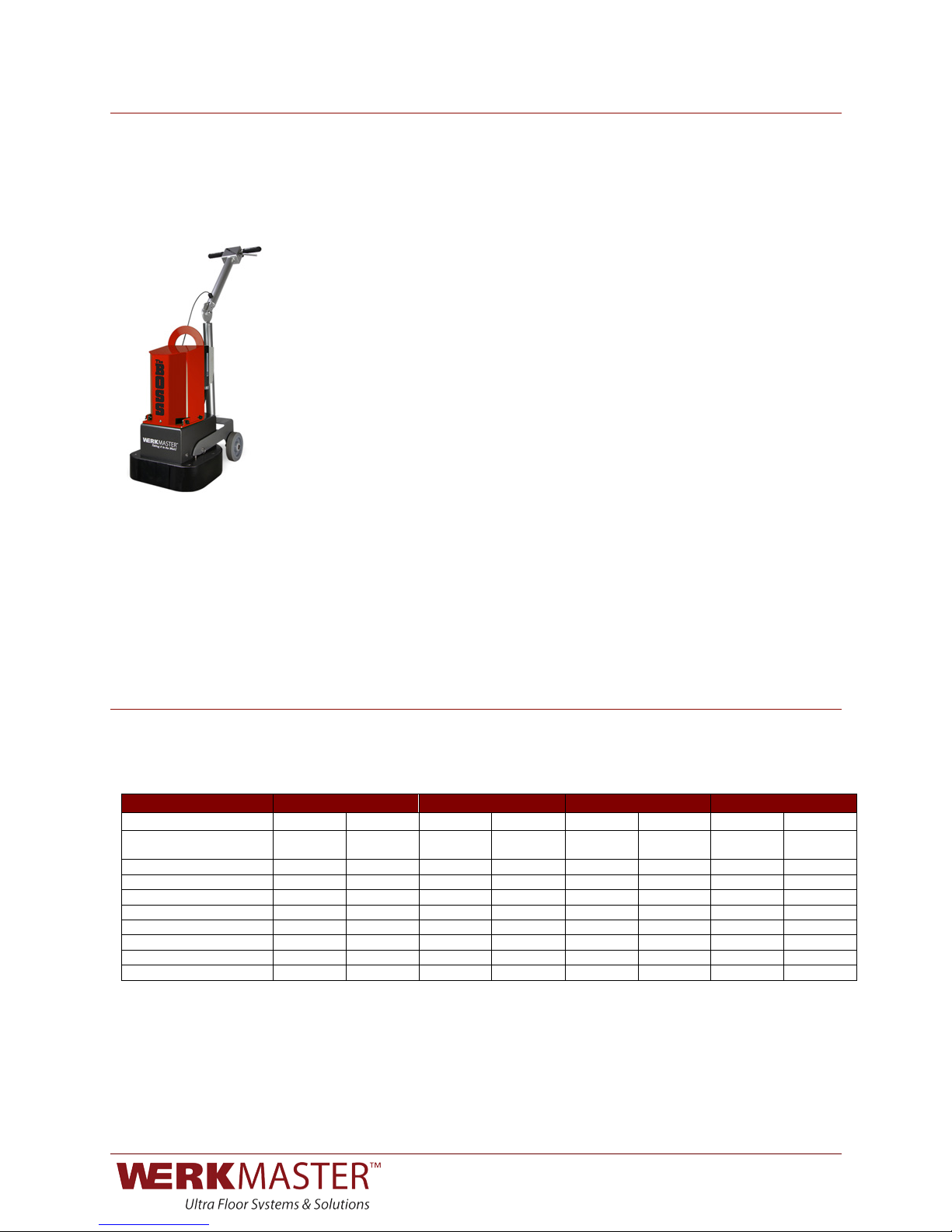
THE BOSS
•Multi-surface floor machine
•Designed to meet the needs of the rental market
•Use to prep concrete to safely removes thinset, VCT glue, carpet glue, epoxy
and paint; levels and preps uneven floors
•Use on hardwood and engineered hardwood to safely remove aluminum oxide
and other finishes
•Use to refinish wood decks
•Prep wood and other subfloors by removing thinset, VCT glue, carpet glue,
epoxy and paint
•Disassembles into three components for easy lifting and transport
•Lightweight and easy to maneuver
•Edges to within 1/8” (3 mm) of the wall
•Features 6 counter rotating heads and the versatility of using either our 5”
(127mm) ULTRA-FLEX full plate tools and sandpapers or the WerkMaster
Plug ‘N Go tooling system
•Variable frequency drive lets you run at speeds from 400 RPM to 700 RPM
•Runs using range or dryer outlet with Breakout Box (sold separately)
•Available with either 3HP 220V or 1.5 HP 110V motor
SPECIFICATIONS
!
!
MODEL
RASP
THE EDGE
MIROIR
THE BOSS
230V
110V
230V
110V
230V
110V
230V
110V
Dimensions: l x w in
l x w cm
14.5 x 14.5
37 x 37
14.5 x 14.5
37 x 37
14.5 x 14.5
37 x 37
14.5 x 14.5
37 x 37
14.5 x 14.5
37 x 37
14.5 x 14.5
37 x 37
14.5 x 14.5
37 x 37
14.5 x 14.5
37 x 37
Disc Size: in / cm
5 / 12.7
5 / 12.7
5 / 12.7
5 / 12.7
5 / 12.7
5 / 12.7
5 / 12.7
5 / 12.7
Weight: lb / kg
206 / 93.4
206 / 93.4
206 / 93.4
206 / 93.4
212 / 96.16
212 / 96.16
206 / 93.4
206 / 93.4
Disc Speed: RPM
400-1160
400-1160
400-1160
400-1160
400-1160
400-1160
400-700
400-700
Horsepower: HP
3
1.5
3
1.5
3
1.5
3
1.5
Phase: Ph
Single
Single
Single
Single
Single
Single
Single
Single
Vacuum Req: CFM
200
200
200
200
200
200
200
200
Min. Generator: kW
4.5+
2.0+
4.5+
2.0+
4.5+
2.0+
4.5+
2.0+
Frequency: Hz
50 / 60
50 / 60
50 / 60
50 / 60
50 / 60
50 / 60
50 / 60
50 / 60
!
!
!
!
!
!

0123!&!)
SAFETY PRECAUTIONS
)
Read this manual and all the safety precautions before attempting to
operate WerkMaster machines. Failure to follow the safety precautions may
result in severe personal injury or death. This product is intended for
commercial use.
•Wear eye and ear protection at all times when operating WerkMaster
machines. Use only ANSI/OSHA-approved safety glasses to help prevent
eye injury.
•Wear appropriate clothing and footwear when operating WerkMaster
machines. Do not wear loose clothing or jewelry that may become entangled
in moving parts.
•Exposure to wood dust may cause health problems. To reduce your risk, work
in a well-ventilated area, use a dust control system such as an industrial-
style vacuum, and wear approved personal safety equipment, such as a dust
or particle respirator designed to filter out microscopic particles.
•Crystalline silica from bricks and concrete and other masonry products may
cause health problems. To reduce your risk, work in a well-ventilated area,
use a dust control system such as an industrial-style vacuum, and wear
approved personal safety equipment, such as a dust or particle respirator
designed to filter out microscopic particles.
•NEVER operate WerkMaster machines under the influence of drugs or
alcohol, when taking medications that impair the senses or reactions, or
when excessively tired or under stress.
•Only operate and maintain WerkMaster machines if you are trained in their
use and are in good physical condition and mental health. You must be
physically able to handle their bulk, weight and power.
•WerkMaster machines are to be operated by one person at a time. Maintain a
safe operating distance from other personnel. Keep bystanders a safe
distance away during operation by blocking off the work area in all directions
with roping, safety netting, or other material. Failure to do so may result in
someone being injured by flying debris or being exposed to harmful dust and
noise.
•Maintain a safe operating distance from flammable materials. Sparks from the
cutting action of WerkMaster machines may ignite flammable materials or
vapors.
•Unplug the WerkMaster’s power cord when not in use and before servicing or
changing tooling plates.
•DO NOT disconnect power by pulling the cord. To disconnect power, grasp
the plug, not the cord. Push the plug in and turn clockwise to engage; turn
counter-clockwise and pull to remove.
•DO NOT turn on the WerkMaster while it is tilted back. Any tooling fastened to
the WerkMaster may eject and become a lethal projectile.
Personal Protective
Equipment
Physical and
Mental Fitness
Safe Operating Distance
Power
!!!!!!!!!!!!!!!!!!!!!!!!!!!!!!!!!! )WARNING)

0123!'!)
•Ground this floor-finishing machine while in use to protect the operator from
electric shock. The machine is provided with a three-conductor cord and a
three-contact grounding type attachment plug to fit the proper grounding type
receptacle. The green (or green and yellow) conductor in the cord is the
grounding wire. NEVER connect this wire to other than the grounding pin of
the attachment plug.
•Be sure all safety decals on the machine may be clearly read and understood.
Replace damaged or missing decals immediately.
•Maintain WerkMaster machines in safe operating condition with all guards in
place and secure, all mechanical fasteners tight, all controls in working
order, and the grinder configured for the job application, whether concrete,
natural stone, wood or other surfaces.
•To prevent damage to your machine or severe personal injury, avoid
protruding slab inserts, nails, screws, Hilti anchors, rebar, embedded bolts or
any other debris, pipe extensions, machinery bases, or any objects that
transmit sudden shock to the grinding assembly.
•Inspect the discs carefully before installing. DO NOT use any discs that exhibit
signs of damage, as severe personal injury or damage to the equipment
could result.
•NEVER leave WerkMaster machines running unattended.
•Risk of Explosion: Grinding/polishing concrete surfaces and sanding/finishing
wood floors can result in an explosive mixture of fine dust and air. Use this
machine only in well-ventilated area free from any flame, match or
combustible materials.
Dust generated from sanding wood floors can spontaneously ignite or
explode. Promptly dispose of any sanding dust in a metal container clear of
any combustibles. Do not dispose in a fire.
DO NOT modify WerkMaster machines. Modifications will void the warranty
and may result in injury to persons and damage to the machine.
POWER AND CONNECTIVITY
WerkMaster machines are outfitted with a variable-frequency drive (VFD) that
allows the desired grinding speed to be selected. Along with controlling the
speed of the machine, the VFD features include the following:
•Undervoltage protection (damages most single-phase motors)
•+/- 10% voltage protection
•60 Hz and 50 Hz capability (international)
•Wide voltage range for 230V models (200–230V)
•Soft start (smaller generator requirements)
•Monitor pad speed display
!
!
!
NEVER open the VFD panel while plugged in or immediately after
unplugging the power cord. Severe injury or death may result.
Safe Operating Conditions
Modifications
!!!!!!!!!!!!!!!!!!!!!!!!!!!!!!!!!! ))DANGER)

0123!(!)
WerkMaster machines come with a variety of different plug configurations. The
following table lists the plugs that are typically used.
!
!
!
!
!
!
WerkMaster machines come in a variety of voltage and phase configurations.
They are typically configured to operate on 208-230V single-phase power. They
are capable of operating on single-phase 208-230V power, as well as 110V
using a Breakout Box.
Pigtails are plug ends with unfinished bare wire on one end for hooking in to
panels. Pigtails are used when connectivity is unknown, when connecting to the
power grid of an unfinished building that has no power receptacles, or when
operating certain generators.
Certified electricians ONLY should make and/or install a pigtail in to a
panel.
When using the machines in a residential environment, source power may be
hard to find. Plug two 110V cords from the Quick 220 into the 110V wall outlet on
two (2) separate circuits on opposite sides of the panel. Plug the WerkMaster
machine into the Quick 220 adapter.
Draws power form either a stove/range or a dryer outlet and breaks it out into 2 x
20 Amp circuits that can be used to power both a WerkMaster machine and
auxiliary equipment such as a vacuum or the 110V Quad Box (sold separately).
The following table lists the requirements for power cords.
!
!
MODEL RASP THE EDGE MIROIR THE BOSS
Voltage
230V
110V
230V
110V
230V
110V
230V
110V
Breaker Size
20A
15A
20A
15A
20A
15A
20A
15A
Phase
Configuration
Single
Single
Single
Single
Single
Single
Single
Single
Cord End
3 pole
2 wire
20A
Twist Lock
Straight
blades
3 pole
2 wire
20A
Twist Lock
Straight
blades
3 pole
2 wire
20A
Twist Lock
Straight
blades
3 pole
2 wire
20A
Twist Lock
Straight
blades
General Connections
Adapter Cord
Pigtails
Quick 220 Adapter
Breakout Box
Power Cord
Minimum Requirements
MODEL RASP THE EDGE MIROIR THE BOSS
!
230V
110V
230V
110V
230V
110V
230V
110V
Max.
Distance
300 ft
50 ft
300 ft
50 ft
300 ft
50 ft
300 ft
50 ft
Min. Gauge
Requirement
12/3
14/3
12/3
14/3
12/3
14/3
12/3
14/3
!!!!!!!!!!!!!!!!!!!!!!!!!!!!!!!!!! ))DANGER)
0123!)!)
The minimum generator requirement for the 220V model is 4.5+ kW. The 110V
machine requires at minimum a 2.0+ generator.!
Exercise extreme caution at all times when working with electrical power.
WerkMaster strongly recommends that only certified electricians be permitted to
work with electrical power sources within customers’ facility or on their job site.
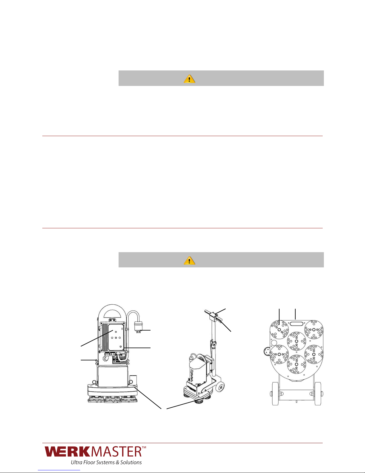
INTRODUCTION TO THE CONTROLS
!
The START button (A) is on the handle (Fig 2); the SPEED control (B) is on the
VFD (Fig 1).
The VFD controls are locked out to avoid accidentally changing necessary
parameters.
MACHINE OPERATION
!
)
)
ALWAYS turn off and disconnect power from the machine when performing any
operations to the bottom of the machine. The machine and the tooling may be
hot after using.
!!!!!!!!!!!!!
!!!!!!!!!!!!!!!!!!!! ! !!!!!!!!!!!!!!!!!!!!!!!!!!A)!!!!!!!!D))))))))))))M)
!
!!!!!!!!!!!!!!!!!!!!!!!!!!!!!!
!!!)))))))))))))))))
C))))))))))
))))))))))J)))))
))))))))
)I)))))))))B)))))
N))
)))))))))) )))))))))))))))
!!!!!!!!!!!!!!!!!
!!!))))))))))))))))))))))))
!
!
!
!!!!!L)))))))))) )
!
Generator
Minimum Requirements
Machine Controls
VFD Controls
!!!!!!!!!!!!!!!!!!!!!!!!!!!!!!!!!! )WARNING)
!!!!!!!!!!!!!!!!!!!!!!!!!!!!!!!!!! )WARNING)
0123!*!)
!!!!!!Fig. 1 Fig. 2 Fig. 3
A
!
!!!!!))))))))
!!!!!!!!!!!!J)
5)
!
!
!!!!!!!!!!!H)
6)
!!!!!!!!!!!!!!!G)
!
!!!!!!!!!!!!!!!!K)
D)
!!!!!!!!!!!!!)
!
!!!!!!Fig. 4 Fig. 5 Fig. 6
!
!
!
!
!
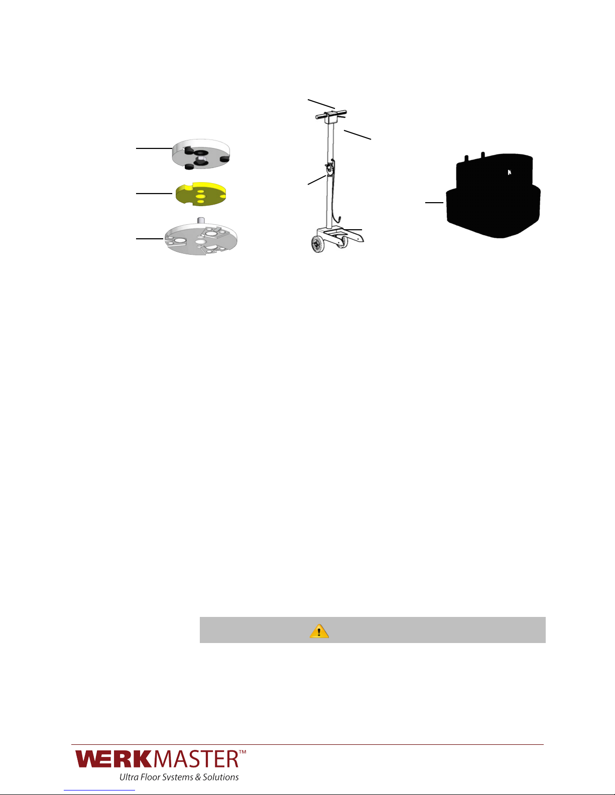
To change tooling:
1. Unplug the power cord from the twist lock plug (C). Ensure the handle is in its
full upright position (Fig 2). Tilt the machine back (Fig 3). Choose the
appropriate tooling holder attachment – magnetic Plug ‘N Go plate (D) for
Metal Bond tools or Foam Hook and Loop Adapter plate for polishing resins
and sandpaper. Insert the 2 shear pins through the compression foam pad
(E) into the rubber grommets on the pad driver (F). Attach the corresponding
tooling to the plate.
2. Return the machine to the upright position (Fig 2).
!
!
The dust skirt (G) serves as a seal for the bottom of the machine to act as a
vacuum chamber helping the dust stay contained under the machine. If the skirt
is too far from the ground, the dust containment is reduced.
To adjust the skirt:
1. Pull one end of the skirt off the machine until you reach the middle of the skirt.
2. Position the skirt until it is barely touching the ground and repeat with the other
end.
3. Pull the skirt snug. The two ends of the skirt should not touch. You may have a
gap of up to ½inch. Using the fabric connector cover the gap.
!
Avoid positioning the skirt too low as it will drag against the ground, wearing the
skirt out prematurely and possibly preventing smooth machine movement.
!
!
!
!
Changing Tools
)
Adjusting the Dust Skirt
!!!!!!!!!!!!!!!!!!!!!!!!!!!!!!!!!! ))CAUTION)

0123!+!)
To adjust the handle, pull the pin (H). Adjust the handle to a comfortable
operating position. Release the pull pin and allow it to click into the positioning
hole.
!
!
!
Failure to check the pull pin is fully engaged could result in damage to the
machine or personal injury as the handle could release unexpectedly when the
machine is being operated or tilted back.
!
!
When the machine is first plugged in, a start-up screen (I) will flash STOP.
To start the machine, gently squeeze the activation lever (J) and press and
release the START button (A).
DO NOT lift the machine off the ground while starting it. Doing so could
cause the diamonds to release from the machine, resulting in damage to the floor
or personal injury.
The speed of the machine can be adjusted when the machine is running or
stopped. To adjust the speed, rotate the speed control knob (B) on the VFD
clockwise to speed it up, or counterclockwise to slow it down. Always start the
machine at the lowest speed and adjust as necessary.
Once the machine reaches the desired speed, the speed will remain constant as
long as the load applied remains below 100%. If the machine is running at speed
and the load begins to exceed 100%, the machine will reduce its speed as a
protective measure to try and alleviate the outstanding load. The current running
speed will be displayed. This happens under demanding conditions and is
normal.
If the machine is not able to maintain the minimum speed for more than 30
seconds the machine will turn off. This is a normal protective measure. To
prevent this from reoccurring alleviate some of the load and then resume
operation.
!
!
Let go of the activation lever.
When you unplug the machine, the screen will stay lit for a few seconds as the
VFD drains the power from its internal capacitors. This is normal.
!
)
)
)
NEVER open the VFD panel while plugged in or immediately after
unplugging the power cord. Severe injury or death may result.
!
!
Adjusting the Handle
Initial Start Sequence
Starting the Machine
Adjusting the Speed
Stopping the Machine
!!!!!!!!!!!!!!!!!!!!!!!!!!!!!!!!!! )WARNING)
!!!!!!!!!!!!!!!!!!!!!!!!!!!!!!!!!! ))DANGER)
!!!!!!!!!!!!!!!!!!!!!!!!!!!!!!!!!! )WARNING)

0123!,-!)
To install and remove the pad driver on the bottom of the machine, you will need
a 17 mm socket wrench, a soft face mallet, and some medium-strength thread
locker (blue Loctite 243 or equivalent).
To remove the pad driver:
1. Slip the 17 mm socket wrench over the pad driver bolt and strike the wrench
with the soft face mallet in a counter-clockwise direction.
2. When installing a new pad driver or re-installing an existing one, apply a
generous amount of thread locker compound to the bolt and the threaded
drive shaft. Insert the bolt through the hole in the pad driver. Reapply thread
locking compound every time a pad driver is removed.
3. Line up the bolt to the threaded end of the shaft and start the first couple of
threads.
4. Once the bolt is engaged, make sure that the drive shaft is properly seated
within the pad driver slot before tightening the bolt all the way.
!
!
!
Failure to seat the pad driver could result in the pad driver slot being damaged,
the threads in the shaft being stripped, the machine leaving heavy tool marks,
and the tooling overheating.
!
Discs 1, 2, and 3 rotate
clockwise
!
!
!
!
Discs 4, 5, and 6 rotate
counter-clockwise
!
!
!
!
!
78998:!8;!<3=>?1@93=!AB9C!DE:F3=3G!988HBD2!IH193@!1DG!JH8J>AB@3!1DG!J8ED93=JH8J>AB@3!H1F3HBD2%!
!
!
!
!
!
!
!
!
!
!
!
!
!
!
Installing and Removing
the Pad Driver
Rotation Pattern of
Tooling Plates
!!!!!!!!!!!!!!!!!!!!!!!!!!!!!!!!!! ))CAUTION)

0123!,,!)
!
Motor Mount Assembly Handle
Motor Mount Assembly
Motor Shaft
Thumbscrews
Primary Driven Housing
Primary Driven Sprocket
Motor Coupling
Primary Belt
Belt Tensioner
Pull Pin
Cover Plate
Cover Plate Gasket
Flanged Bearing Drive Train Top Plate
Secondary Belt
Sprockets
Drive Train Gasket
Drive Train Bottom Plate
M8 Flat Socket Screws
Water Baffles (MIROIR only)
Baffle Screws (MIROIR only)
Fig. 7
Changing the Primary
Belt

0123!,/!)
To change the Primary Belt:
1. Disconnect the power and ensure the handle is in the upright position.
2. Unscrew the handle control cable (K) (Fig 5) from the VFD.
3. Remove the pull pins from each handle arm (L) (Fig 2) and roll the handle
assembly away from the machine.
4. Remove the four thumbscrews (Fig 7) from the motor mounting assembly.
5. Use the handle in the motor mounting assembly to lift the motor mounting
assembly straight up until the motor shaft is completely clear of the base.
6. Remove the four M10 flat socket cap screws on the primary driven housing
exposing the primary belt.
7. Loosen the four M8 hex head bolts and the M10 hex head bolt on the belt
tensioner and slide forward to relieve tension.
8. Remove and replace the belt.
9. Tighten the M10 hex head bolt on the belt tensioner so that the belt tension
is 30 in/lb then tighten the four M8 hex head bolts.
10. Replace the primary housing and then replace the four M10 flat socket cap
screws on the primary housing.
11. Lower the motor mounting assembly onto the motor shaft making sure to
line up the motor coupling with the drive shaft.
12. Replace the four thumbscrews in the motor mounting assembly.
13. Roll the handle assembly back into place and reconnect the handle arms by
pushing the pull pins through the holes and into the base.
14. Reconnect the handle control cable in the VFD.
Jack Points
Secondary Belt Path
Fig. 8 Fig. 9
To change the secondary belt:
1. Disconnect power and ensure the handle is in the upright position.
2. Tilt the machine back (Fig 3).
3. Remove the Plug ‘N Go plates and pad drivers.
4. MIROIR only: Remove the water baffles.
5. Remove the thirteen M8 flat socket screws from the drive train bottom (Fig
8).
6. Insert six long M8 screws into the jack point threaded holes until snug.
7. Make a half turn of each screw clockwise until the drive train plates start to
separate.
8. Separate the drive train top plate from the drive train bottom plate exposing
the sprockets and belts. Remove the jack point screws.
9. Remove the gasket.
10. Remove the broken/damaged belt.
11. Replace the belt (Fig 9).
NOTE: Removing one sprocket and the shaft assembly may make the belt
installation easier,
12. Replace the gasket.
Changing the Secondary
Belt

0123!,4!)
13. Carefully line up the bottom plate with the shafts.
14. Apply Anti-Seize on the long M8 screws.
15. Thread five of the long M8 screws through the bottom plate at the four
corners and one near the center.
16. Slowly and evenly make a half turn of each screw in a clockwise direction
until all the shafts are lined up with the bottom plate.
17. Thread in all the remaining M8 screws and in a clockwise direction slowly
clamp the drive train plates together.
18. Tighten each M8 screw to 150 in/lbs.
19. MIROIR only: Replace the water baffles and apply blue Loctite to all water
baffle fasteners.
20. ALL OTHER MODELS: Apply blue Loctite to the four short jack point screws
and replace.
NOTE: Replace all gaskets every time the gaskets are removed or the
Drive Train is opened.
VACUUM PORT
!
For the RASP, The EDGE, the MIROIR, and The BOSS:
The vacuum recommended for all machines has a minimum CFM OF 200.
1. ALWAYS run vacuum when sanding or grinding.
2. The vacuum port accepts a standard 2” vacuum hose cuff.
3. Always refer to vacuum manual.
NOTE: ONLY use a wet/dry vacuum with the MIROIR.
!
WATER FEATURE
The MIROIR is equipped with a water feature.
A
B
To use the water feature:
C
1. Ensure the flow control valve is closed (B).
2. Fill the water tank (A).
3. Insert water feature plug into the vacuum port (C).
4. Slowly open the flow control valve to the desired water flow and close as
required.
5. Operate machine normally.
Use extreme caution when working with electricity and water. Severe injury
or death may occur if caution is not used.
!!!!!!!!!!!!!!!!!!!!!!!!!!!!!!!!!! ))DANGER)

0123!,&!)
DISASSEMBLY / ASSEMBLY INSTRUCTIONS
To disassemble:
1. Disconnect power.
2. Unscrew handle control cable (K) from VFD (Fig 5 on p 8)
3. Remove pull pins (L) from each handle arm and roll handle assembly away
from machine (Fig 2 on p 7).
4. Remove the four thumbscrews (N) from the motor mounting assembly.
5. Use handle in the motor mounting assembly to lift the motor mounting
assembly straight up until motor shaft is completely clear of the base.
6. Located on the bottom of the base is a recessed handle (M) (Fig 3 on p 7) for
carrying the base.
To assemble:
1. Lower the motor mounting assembly onto the motor shaft making sure to line
up the motor coupling with the drive shaft.
2. Replace the four thumbscrews in the motor mounting assembly.
3. Roll the handle assembly back into place and reconnect the handle arms by
pushing the pull pins through the holes and into the base.
4. Reconnect the handle control cable in the VFD.
'% Connect to power.!
!
!
!
!
!
!
!
!
!
!
!
!
!
!
!
!
!
!
!
!
!
!
!
!
!
!
!
!
!

0123!,'!)
MAINTENANCE
!
!
Disconnect power before performing any maintenance, cleaning, or repair
to your machine.
After wet operation, wash bottom of the machine thoroughly, failure to do
so may result in damaged bearing seals.
Do not use any sharp object or abrasive pad to clean the bearing seals.
This can compromise the bearing seals.
•Wipe down the machine after every job.
•Gently remove dirt and debris from the pad driver.
•Check to ensure the pad driver bolts are tight. If loose, remove pad driver and
apply blue thread locker (Locktite 243).
•Check grommets and replace if necessary.
•Vacuum, wash and thoroughly dry the underside of the machine.
•Inspect the plug ends for signs of carbon deposits and arcing.
•Check all fasteners and tighten if necessary.
•Inspect bearings seals around shaft for any wear or damage.
•Inspect the handle wires for damage.
•Blow off the VFD heat sink with compressed air.
•Using a soft scrub pad, remove any excess dirt build-up from the bottom plate
and back side of the pad drivers.
•Check all strain reliefs and make sure they are tight. (Strain reliefs are the
plastic nuts that secure the wires that come out of the handle and VFD.)
•Clean and lubricate wheels.
•Using an extremely light abrasive pad, remove any topical rust from the shafts.
Daily
Weekly
Monthly
!!!!!!!!!!!!!!!!!!!!!!!!!!!!!!!!!! )WARNING)
!!!!!!!!!!!!!!!!!!!!!!!!!!!!!!!!!! ))CAUTION)

0123!,(!)
TROUBLESHOOTING )
!
ISSUE)
TEST!
SOLUTIONS!
?1JCBD3!ABHH!D89!9E=D!8D%!
KC3J>!1HH!I8A3=!J8DD3J9B8D@%!?1>3!@E=3!
9C3!@8E=J3!I8A3=!:339@!9C3!:1JCBD3L@!
:BDB:E:!I8A3=!=3MEB=3:3D9@!N@33!
Power&Cord&Minimum&Requirements&&p.&5O%!
•0HE2!BD!9C3!:1JCBD3%!
•KC3J>!98!@33!B;!1DP!F=31>3=@!8=!;E@3@!1=3!9=BII3G!8=!FH8AD%!
•KC3J>!98!@33!9C3!C1DGH3!1J9BQ19B8D!H3Q3=!B@!D89!G3I=3@@3G%!
•R1Q3!1!ME1HB;B3G!3H3J9=BJB1D!93@9!9C3!@8E=J3!I8A3=!98!@33!B;!B9!:339@!
9C3!:1JCBD3L@!:BDB:E:!I8A3=!=3MEB=3:3D9@%!!
•0=3@@!ST$UT!FE998D!ACBH3!1J9BQ19B8D!H3Q3=!B@!G3I=3@@3G%!
V5W!9E=D@!8D!FE9!:1JCBD3!
ABHH!D89!@91=9%!
KC3J>!9C3!V5W!GB@IH1P!;8=!3==8=!J8G3@!
Nsee&Appendix&p.&14O%!!
•#;!D8!3==8=!J8G3!B@!GB@IH1P3GX!JC3J>!B;!9C3!J8D9=8H!J1FH3!B@!IHE223G!
BD98!9C3!:1JCBD3%!!
•#;!9C3!V5W!3==8=!J8G3!B@!YH8A!Q8H9123Z!C1Q3!1!ME1HB;B3G!3H3J9=BJB1D!
93@9!9C3!@8E=J3!I8A3=!1DG!:1>3!9C3!D3J3@@1=P!1G[E@9:3D9@!98!
9C3!AB=BD2!98!@EIIHP!9C3!:1JCBD3!AB9C!B9@!=3MEB=3G!BDIE9!I8A3=%!
?1JCBD3!=ED@!;8=!1!@C8=9!9B:3!
1DG!9C3D!@CE9@!G8AD%!
KC3J>!9C3!JB=JEB9!F=31>3=!98!@33!B;!B9!B@!
9=BII3G!8=!9C3!;E@3!B;!B9!B@!FH8AD%!
•KC3J>!98!:1>3!@E=3!9C19!9C3!I8A3=!@8E=J3!C1@!9C3!1II=8I=B193HP!
@B\3G!F=31>3=!8=!;E@3!98!:339!9C3!:1JCBD3L@!:BDB:E:!I8A3=!
=3MEB=3:3D9@%!!
•?1>3!@E=3!9C3!23D3=198=!:339@!9C3!:1JCBD3L@!:BDB:E:!I8A3=!
=3MEB=3:3D9@%!!
•R1Q3!1D!3H3J9=BJB1D!I3=;8=:!1!Q8H9123!93@9!ACBH3!9C3!:1JCBD3!B@!
EDG3=!H81G!98!@33!B;!9C3!Q8H9123!G=8I@!F3H8A!9C3!:1JCBD3L@!
:BDB:E:!I8A3=!=3MEB=3:3D9@%!
01G!G=BQ3=@!1=3!D89!9E=DBD2!8=!
8DHP!8D3!I1G!G=BQ3=!B@!
9E=DBD2%!
WB@J8DD3J9!9C3!I8A3=!1DG!9BH9!9C3!
:1JCBD3!F1J>%!SIBD!8D3!I1G!FP!C1DG%!!
•#;!9C3!I1G!9E=D@!BDG3I3DG3D9HPX!=3IH1J3!9C3!@3J8DG1=P!F3H9%!]8!98!
AAA%A3=>:1@93=%J8:^@EII8=9%!
•#;!1HH!I1G!G=BQ3=@!9E=D!FE9!9C3!:898=!;1D!G83@!D89!9E=DX!=3IH1J3!9C3!
I=B:1=P!F3H9%!S33!U3I1B=!_!?1BD93D1DJ3!QBG38@!19!AAA%!
<3=>:1@93=%J8:%!
`89!1HH!GB@J@!1=3!2=BDGBD2!9C3!
;H88=%!
WB@J8DD3J9!9C3!I8A3=!1DG!9BH9!9C3!
:1JCBD3!F1J>%!VB@E1HHP!BD@I3J9!31JC!I1G!
G=BQ3=!C3B2C9!121BD@9!9C3!1G[1J3D9!I1G!
G=BQ3=%!
•?1>3!@E=3!1HH!I1G!G=BQ3=@!1=3!@3193G!I=8I3=HP!8D!9C3!@C1;9@%!!
•?1>3!@E=3!2=BDGBD2!^!I8HB@CBD2!^!@1DGBD2!:3GB1!B@!@3193G!I=8I3=HP!
8D!9C3!I1G!G=BQ3=@%!
•?1>3!@E=3!2=BDGBD2!^!I8HB@CBD2!^!@1DGBD2!:3GB1!B@!A8=D!3Q3DHP!1DG!
JC1D23!8E9!1DP!:3GB1!B;!ED3Q3D%!
•?1>3!@E=3!J8:I=3@@B8D!;81:@!1=3!I8@B9B8D3G!1=8EDG!9C3!FE:I3=@!
6aJ3@@BQ3!D8B@3!8=!QBF=19B8D!B@!
;3H9!8=!C31=G!ACBH3!=EDDBD2!
9C3!:1JCBD3%!
WB@J8DD3J9!9C3!I8A3=!1DG!9BH9!9C3!
:1JCBD3!F1J>%!SIBD!8D3!I1G!FP!C1DG%!
"B@93D!;8=!1!JHBJ>BD2!@8EDG!8=!2=B9bHB>3!
;33HBD2%!
•KC3J>!9C19!1HH!988HBD2!B@!BD!9C3!J8==3J9!IBD!C8H3@!8D!9C3!I1G!G=BQ3=@%!
•U3IH1J3!9C3!F31=BD2@%!K8D91J9!93JCDBJ1H!@EII8=9c!*((b4)4b+4)'!;8=!
BD@9=EJ9B8D@%!
T88HBD2!F3J8:3@!GB@H8G23G!
;=8:!9C3!:1JCBD3!ACBH3!
8I3=19BD2%!
WB@J8DD3J9!9C3!I8A3=!1DG!9BH9!9C3!
:1JCBD3!F1J>%!U3:8Q3!1DG!BD@I3J9!1HH!
988HBD2%!TCB@!BDJHEG3@!9C3!IBD@X!988HBD2!
IH193@X!1DG!I1G!G=BQ3=@%!
•#;!9C3!IBD!C8H3@!1=3!3aJ3@@BQ3HP!G1:123GX!=3IH1J3!9C3!I1G!G=BQ3=@%!
•#;!9C3!2=8::39@^FE:I3=@!8D!9C3!I1G!G=BQ3=@!1=3!G1:123GX!=3IH1J3!
9C3!G1:123G!I1=9@%!
•#;!9C3!IBD@!8D!9C3!GB1:8DG@!8=!988HBD2!IH193@!1=3!G1:123G!8=!
:B@@BD2X!=3IH1J3!9C3!IBD@%!
TC3!:1JCBD3!C1DGH3!
:1H;EDJ9B8D@%!!
KC3J>!9C3!C1DGH3!IHE2!98!@33!B;!B9!C1@!
J8:3!H88@3%!
•S3JE=3!9C3!C1DGH3!IHE2%!#;!9C3!C1DGH3!J8D9=8H@!1=3!@9BHH!
:1H;EDJ9B8DBD2X!J8D91J9!JE@98:3=!@3=QBJ3!;8=!BD@9=EJ9B8D@%!
V5W!:1>3@!I8IIBD2!D8B@3!
1DG!@91=9@!98!@:8>3%!
***Disconnect)power)
immediately!***!
<1B9!;8=!,d/!C8E=@X!9C3D!=3:8Q3!9C3!V5W!
J8Q3=!1DG!JC3J>!3H3J9=8DBJ!J8:I8D3D9@!
;8=!GB@J8H8=19B8DX!@J8=JCBD2X!8=!@A3HHBD2%!
•K8D91J9!1!G31H3=!8=!93JCDBJ1H!@EII8=9c!*((%4)4%+4)'%!
V5W!@J=33D!GB@IH1P@!3==8=!
:3@@123!8=!EDE@E1H!@J=33D!
GB@IH1P%!
"88>!EI!9C3!:3@@123!BD!9C3!$II3DGBa%!
•K8D91J9!93JCDBJ1H!@EII8=9c!*((%4)4%+4)'%!

0123!,)!)
APPENDIX – KBDA VFD TROUBLESHOOTING AND DIAGNOSTICS
!!
The following table shows the 4-digit display readout of drive status, operating
parameters, and faults.
!
!
!
!
DO NOT depend on the LEDs or the 4-Digit Display to no longer be illuminated
as a guaranteed POWER OFF condition. Be sure the main power switch or
circuit breaker is in the OFF position BEFORE servicing the drive.
DISPLAY
DESCRIPTION
DISPLAY
DESCRIPTION
!
StoP
Drive Stopped – Indicates that the
drive is in Stop Mode. Function No.
4.03 set to “0001.”!
!
Err2
Keypad Communication Error –
Indicates that the keypad failed to
initialize when the drive is powered up.
This is an abnormal condition -
!
–LU–
Low Voltage Trip – Indicates that
the AC line input voltage is below
the Undervoltage Trip Point.!
Err4
IODA Error – Indicates that the drive has
lost communication with the IODA.
!
–OU–!
Overvoltage Trip – Indicates that
the AC line input voltage is above
the Overvoltage Trip Point.!
!
–SC–!
Short Circuit Fault – Indicates that the
drive
detected a short circuit at the
motor (phase-
to-phase).
!
OL–t
Overload Trip (l2t Timeout) –
Indicates that the motor has been
overloaded for an extended period
of time.!
!
Err1
Data Enter Error – Indicates that
the drive is
in the Program Mode
and a non-valid
parameter change
has been attempted.
!
CS–t
Current Source Trip – Indicates
that the current signal output (from
the IODA) has been opened.!
!
Err3!
Flash)Memory)Error)–)#DGBJ193@!9C19!1!;H1@C
!
:3:8=P!3==8=!8D!9C3!G=BQ3!C1@!8JJE==3G%!
TCB@!B@!1D!1FD8=:1H!J8DGB9B8D!d!J8D91J9!!
<3=>?1@93=!T3JCDBJ1H!SEII8=9!at ,b(-&b
(/+b*)--%
!
!
–PL–!
AC Line Phase Loss Detection –
Indicates that the drive has
detected a loss of one of the
phases.
!
!
!
!
!
!
!
!
!
!
!
!
!!!!!!!!!!!!!!!!!!!!!!!!!!!!!!!!!!! )))))WARNING)
Digital Readout Codes
This manual suits for next models
4
Table of contents
Other WerkMaster Floor Machine manuals


Popular Floor Machine manuals by other brands

Nobles
Nobles Speed Scrub 2001HD Operator and parts manual

Advance acoustic
Advance acoustic Terra 3700B Service manual

Monaghan
Monaghan ELLIOTT Installation and operating instructions

Columbus
Columbus ARA 80 BM 150 operating manual

Nilfisk-Advance
Nilfisk-Advance SD 17 Instructions for use

BETCO
BETCO WS24 manual

Eureka
Eureka E46 Series instruction manual

Diamatic
Diamatic BGS-250 operating instructions

Triple S
Triple S Cheetan 1500 owner's manual

Minuteman
Minuteman Rush 100 Cold Parts and instruction manual

Tennant
Tennant SweepSmart S20 ELECTRIC Operator's manual

Mytee
Mytee Mytee-Lite II 8020 User and parts manual


