WERMA Signaltechnik KombiSIGN 71 User manual

Manual USB Terminal Element
WERMA Signaltechnik GmbH + Co. KG
Manual for USB Terminal Element KombiSIGN 71 and
KOMPAKT 71 with USB Interface
Version 2.2. – 2014


Version 2.2 - 0514 3
Contents
Contents ........................................................................................................................................................... 3
1. Introduction ........................................................................................................................................... 4
2. Technical information........................................................................................................................... 5
2.1 Assembly .........................................................................................................................................5
2.1.1 Terminal Element with USB interface (640.840.00)........................................................5
2.1.2 Kompakt 71 with USB interface (697.430.53) .................................................................5
2.2 System requirements.....................................................................................................................5
2.3 Safety instructions..........................................................................................................................6
2.4 Technical data...............................................................................................................................7
3. Automatic Driver Installation ............................................................................................................... 7
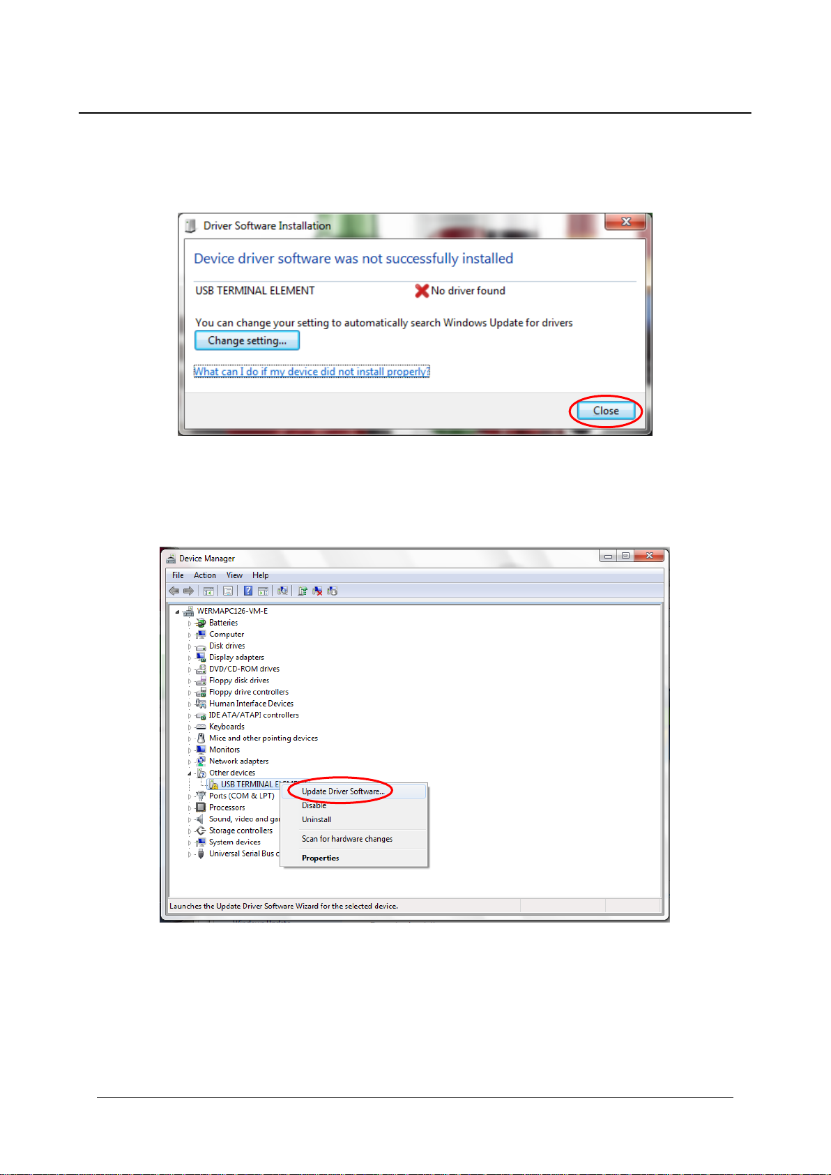
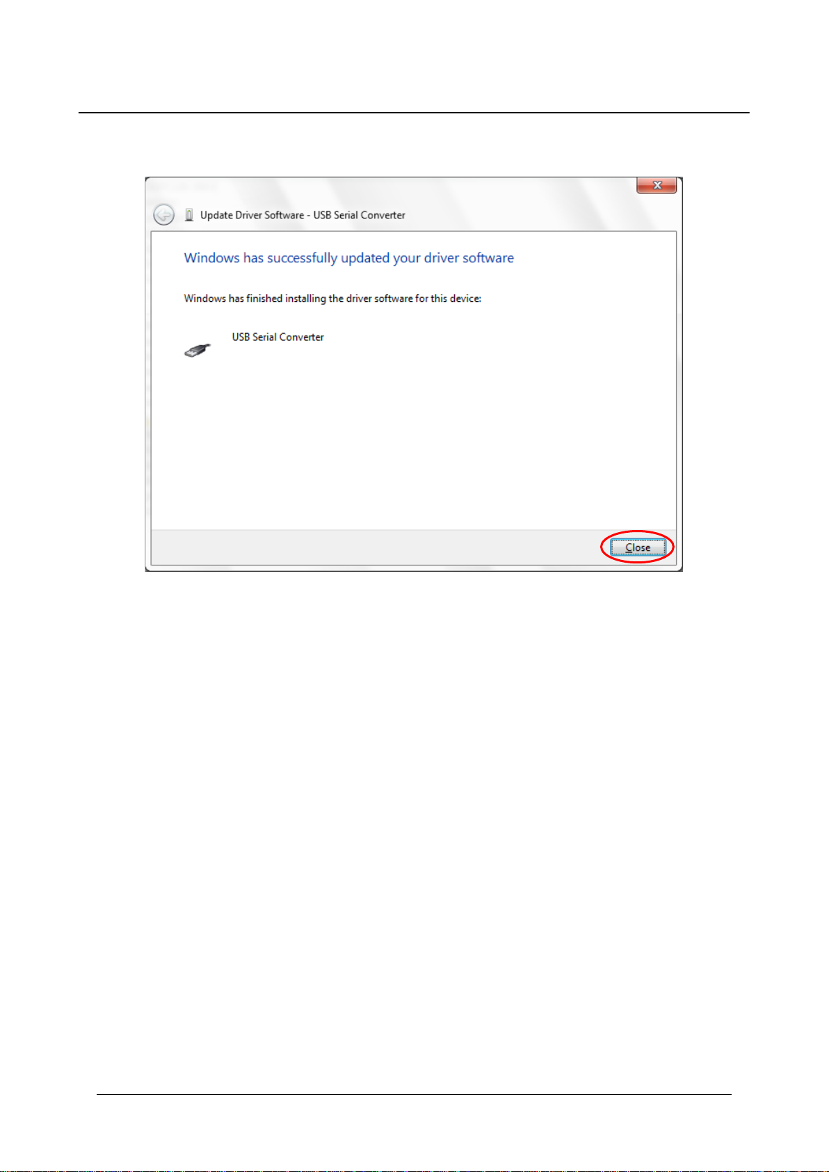
4. Manual driver installation..................................................................................................................... 8
5. Operation with COM Port................................................................................................................... 11
5.1 Settings ..........................................................................................................................................11
5.2 Commands...................................................................................................................................11
5.2.1 Version ................................................................................................................................11
5.2.2 Name ..................................................................................................................................11
5.2.3 Write ....................................................................................................................................12
5.2.4 Read....................................................................................................................................13
5.3 HyperTerminal ..............................................................................................................................13
6. Operation with Dynamic Link Library (DLL)...................................................................................... 16
6.1 Introduction..................................................................................................................................16
6.2 Related files and executables..................................................................................................16
Runtime files:.................................................................................................................................16
6.3 DLL Functions................................................................................................................................16
6.3.1 Function Overview............................................................................................................16
6.3.2 Basic Functions..................................................................................................................17
6.3.2.1 SetUsbDevice........................................................................................................17
6.3.2.2 SetDeviceStatus...................................................................................................17
6.3.2.3 GetDeviceStatus..................................................................................................18
6.3.2.4 GetDeviceSerial...................................................................................................19
6.3.2.5 GetDeviceLocation.............................................................................................19
6.3.2.6 GetFirmwareVersion............................................................................................20
6.3.2.7 GetLibVersion .......................................................................................................20
6.3.3 Further Functions...............................................................................................................21
6.3.3.1 SetIOStatus............................................................................................................21
6.3.3.2 SetSingleIO............................................................................................................21
6.3.3.3 GetIOStatus...........................................................................................................22
6.3.3.4 GetSingleIO...........................................................................................................23
7. USB Terminal Element Demo.............................................................................................................. 24

4
1. Introduction
Many applications require faults or the operating status to be displayed by an optical signal.
As a PLC or machine control system is not always available, PCs are frequently used for
system control and monitoring.
The ideal solution here is to use the terminal element with USB interface, which is available for
both signal tower series KombiSIGN 71 and Kompakt 71. Developed in-house at WERMA, this
innovative product allows direct PC actuation for fast and convenient commissioning. As well
as actuation via a DLL (Dynamic Link Library), the element can also be simply commissioned
by means of VCP (Virtual COM Port) actuation. This ensures for simple integration into any
customer-specific software.
Up to five signal towers with a maximum of five signalling elements each can be connected
per PC. An optimized electronic circuit allows each of the elements to be triggered either as
a permanent or blinking light. This means that up to ten different operating statuses can be
signalled using only a single signalling tower. The terminal element with USB interface requires
neither its own separate power supply nor any additional hardware.
WERMA Signaltechnik GmbH + Co.KG
D-78604 Rietheim-Weilheim
Fon: +49 (0)7424 / 9557-0
Fax: +49 (0)7424 / 9557-44
info@werma.com
www.werma.com
As of: 05/2014
310.640.008

Version 2.2 - 0514 5
2. Technical information
2.1 Assembly
2.1.1 Terminal Element with USB interface (640.840.00)
Description
Quantity
USB terminal element
1
USB cable 1.8 m
1
Software CD
1
Instruction leaflet
1
2.1.2 Kompakt 71 with USB interface (697.430.53)
Description
Quantity
Pre-assembled tower (red/yellow/green) with USB terminal element
1
USB cable 1.8 m
1
Software CD
1
Instruction leaflet
1
2.2 System requirements
-500 MHz Pentium II processor or higher
-256 MB RAM (512 MB is recommended)
-150 MB free hard disk space
-CD/DVD drive
-USB port
-Windows 2000 service pack 4, Windows XP, Windows Vista, Windows 7 or Windows 8
-Windows Server 2000 service Pack 4, Windows Server 2003, Windows Server 2008,
Windows Server 2008 R2
-Windows Installer 3.1

6
2.3 Safety instructions
Caution!
-Please also refer to the instruction leaflet for your WERMA signal tower.
-The USB terminal element is not suitable for safety critical applications.
-For use with 24 V WERMA signal elements with max. 90 mA.
KOMPAKT 71

Version 2.2 - 0514 7
2.4 Technical data
Operating voltage
5 V DC (USB)
Output voltage
24 V DC (+/- 10 %)
Current consumption
Typ. 500 mA
Output current
Max. 90 mA
Min. operating temperature
- 25 °C
Typ. operating temperature
+ 25 °C
Max. operating temperature
+ 60 °C
The signal tower elements can be triggered directly from a PC or Laptop via a standard USB
interface. The USB port must deliver min. 500 mA, if not a USB-Hub with external power supply
must be used.
3. Automatic Driver Installation
Insert the USB terminal element CD and install the file Setup_Win_2k_XP_Vista_7. This setup
installs the drivers for Windows 2000, Windows XP, Windows Vista, Windows 7 and Windows 8.
Note: You must have administrator rights to install the drivers.

8
4. Manual driver installation
Note: Manual driver installation is only required if the USB terminal element is not recognised.
Windows will open the following window.
Close this window and open the Device Manager (Computer/Properties/Device Manager).
Click with the right mouse button on USB TERMINAL ELEMENNT and then click on “Update
Driver Software”.

Version 2.2 - 0514 9
Select “Brows my computer for driver software” and insert the CD of the USB terminal element
into your CD-ROM drive.
Specify the location of the driver by clicking “Browse”. Select the “Driver” folder in the CD-
ROM drive and confirm by clicking “Next”.

10
The driver for the USB terminal element has been successfully installed. Click “Close” to finish
the update.
Note: The USB terminal element is now ready for operation.

Version 2.2 - 0514 11
5. Operation with COM Port
5.1 Settings
For the COM port you need the following settings:
Baud rate
9600 bits per second
Data bits
8
Stop bit
1
Parity
None
Flow control
No
5.2 Commands
Note: Every command has to end with a return or line feed.
5.2.1 Version
Type
Command
Description
Version
V
Information about the version.
V<CR>
Return
Information of the version
Example:
V<CR> Version:1.2.0
5.2.2 Name
Type
Command
Description
Name
N
Information about the name.
N<CR>
Return
Information of the name
Example:
N<CR> USB TERMINAL ELEMENT

12
5.2.3 Write
Type
Command
Description
Write
WRXXXXX
Sets the output, X could be:
0 Off
1 On
2 Blinking mode 1
3 Blinking mode 2
X Don’t care, no change on that tier
WRXXXXX<CR>
Return
Tier 5
Tier 4
Tier 3
Tier 2
Tier 1
Write
Example:
WR120X3<CR> OK (Tier 1: On; Tier 2: Blinking mode 1; Tier 3: Off;
Tier 4: Don’t care; Tier 5: Blinking mode 2)
Note: Blinking mode1 and Blinking mode 2 differ by blinking alternately (see diagram).
ON
OFF
Permanent
ON
OFF
Blinking mode 1
ON
OFF
Blinking mode 2
Time

Version 2.2 - 0514 13
5.2.4 Read
Type
Command
Description
Read
RD
Information of current status.
RD<CR>
Return
Information of status
Example:
RD<CR> 02131 (Tier 1: Off; Tier 2: Blinking mode 1; Tier 3: On;
Tier 4: Blinking mode 2; Tier 5: On)
5.3 HyperTerminal
Windows HyperTerminal or a comparable Linux application shows how the USB terminal
element can be triggered. Using the same settings, the USB terminal element can be
triggered from other applications.
Note: As of Windows Vista, HyperTerminal is no longer included. But you can download this
free from the Internet or use another terminal program.
Example with HyperTerminal:
1. Connect the USB terminal element to a USB port on your computer.
2. Start the HyperTerminal: Start/Programs/Accessories/Communication/HyperTerminal
3. Enter a name in the first window (e.g. WERMA USB terminal element)

14
4. Now select the corresponding port (e.g. COM6)
5. Set the bits per second in the following window to 9600 and flow control to none.
6. Open the Properties File/Properties and the register Settings and press the button
“ASCII Setup”.

Version 2.2 - 0514 15
7. Activate the line feeds and local echo Echo typed characters locally and confirm the
window with OK.
You can save these settings on your PC in order to retrieve them as required. Now you can
pass the commands to the USB terminal element.
Note the following points:
-Make sure it is spelt correctly / correct case.
-In the event of false entries press the Return button and start again.
-It is not possible to make corrections during the entry.

16
6. Operation with Dynamic Link Library (DLL)
6.1 Introduction
The USB terminal element provides connectivity for a signal tower to the PC via USB.
The user controls the USB module by using a specified dynamic link library (DLL) file found on
the CD provided with the USB terminal element. The DLL contains several functions to set and
retrieve the light module status.
The control over the light module is generally carried out by a customer application. The
control over the module from the user application is achieved via a specific DLL which shares
all the commonly needed functions. The DLL library is a standard windows functions library
which can be easily used with the most common application development tools such as
Visual Basic, Visual C++ etc.
6.2 Related files and executables
Runtime files:
The DLL Library should reside in a file located in the same folder with user project .EXE file. This
file communicates with the USB module.
slma.dll
Contains functions which provide control over the USB module
slma_x64.dll
Use this DLL for 64 bit systems: Contains functions which provide control over the
USB module
6.3 DLL Functions
6.3.1 Function Overview
1Please note that Linux, Mac OS X and Windows CE do not support location IDs.
Basic Functions
SetUsbDevice
Returns the number of devices currently found in the system
SetDeviceStatus
2
Sets the status (ON, OFF, Blinking mode 1, Blinking mode 2) for all
Outputs
GetDeviceStatus
2
Gets the current Output status (ON, OFF, Blinking mode 1, Blinking
mode 2) for all Outputs
GetDeviceSerial
Gets the specified device serial code
GetDeviceLocation1
Gets the Location ID of the USB port, where the device is connected
GetFirmwareVersion
Gets the specified device firmware version
GetLibVersion
Gets the currently used library version

Version 2.2 - 0514 17
2Please note that these two functions cover the further functions (see next page).
6.3.2 Basic Functions
6.3.2.1 SetUsbDevice
int SetUsbDevice()
SetUsbDevice retrieves the devices number currently found in the system.
Parameters
None
Return Value
The amount of devices currently found in the system. When no devices are found, zero
will be returned.
6.3.2.2 SetDeviceStatus
int SetDeviceStatus ( [in] int DevIdx, [in] char Pos1, [in] char Pos2, [in] char Pos3, [in] char
Pos4, [in] char Pos5)
SetDeviceStatus sets the status for all outputs.
Parameters
DevIdx
Index to the desire device currently available in the system. The first index is 1.
Further Functions
SetIOStatus
Sets the status (ON or OFF) for all Outputs
SetSingleIO
Sets the status (ON, OFF, Blinking mode 1, Blinking mode 2) of a
single Output
GetIOStatus
Gets the current Output status (ON or OFF) for all Outputs
GetSingleIO
Gets the status (ON, OFF, Blinking mode 1, Blinking mode 2) of a
specified single Output

18
Pos1, Pos2, Pos3, Pos4, Pos5
Sets port 1, 2, 3, 4 and 5 to OFF, ON, Blinking mode 1 or Blinking mode 2, depending
on value.
Macro
Value As Char
Value in ASCII
Description
OFF
0
0x30
Port off
ON
1
0x31
Port on
Blinking mode 1
2
0x32
Blinking mode 1
Blinking mode 2
3
0x33
Blinking mode 2
Don’t Care
X
0x58
No change on that port
Return Value
1 if successful, otherwise the return value is -1.
6.3.2.3 GetDeviceStatus
int GetDeviceStatus ( [in] int DevIdx, [out] char * Pos1, [out] char * Pos2, [out] char * Pos3,
[out] char * Pos4, [out] char * Pos5)
GetDeviceStatus gets the status for all outputs.
Parameters
DevIdx
Index to the desire device currently available in the system. The first index is 1.
Pos1, Pos2, Pos3, Pos4, Pos5
Pointer to a variable that will contain the status of the output.
Macro
Value As Char
Value in ASCII
Description
OFF
0
0x30
Port off
ON
1
0x31
Port on
Blinking mode 1
2
0x32
Blinking mode 1
Blinking mode 2
3
0x33
Blinking mode 2
Return Value
1 if successful, otherwise the return value is -1.

Version 2.2 - 0514 19
6.3.2.4 GetDeviceSerial
int GetDeviceSerial( [in] int DevIdx, [out] int * TypeCode, [out] int * BatchCode, [out] int *
SerialCode)
GetDeviceSerial gets the specified device serial code. This code is unique and can be
use to distinguish between various devices currently installed in the system.
Parameters
DevIdx
Index to the desire device currently available in the system. The first index is 1.
TypeCode
Pointer to a variable that will contain the device type code.
BatchCode
Pointer to a variable that will contain the device batch code.
SerialCode
Pointer to a variable that will contain the device serial code.
Return Value
1 if successful, otherwise the return value is -1.
6.3.2.5 GetDeviceLocation
int GetDeviceLocation ( [in] int DevIdx, [out] int * Loc)
GetDeviceLoation gets the Location ID of the USB port, where the device is connected.
The Location ID is unique and can be used to distinguish between various devices
currently installed in the system.*
Parameters
DevIdx
Index to the desire device currently available in the system. The first index is 1.
Loc
Pointer to a variable that will contain the Location ID of the USB-Port.
Return Value
1 if successful, otherwise the return value is -1.
* Please note that Linux, Mac OS X and Windows CE do not support location IDs

20
6.3.2.6 GetFirmwareVersion
int GetFirmwareVersion ( [in] int DevIdx, [out] int * Major, [out] int * Minor, [out] int * Build)
GetFirmwareVersion gets the specified device firmware version.
Parameters
DevIdx
Index to the desire device currently available in the system. The first index is 1.
Major
Pointer to a variable that will contain the device major firmware version value.
Minor
Pointer to a variable that will contain the device minor firmware version value.
Build
Pointer to a variable that will contain the device build firmware version value.
Return Value
1 if successful, otherwise the return value is -1.
6.3.2.7 GetLibVersion
int GetLibVersion ( [out] int * Major, [out] int * Minor)
GetLibVersion gets the currently used library version.
Parameters
Major
Pointer to a variable that will contain the library major version value.
Minor
Pointer to a variable that will contain the library minor version value.
Return Value
1 if successful, otherwise the return value is -1.
This manual suits for next models
1
Table of contents