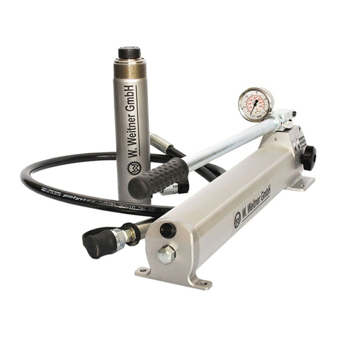
Werner Weitner WHE-1 User manual

Seite 1 von 7 WHE-1, WHE-2
Operating Instructions
hydraulic handpump
ww –WHE-1 + ww –WHE-2
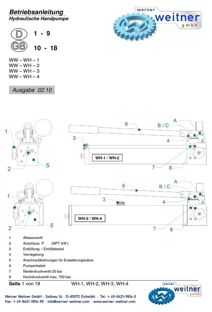
1 drain valve
2 Connection P (NPT 3/8”)
3 Venting- / filling cap
4 locking mechanism
5 Pump Lever
Read this operating manual and the safety instructions carefully before taking up the hand pump
WHE-1, WHE-2 into the operation!
1Basic operation and designated use of the machine
1.1 The machine has been built in accordance with state-of-the-art standards and the recognized safety rules. Nevertheless, its use may
constitute a risk to life and limb of the user or of third parties, or cause damage to the machine and to other material property.
1.2 The machine must only be used in technically perfect condition in accordance with its designated use and the instructions set out in
the operation manual, and only by safety-conscious persons who are fully aware of the risks involved in operating the machine. Any
functional disorders, especially those affecting the safety of the machine/plant, should therefore be rectified immediately!
1.3 The machine is exclusively designed for the use described in the operating manual. Using the machine for purposes other than those
mentioned in the manual, such as driving and controlling other pneumatic systems, is considered contrary to its designated use. The
manufacturer/supplier cannot be held liable for any damage resulting from such use. The risk of such misuse lies entirely with the user.
Operating the machine within the limits of its designated use also involves observing the instructions set out in the operating manual and
complying with the inspection and maintenance directives.
2 Organizational measures
2.1 The operating manual must always be at hand at the place of use of the machine!
2.2 In addition to the operating instructions, observe and instruct the user in all other generally applicable legal and other mandatory
regulations relevant to accident prevention and environmental protection.
This also applies for wearing protective clothing, helmet with visor or goggles and protective gloves.
2.3 In order to avoid injuries, the machine must only be operated by a specially trained operator who has undergone a safety training.
2.4 Observe all safety instructions and warnings attached to the machine. Make sure that safety instructions and warnings attached to
the machine are always complete and perfectly legible.
2.5 Never make any modifications, additions or conversions which might affect safety without the supplier's approval. This also applies to
the installation and adjustment of safety devices and valves.
2.6 Spare parts must comply with the technical requirements specified by the manufacturer. Spare parts from original equipment
manufacturers can be relied to do so.
Release 05.10

Seite 2 von 7 WHE-1, WHE-2
2.7 Replace hydraulic hoses at the specified or adequate intervals, even if no defects are detected which might affect safety. This must
be done after 10 years, at the latest!
2.8 Adhere to prescribed intervals or those specified in the operating manual for routine checks and inspections.
2.9 Make sure to dispose properly of packing material and dismounted parts!
3 General safety instructions
3.1 In the event of malfunctions, stop the machine immediately and lock it. Have any defects rectified immediately.
3.2 Before starting up or setting the machine in motion and during operation of the machine make sure that nobody is at risk.
3.3 Before transporting the machine always check that the accessories have been safely stowed away.
3.4 Make sure that there is enough lighting during work.
3.5 Avoid any operation that might be a risk to machine stability.
3.6 Check the machine at least after every operation for obvious damage and defects. Report any changes (incl. changes in the
machine’s working behaviour) to the competent organization /person immediately. If necessary, stop the machine immediately and lock it.
All lines, hoses and screwed connections have to be checked for leaks and obvious damage. Repair damage immediately. Splashed oil
may cause injury and fire.
3.7 All safety equipment has to be checked for completeness and flawless condition:
- instruction markings and warning signs (safety instructions)
- check safety cover (e.g. motor-safety covers, heat protection etc.) if they are available and if they are in good condition..
3.8 Working under loads is not allowed if they are only lifted by hydraulic cylinders. If the work is indispensable sufficient mechanical
supports are needed additionally.
3.9 Do not stress hoses mechanically (pulling, buckling etc.).
3.10 When working in the vicinity of live components and lines, suitable precautions must be taken against current conductions and high-
voltage flashovers on the hand pump and connected devices.
3.11 Prevent electrostatic charges with possible subsequent sparking from occurring when the unit is in operation.
3.12 When setting up the unit, ensure that the functionality and safety of the unit is not impaired by the influence of high external
temperature.
4 Instructions for maintenance and service
4.1 For the execution of maintenance and service work, tools and workshop equipment adapted to the task on hand are absolutely
indispensable.
Work on the hydraulic system must be carried out only by personnel having special knowledge and experience with hydraulic equipment.
4.2 Before putting into operation clean the machine, especially connections and threaded unions, of any traces of oil, fuel or
preservatives before carrying out maintenance/repair. Never use aggressive detergents. Use lint-free cleaning rags and pay attention that
the components are meticulously clean during reassembling after repair.
4.3 During dismantling of machines it is necessary to collect the outrunning hydraulic liquids completely, so that they cannot reach the
ground. They have to be disposed properly accord-ing to the instructions.
4.4 Always tighten any screwed and thread connections that have been loosened during maintenance and repair. Observe the stipulated
torques.
4.5 Aggressive material (acid, lye, solvent, vapour) can damage the machine. It is necessary to clean the whole machine if it must be
exceptionally operated under such conditions or gets into touch with these materials. Additionally, the machine must be checked as
described under 3.6.
5 Safety Instructions for Hydraulic hoses
All instructions as to safe use of hydraulic hoses can be found in the booklet deliverd with the hoses.
6 Intended use
6.1 General Instructions
The WHE-1 and WHE-2 hand pump is designed for operating single acting hydraulic cylinders and rescue devices. An operation of
cylinders other than is possible, but it must be approved by the manufacturer in each individual case.
Warning!
Please always observe the product restrictions regarding operating pressure, load limit values and
operating conditions. The operating pressure must not exceed the lowest max. operating pressure of
all system components.
NEVER set the pressure control valve to an operating pressure that is higher than the nominal pump
operating pressure specified in section 16. Higher settings may result in equipment damage and/or
personal injury.
Please ensure that the used volume of the hand pump (refer to section 16) is sufficient for operating
the connected cylinders and units.
The oil volume required for operation is specified in the technical data or the operating instructions of
the respective cylinders or units.

Seite 3 von 7 WHE-1, WHE-2
7 Function
7.1 Basis pump
All WHE-1 –WHE-2 series hand pumps have the one-stage design,. they are working with one speed:
a low speed in the high-pressure range (HP) for controlled extension of a cylinder with a load resting on it.
8 Putting into Operation
8.1 Preparing the pump
The pump is, normally, connected to a hydraulic cylinder by means of suitable pressure hoses
or, for Stationary applications via pipes. The hose connection nipple is to be mounted at
outlet „P“(2) on the pump head and to be tightened with a torque of 35 +5 Nm.
For using the pump you have to extract the locking (4) out of the drilling, which is positioned
in the pumphead, and turn it on 90° in a clockwise direction to unlock the pumplever (5).
The locking (4) has to snap in the drilling of the pumhead.To lock the pump, you have to think
gradually backward. At first you take the locking (4), extract it out of the drilling in the pumplever (5),
turn it on 90° contraclockwise and lock it in the drilling in the pumphead. The pumplever (5) acts as
a grasp for carrying.At first use of hanpump WHE-1, WHE-2 in high pressure zone, it is possible that a little
no-load stroke results. This no-load stroke adjusts itself after joining a cylinder, who was extended 2 - 3 times.
8.2 Venting the pump
Check the oil level (approx. 1-2 cm below upper edge of the oil container, depending
on the container size, ref. to section 16)
• Open drain valve (1)
• Actuate the pump several times.
8.3 Venting the cylinder
Connect the cylinder with the pump. Extend the piston by half its stroke and turn the cylinder so that the piston is facing downwards. The
highest point of the cylinder must be on a lower level than the pump. Fully extend the piston and retract again so that eventual air bubbles
can escape into the oil container of the pump.
Remark:
The oil filler cap of the pump must be open during bleeding. While retracting the piston air bubbles will be pushed via the hydraulic hose
into the oil reservoir and can escape through the filler cap.
9 Operation of two single-acting cylinders and rescue devices
9.1 Connection of a single-acting hydraulic cylinder
system 50 MPa system 70 MPa
9.1.1 Operation of a single-acting cylinder
- fully close the hand wheel (1) on the pump head (turn it clockwise)
- extend the cylinder by operating the hand lever of the pump. Observe safety remarks as per para 10.1!
9.1.2 Connecting a single acting rescue device
The unit is connected to the pressure hose line marked in red. If present, the return hose line marked in blue has no function.
9.2. Connection of rescue device
9.2.1 Actuating the rescue device
The pump is prepared for the subsequent work steps by turning the relief wheel at the relief valve to the right (closed = pressurized)
(Close relief valve of the pump by hand only. The use of tools, pincers in particular, may damage the valve seat) and by turning the
locking cap at the oil-filler neck (3) (in order to let the air out of the oil container).
The relief valve of the hand pump is normally kept closed. It must only be opened if the high-pressure hose cannot be coupled because
pressure has developed as a result of faulty operation or heat.
Hold the control valve of the rescue device in the desired direction of movement and actuate the pump lever.
Note: Carry out short strokes to save your strength when pumping under high pressure. The maximum pumping force is achieved during
the final five degrees of the stroke.

Seite 4 von 7 WHE-1, WHE-2
9.3 Connection of hose coupling to a cylinder
9.3.1 Quick couplers (system 50 Mpa) (not included in delivery, Special order)
Release mechanism until June 2003
Before coupling, remove the dust protection covers and unlock the connect socket with adjusting ring by turning it. Withdraw the sleeve
and connect plug and socket while holding the sleeve in this position. Release the sleeve and set the showglass to „red“ with the adjusting
ring. Now the parts are connected and locked. Decoupling is done in the reverse order.
Note regarding the modified release mechanism as of June 2003
When connecting the hoses, be aware of the following basic functions of the quick couplers:
In position X, retract sleeve –plug and socket are uncoupled - the device is coupled in reverse
order. The devices can only be coupled if the hose lines are depressurized.
The supplied dust caps are used to protect the couplers against dirt.
9.3.2 Screw couplers (system 70 Mpa)
- remove dust caps
- connect nipple SKN 2 on the hose with its female counterpart SKM 1 on the cylinder
- turn the threaded sleeve of SKM 1 by hand until it is tightened
10 Lifting a load, or building up pressure
10.1 Safety remarks as to safe use of the hand pump
Caution!
NEVER add extensions to pump handle. Extensions cause unstable pump operation.
Warning!
In certain situations the pump handle can "kick back".
Please ensure that your body does not face the pump frontally.
Note:
To reduce handle effort at high pressure, take short strokes. Maximum leverage is obtained in the last 5 degrees of stroke.
10.2 Observe „Safety measures prior to and during lifting“ as per separate operating manual of your cylinder
(also refer to the operating instructions of the cylinder or device being used).
11 Lowering a load (pressure release)
11.1 Open the oil filler cap (3) on the reservoir a few turns
11.1.1 To retract the piston of the cylinder, open the drain valve of the pump carefully (rotation to the left). Closing the drain valve
(rotation to the right) will interrupt the drain process. By means of fine adjustment of the drain valve, an extremely precise retraction of the
piston of the cylinder is facilitated
11.2 Special function „quick stop“ (must be ordered separately)
If you open the drain valve rapidly (rotation to the left), an existent quickstop only for 50 MPa cylinders StMu61-M (silver) is activated, i.e.
a non-return valve, incorporated in the quick-connect coupling, will prevent the oil from flowing back. While the hose is at zero pressure,
the cylinder remains under pressure. Pump and cylinder can now be separated and the pump can be used elsewhere.
The "quickstop" also serves as a safety valve if for some reason the hose is damaged. The quickstop will in this case prevent the load
from falling.
In order to release the quickstop, the pressure in the cylinder must be increased with a few pump slaps. This will re-open the non-return
valve in the quick-connect plug StNi 6. The draining can now be continued.
11.3 Uncoupling pump and cylinder or device
Before uncoupling the pump from the cylinder, make sure (by opening the drain valve) that there is no pressure and that the piston is
completely retracted or the device has come to rest according to the operating instructions.
Remount the protection caps after uncoupling in order to avoid pollution of the coupling parts. Close the oil reservoir filler cap, so that no
oil is spilled during transport.

Seite 5 von 7 WHE-1, WHE-2
12 Servicing and Maintenance
For safety reasons, the operating pressure must be checked after approx. one month. Despite accurate factory settings and testing, the
max. operating pressure that can be achieved can change after start-up of the device. If there are any deviations from the tolerance
(operating pressure) specified in section 16, either readjust the pressure valve according to section 4, or contact an authorised dealer or
the customer service.
The first oil change should be carried out after six months upon completion of a pressure check. If the contact pressure deviates from the
nominal pressure specified in the operating instructions, the pressure valve must be adjusted by an authorised dealer or the customer
service.
The oil must be changed once per year. In case of frequent use or operation in particularly dusty
environment, oil should be changed every six months. Further, it is mandatory to clean the oil sieve in the oil container of the pump each
time the oil is changed.
12.1 Adding Oil to the Pump
Warning: Always add oil with cylinders fully retracted (extended if pull cylinders) or the system will contain more oil than the
reservoir can hold.
- Remove vent/fill cap from reservoir,
- Only fill the oil to approx. 2.0-2.5 cm below the upper edge of the oil container (depending on the size of the container),
- Remove air from system if necessary. See 8.3. Recheck oil level after removing air,
- Return vent/fill cap to proper position.
- Make sure no dirt gets into the oil reservoir or into the pump, as this will cause malfunction.
- To extend pump life and improve performance, lubricate the beam pin A, cross pin Band piston head Cregulary, using roller bearing
grease. See cover page.
13 Transport
13.1 WHE-1, and WHE-2 hand pumps
For transport, the lever and the bolting device has to be a locking position. The lever can be used as a carrying handle.
14 Troubleshooting
If the defects cannot be repaired, contact an authorised dealer or the service department.
15 Warranty conditions
Please refer to the general terms and conditions of the manufacturer.
or Weitner themselvesor other cylinder damage
Have cylinder serviced by a authorised dealerCylinder retraction spring brockennormal
Use larger diameter hydraulic hoseHose I.D. too narrowslowly than
Remove air according to the instructions 8.3Air trapped in systemretracts more
Check that all couplers are fully tightenedLoose hydraulic couplerpart way, or
Drain oil level to full mark. See 12.1 instructions for adding oilPump reservoir is over-filledretract, retracts
Open drain valveDrain valve closedCylinder does not
Have pump serviced by a authorised dealer or Weitner themselvesInternal leakage in pumppressure
authorised dealer or Weitner themselvesdoes not hold
Locate leak(s) and have equipment serviced byLeaking sealsadvances, but
Check that all connections are tight and leak freeLeaking connectionCylinder
authorised dealer or Weitner themselves
Check for damage to cylinder; have cylinder by aCylinder plunger binding
Remove air according to the instructions on page 8.3Air trapped in systemspurts.
Do not attempt to lift more than rated tonnageLoad is too heavyor advances in
Check that all couplers are fully tightenedLoose hydraulic coupleradvances slowly,
Drain valve closedDrain valve openadvance,
Add oil according to the Maintenance instructions on 12.1Oil level in pump reservoir is lowCylinder does not
SolutionPossible CauseProblem

Seite 6 von 7 WHE-1, WHE-2
16 Technical data
Type
WHE-1
WHE-2
Order no.
WHE-1 / Operating pressure
WHE-2 / Operating pressure
Operating pressure (psi)
5800 - 10150
+ 58
5800 - 10150
+ 58
- 14,5
- 14,5
Oil capacity / usable oil capacity (l)
0,5 / 0,7
0,9 / 1,3
Oil delevery HP cm³
2,0 per piston stroke
2,0 per piston stroke
Dimensions LxBxH (mm)
340 x 100 x 150
550 x 100 x 150
Weight with oil (kg)
3,5
4,7
16.1 Oil recommendations
For hydraulic devices, use mineral oil in accordance with DIN 51 524 and others
Range of oil temperature
Viscosity rating
Remarks
A
- 24 ... + 30°C
HL 5
B
- 18 ... + 50°C
HLP 10
C
-8 ... + 75°C
HLP 22
D
+ 5 ... + 80°C
HLP 32
Recommended viscosity range: 10…200 mm²/s, delivered with HLP 10 to DIN 51 524.

Seite 7 von 7 WHE-1, WHE-2
WHE-1 WHE-2
Best. Nr. 101WHE sealing packung
Best. Nr. 102WHE standard packung consisting of: 1, 2, 3, 4, 5, 6, 7, 8, 9, 10, 11, 12, 13, 14, 15,
Best. Nr. 103WHE pump lever
Best. Nr. 104WHE drain valve
Best. Nr. 105WHE plumger incl. Sealing
Best. Nr. 106WHE HP-valve 400 - 700 bar
Best. Nr. 113WHE Tank complete 0,5 NV / 0,7 FV Best. Nr. 117WHE Tank standard
Best. Nr. 114WHE Tank complete 0,9 NV / 1,3 FV Best. Nr. 118WHE Tank standard
consisting of: 4, 5, 18, 19, 20, 22
consisting of: 2, 11, 16, 21, 23, 31
consisting of: 3, 5, 10, 24, 25
consisting of: 12, 13, 14, 15, 26, 27, 30, 32
16, 17, 18, 19, 20, 21, 28
handpump 400-700 bar
spare equipment / parts list
consisting of: 1, 2, 3, 4
This manual suits for next models
1
Table of contents
Other Werner Weitner Water Pump manuals
Popular Water Pump manuals by other brands
CTS
CTS MultiPump CTS2024 Instructions and precautions

WITA
WITA Delta HE 35 LCD Series TRANSLATION OF THE ORIGINAL INSTALLATION AND OPERATING INSTRUCTIONS

IWAKI PUMPS
IWAKI PUMPS HRP-54V/H-1 instruction manual
Pfeiffer Vacuum
Pfeiffer Vacuum HIPACE 2300 IT operating instructions

VADA
VADA VFB-HM80 installation manual
Grundfos
Grundfos CMBE instructions
