Werner R2 Series User manual

Appendix A Auto Coil 2™SRL’s
USER INSTRUCTIONS
Page 1
ENGLISH
Model Length Minimum
Arrest Distance
Arrest
Force
ANSI
Standard
Lifeline Rated
Capacity
R230018 18 ft 54” 900 lbs. Avg ANSI Z359.14-2012
Class B
1” x .07” Polyester webbing 310 lbs.
R230050 50 ft 54’ 900 lbs. Avg ANSI Z359.14-2012
Class B
1” x .07” Polyester webbing 310 lbs.
R210010 10 ft 24” 900 lbs. Avg ANSI Z359.14-2012
Class A
3/16” Steel wire rope 310 lbs.
R210020 20 ft 54” 900 lbs. Avg ANSI Z359.14-2012
Class B
3/16” Steel wire rope 310 lbs.
R210040 40 ft 54” 900 lbs. Avg ANSI Z359.14-2012
Class B
3/16” Steel wire rope 310 lbs.
R213030 30 ft 54” 900 lbs. Avg ANSI Z359.14-2012
Class B
3/16” Steel wire rope 310 lbs.
R213060 60 ft 54” 900 lbs. Avg ANSI Z359.14-2012
Class B
3/16” Steel wire rope 310 lbs.

Page 2
Fall Indicator
For R2 series models with a web
lifeline there is a stitch pattern
near the hook (see gure 1).
On all other R2 series models
the snaphook contains a red
impact indicator (see gure 2).If
the device has suffered impact
loading from a fall, the snap
hook’s red impact indicator will
be visible and products should
be removed from service.
Horizontal Systems
Applications where the SRL is used horizontally or with a horizontal
system, the SRL and horizontal system components must be
compatible. Both the horizontal and vertical distances are required
for clearance calculations. Horizontal systems must be designed and
installed under the supervision of a qualied person.
These units are suitable for use with horizontal lifelines.
gure 2
STITCHING
TORN
gure 1
ENGLISH
RED
LOAD
INDICATOR

Appendix A Auto Coil 2™SRL’s
USER INSTRUCTIONS
Page 3
ENGLISH
Securing Dual Leg Models
1. Connect body of retractable unit to the rear D-ring on the
harness using the carabiner supplied or other compatible
hardware.
2. To connect the carabiner to the harness, rotate the gate
clockwise and push to the center of the carabiner. When
positioned around a connection point, release the gate to
close and lock. See gure 3. The SRL should be attached to
the back D-ring.
gure 3
UNLOCKE
D
LOCKED TWIST

Page 4
ENGLISH

Appendix A Auto Coil 2™SRL’s
USER INSTRUCTIONS
Page 5
ENGLISH
© 2016 Werner Co.
P/N107027-03
Rev B 10/16
Read all warnings and instructions in
User Manual prior to use and follow
accordingly. If missing, contact Werner
Co. for a replacement. Inspect product
prior to each use, then at least monthly by a
competent person who is not a user. Before use
withdraw and retract some cable and tug sharply
to ensure that the pawls engage properly and the
unit retracts normally. Avoid exposure to sharp
edges, chemicals, or environmental hazards
that could weaken the product. User
repairs or alterations are NOT permitted.
Only the harness back D-ring (A) to
be used for fall arrest. Verify
If the red indicator on the snaphook
is visible, this indicates the product
has seen a fall and should be
removed from service.
See the User Manual for more
details. User must be trained
before using this product.
connectors are compatible (see User
Manual). Ensure that the anchorage
strength is 5,000 lbs. (22kN) or more,
or certified by a Qualified Person to take
twice the foreseeable load. To minimize
swing fall, anchor as directly above work
area as possible. Check for unobstructed
clearance beneath. Do not permit the lifeline to
become slack. Verify that this product is suitable
for the chosen fall protection. See instructions
for suitability for horizontal use and horizontal
lifeline compatibility.

Page 6
ENGLISH
SELF RETRACTING
LIFELINE
Read all warnings and instructions in User Manual prior to use
and follow accordingly. If missing, contact Werner Co. for a
replacement. Inspect product prior to each
use, then at least monthly by a competent
person who is not a user. Before use
withdraw and retract some cable and tug
sharply to ensure that the pawls engage
properly and the unit retracts normally.
Avoid exposure to sharp edges,
chemicals, or environmental hazards
that could weaken the product.
User repairs or alterations are
NOT permitted.
© 2016 Werner Co.
P/N107028-07 Rev B 10/16
Model: R210040
Lifeline Length: 40 feet
Material-Diameter/Width & Thickness:
Galvanized Steel Wire Rope
.1875" Diameter
Mk 2
Only the harness back D-ring (A) to be used for
fall arrest. Verify connectors are compatible (see
User Manual). Ensure that the anchorage
strength is 5,000 lbs. (22kN) or more, or certified by
a Qualified Person to take twice the foreseeable load.
To minimize swing fall, anchor as
directly above work area as possible. Check
for unobstructed clearance beneath. Do
not permit the lifeline to become slack.
Verify that this product is suitable for the
chosen fall protection. See instructions
for suitability for horizontal use and
horizontal lifeline compatibility. If the
red indicator on the snaphook is
visible, this indicates the product
has seen a fall and should be
removed from service. See the User
Manual for more details. User must be
trained before using this product.
WARNING
WARNING (continued)
Date
Initial
Inspection Log
Standard Code
Z359.14-2012 Class B
OSHA 1910 & 1926
FAILURE TO READ AND HEED
ALL WARNINGS COULD
RESULT IN INJURY
OR DEATH!
Arrest Distance: 54" or Less
Average Arrest Force: 900 lbs.
Serial Number: XXXXXX
Manufactured: MM/YYYY
Maximum User Weight: 310 lbs.
SELF RETRACTING
LIFELINE
Read all warnings and instructions in User Manual prior to use
and follow accordingly. If missing, contact Werner Co. for a
replacement. Inspect product prior to each
use, then at least monthly by a competent
person who is not a user. Before use
withdraw and retract some cable and tug
sharply to ensure that the pawls engage
properly and the unit retracts normally.
Avoid exposure to sharp edges,
chemicals, or environmental hazards
that could weaken the product.
User repairs or alterations are
NOT permitted.
© 2016 Werner Co.
P/N107028-08 Rev B 10/16
Model: R213060
Lifeline Length: 60 feet
Material-Diameter/Width & Thickness:
Galvanized Steel Wire Rope
.1875" Diameter
Mk 2
Only the harness back D-ring (A) to be used for
fall arrest. Verify connectors are compatible (see
User Manual). Ensure that the anchorage
strength is 5,000 lbs. (22kN) or more, or certified by
a Qualified Person to take twice the foreseeable load.
To minimize swing fall, anchor as
directly above work area as possible. Check
for unobstructed clearance beneath. Do
not permit the lifeline to become slack.
Verify that this product is suitable for the
chosen fall protection. See instructions
for suitablity for horizontal use and
horizontal lifeline compatibility. If the
red indicator on the snaphook is
visible, this indicates the product
has seen a fall and should be
removed from service. See the User
Manual for more details. User must be
trained before using this product.
WARNING
WARNING (continued)
Date
Initial
Inspection Log
Standard Code
Z359.14-2012 Class B
OSHA 1910 & 1926
FAILURE TO READ AND HEED
ALL WARNINGS COULD
RESULT IN INJURY
OR DEATH!
Arrest Distance: 54" or Less
Average Arrest Force: 900 lbs.
Serial Number: XXXXXX
Manufactured: MM/YYYY
Maximum User Weight: 310 lbs.

Appendix A Auto Coil 2™SRL’s
USER INSTRUCTIONS
Page 7
ENGLISH
SELF RETRACTING
LIFELINE
Arrest Distance: 54" or Less
Average Arrest Force: 900 lbs.
Read all warnings and instructions in User Manual prior to use
and follow accordingly. If missing, contact Werner Co. for a
replacement. Inspect product prior to each
use, then at least monthly by a competent
person who is not a user. Before use
withdraw and retract some cable and tug
sharply to ensure that the pawls engage
properly and the unit retracts normally.
Avoid exposure to sharp edges,
chemicals, or environmental hazards
that could weaken the product.
User repairs or alterations are
NOT permitted.
© 2016 Werner Co.
P/N107028-09 Rev B 10/16
Model: R230050
Lifeline Length: 50 feet
Serial Number: XXXXXX
Manufactured: MM/YYYY
Material-Diameter/Width & Thickness:
Polyester Webbing
1" Wide x .07" Thick
Mk 2
Only the harness back D-ring (A) to be used for
fall arrest. Verify connectors are compatible (see
User Manual). Ensure that the anchorage
strength is 5,000 lbs. (22kN) or more, or certified by
a Qualified Person to take twice the foreseeable load.
To minimize swing fall, anchor as
directly above work area as possible.
Check for unobstructed clearance beneath.
Do not permit the lifeline to become slack.
Verify that this product is suitable for the
chosen fall protection. See instructions
for suitability for horizontal use and
horizontal lifeline compatibility. If the
red indicator on the snaphook is
visible, this indicates the product
has seen a fall and should be
removed from service. See
the User Manual for more details.
User must be trained before using
this product.
WARNING
WARNING (continued)
Date
Initial
Inspection Log
Standard Code
Z359.14-2012 Class B
OSHA 1910 & 1926
FAILURE TO READ AND
HEED ALL WARNINGS
COULD RESULT IN
INJURY OR
DEATH!
Maximum User Weight: 310 lbs.

Page 8
ENGLISH
Arrest Distance: 24" or Less
Average Arrest Force: 900 lbs.
Standard Code
Z359.14-2012 Class A
OSHA 1910 & 1926
SELF RETRACTING LIFELINE
Model: R230007
Lifeline Length: 7 feet
Serial Number: XXXXXX
Manufactured: MM/YYYY
Material-Diameter/Width & Thickness:
Polyester Webbing 1" Wide x .07" Thick
Inspection Log
Date Initial
P/N107063-01
Rev A 10/14
Mk 2
Maximum User Weight: 310 lbs.
Arrest Distance: 24" or Less
Average Arrest Force: 900 lbs.
Standard Code
Z359.14-2012 Class A
OSHA 1910 & 1926
SELF RETRACTING LIFELINE
Model: R210010
Lifeline Length: 10 feet
Serial Number: XXXXXX
Manufactured: MM/YYYY
Material-Diameter/Width & Thickness:
Galvanized Steel Wire Rope .1875" Diameter
Inspection Log
Date Initial
P/N107063-06
Rev A 10/14
Mk 2
Maximum User Weight: 310 lbs.

Appendix A Auto Coil 2™SRL’s
USER INSTRUCTIONS
Page 9
ENGLISH
Read all warnings and instructions in User Manual
prior to use and follow accordingly. If missing, contact
Werner Co. for a replacement. Inspect product prior to each
use, then at least monthly by a competent person who is not a user.
Before use withdraw and retract some webbing and tug sharply to
ensure that the pawls engage properly and the unit retracts normally.
Avoid exposure to sharp edges, chemicals, or environmental hazards that
could weaken the product. User repairs or alterations are NOT permitted.
Only the harness back D-ring (A) to be used for fall arrest. Verify connectors are
compatible (see User Manual). Ensure that the anchorage strength is
5,000 lbs. (22kN) or more, or certified by a Qualified Person to take
twice the foreseeable load. To minimize swing fall, anchor as directly
above work area as possible. Check for unobstructed clearance beneath.
Do not permit the lifeline to become slack. Verify that this product is
suitable for the chosen fall protection. See instructions for suitability
for horizontral use and horizontal lifeline compatiablity.
If the stitching is torn, this indicates that the product has seen
a fall and should be removed from service.
See the User Manual for more details. User must be trained before
using this product.
© 2016 Werner Co.
P/N 107101-03
Rev B 10/16
Read all warnings and instructions in User Manual
prior to use and follow accordingly. If missing, contact
Werner Co. for a replacement. Inspect product prior to each
use, then at least monthly by a competent person who is not a user.
Before use withdraw and retract some cable and tug sharply to
ensure that the pawls engage properly and the unit retracts normally.
Avoid exposure to sharp edges, chemicals, or environmental hazards that
could weaken the product. User repairs or alterations are NOT permitted.
Only the harness back D-ring (A) to be used for fall arrest. Verify connectors are
compatible (see User Manual). Ensure that the anchorage strength is
5,000 lbs. (22kN) or more, or certified by a Qualified Person to take
twice the foreseeable load. To minimize swing fall, anchor as directly
above work area as possible. Check for unobstructed clearance beneath.
Do not permit the lifeline to become slack. Verify that this product is
suitable for the chosen fall protection. See instructions for suitability
for horizontral use and horizontal lifeline compatiablity.
If the red indicator on the snaphook is visible, this indicates that
the product has seen a fall and should be removed from service.
See the User Manual for more details. User must be trained before
using this product.
© 2016 Werner Co.
P/N 107101-04
Rev B 10/16

Page 10
ENGLISH
Modelo Longitud Distancia de
detención
mínima
Fuerza de
detención
Norma ANSI
cumplida
Cuerda salvavidas Capacidad
nominal
R230018 18 pies
(4.88 m)
54” (61 cm) 900 lbs.
(408 kg) Prom.
ANSI Z359.14-20012
Clase B
Correa tejida de poliéster de
1” x .07”
310 lbs.
(140 kg)
R230050 50 pies
(15.24)
54” (1.37 m) 900 lbs.
(408 kg) Prom.
ANSI Z359.14-20012
Clase B
Correa tejida de poliéster de
1” x .07”
310 lbs.
(140 kg)
R210010 10 pies
(3.05 m)
24” (61 cm) 900 lbs.
(408 kg) Prom.
ANSI Z359.14-20012
Clase A
Cable de acero de 3/16” 310 lbs.
(140 kg)
R210020 20 pies
(6.1 m)
54” (1.37 m) 900 lbs.
(408 kg) Prom.
ANSI Z359.14-20012
Clase B
Cable de acero de 3/16” 310 lbs.
(140 kg)
R210040 40 pies
(12.19 m)
54” (1.37 m) 900 lbs.
(408 kg) Prom.
ANSI Z359.14-20012
Clase B
Cable de acero de 3/16” 310 lbs.
(140 kg)
R213030 30 pies
(9.1 m)
54” (1.37 m) 900 lbs.
(408 kg) Prom.
ANSI Z359.14-20012
Clase B
Cable de acero de 3/16” 310 lbs.
(140 kg)
R213060 60 pies
(18.29 m)
54” (1.37 m) 900 lbs.
(408 kg) Prom.
ANSI Z359.14-20012
Clase B
Cable de acero de 3/16” 310 lbs.
(140 kg)

Anexo A - Cuerdas Salvavidas
Auto-Retráctiles Auto Coil 2™
INSTRUCCIONES PARA EL USUARIO
ESPAÑOL
Página 11
Indicador de caída
Para los modelos serie R2 con
cuerda salvavidas de correa tejida,
hay un patrón de costura cerca
del gancho (vea la gura 1). En
todos los demás modelos Serie
R2, el gancho de cierre resortado
contiene un indicador de impacto
rojo (vea la gura 2).Si el dispositivo
ha recibido carga de impacto por
una caída, el indicador de impacto
rojo del gancho de cierre resortado
será visible y los productos deben
sacarse del servicio.
Sistemas horizontales
Aplicaciones donde se utiliza el SRL horizontalmente o con un sistema
horizontal, el SRL y los componentes del sistema horizontal deben ser
compatibles. Las distancias horizontal y vertical, ambas son requeridas para
los cálculos de espacio libre. Sistemas horizontales deben ser diseñados e
instalados bajo la supervisión de una persona cualicada.
Estas unidades son adecuadas para uso con cuerdas de salvamento
horizontals.
gura 2
COSTURA
DESCOSIDA
/ ROTA
gura 1
INDICADOR
DE CARGA
ROJO

ESPAÑOL
Página 12
Sujeción de los modelos de dos (2) patas
1. Conecte el cuerpo de la unidad retráctil al anillo en “D” trasero del
arnés utilizando la argolla rectangular metálica suministrada u otros
herrajes compatibles.
2. Para conectar la argolla rectangular metálica al arnés, gire el cierre
en sentido horario y empuje hacia el centro de la argolla rectangular
metálica. Al colocar alrededor de un punto de conexión, libere el
cierre para cerrar y asegurar. Vea la Figura 3. La unidad de cuerda
salvavidas auto-retráctil debe conectarse al anillo en “D” de espalda.
gura 3
DESASEGURADOASEGURADO GIRE
105815-07 ©2016 Werner Co. Rev C 10/16
This manual suits for next models
7
Table of contents
Other Werner Security Sensor manuals
Popular Security Sensor manuals by other brands
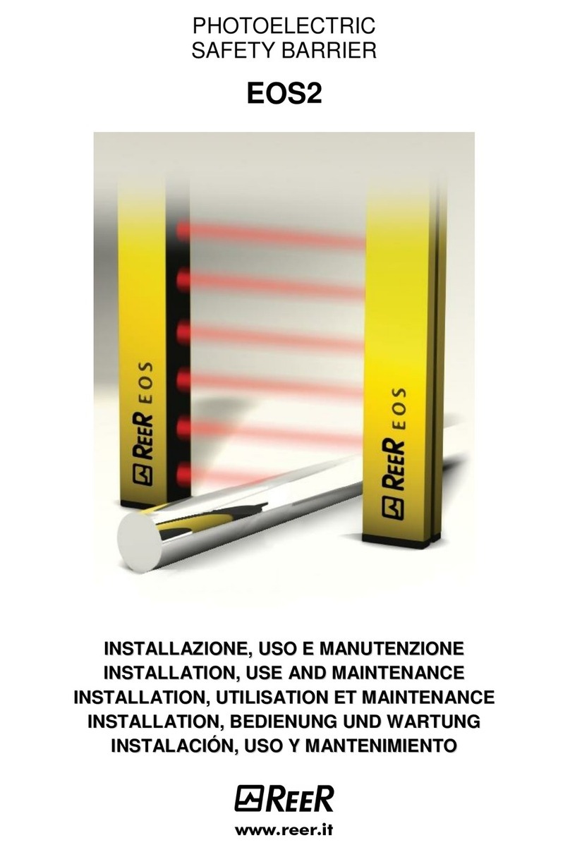
Reer
Reer EOS2 Installation, use and maintenance
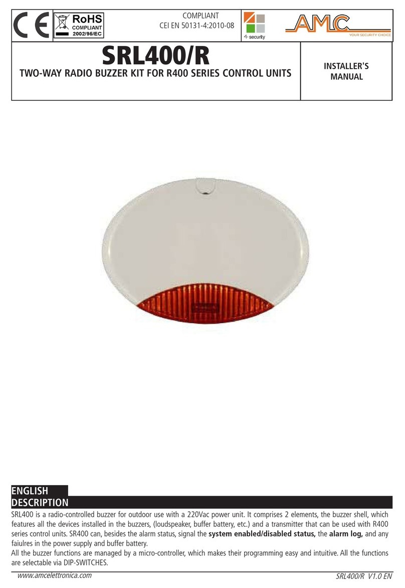
AMC
AMC SRL400/R Installer manual
Inficon
Inficon ELT3000 Translation of the original operating instructions
Bosch
Bosch DS935 VdS installation instructions

theben HTC
theben HTC thePrema P360-101 UP WH user guide
Elk Products
Elk Products ELK-319PIRW quick start guide
