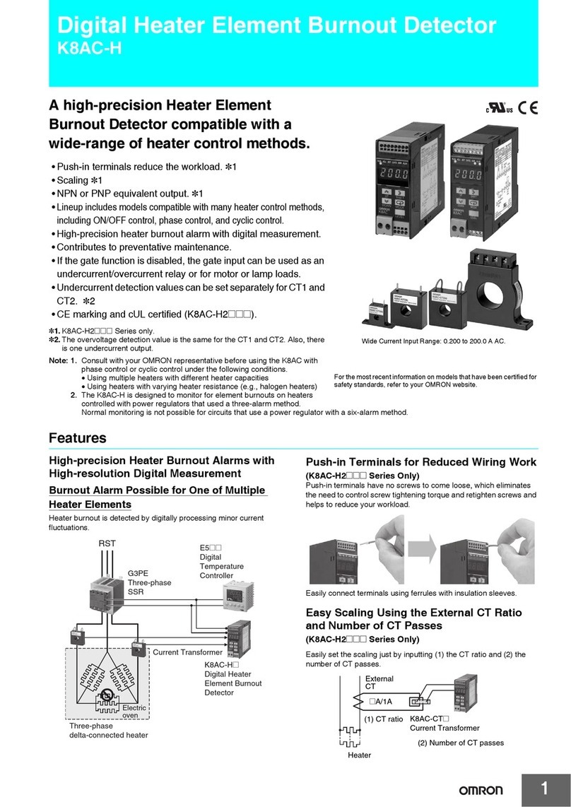
K8AC-H
9
Wiring Method When Using the K8AC-H with Cyclic Control Heaters
Wiring Method When Using the K8AC-H with Phase Control Heaters
Operation Description
•If the heater current detected at either CT1 or CT2
falls below the burnout alarm set value, an alarm is
output. The burnout alarm set value can be set
separately for CT1 and CT2.
No burnout alarm is output, however, when the
temperature controller control output is OFF.
Burnouts are detected only while the temperature
controller control output is being input to the gate input
terminals (11 and 12).
Burnout is detected with no errors because the
automatic adjustment of burnout alarm level is linked
to the temperature controller control output (4 to
20 mA).
•Burnout is detected when control outputs from the
temperature controller are 7 mA min.
Correct Usage
•Always take the control power supply from the primary
side of the SSR.
•Use a temperature controller with a 4 to 20-mA current
output.
•Always adjust the burnout alarm set value when the
temperature controller's control output is at 100%
(20 mA).
The value at 100% output is used as a reference for
adjusting burnout alarm levels to compensate for
inputs between 4 and 20 mA.
•CT1 and CT2 are special products. Use K8AC-CT@@.
•The CTs do not have polarity.
•Connect only one CT for single-phase heaters.
Connect two CTs for three-phase heaters.
•For three-phase heaters, always set the burnout alarm
set values for both CT1 and CT2.
Operation Description
•If the heater current detected at either CT1 or CT2
falls below the burnout alarm set value, an alarm is
output. The burnout alarm set value can be set
separately for CT1 and CT2.
No burnout alarm is output, however, when the
temperature controller control output is OFF.
Burnouts are detected only while the temperature
controller control output is being input to the gate input
terminals (11 and 12).
Burnout is detected with no errors because the
automatic adjustment of burnout alarm level is linked
to the temperature controller control output (4 to
20 mA).
•Burnout is detected when control outputs from the
temperature controller are 7 mA min.
Correct Usage
•Always take the control power supply from the primary
side of the Power Controller.
•Use a temperature controller with a 4 to 20-mA current
output.
•Always adjust the burnout alarm set value when the
temperature controller's control output is at 100% (20 mA).
The value at 100% output is used as a reference for
adjusting burnout alarm levels to compensate for inputs
between 4 and 20 mA.
•Adjust the burnout alarm set value at a 100% output for
gradient settings as well.
•If using the soft startup function with a power regulator, set
the soft startup function on the K8AC-H as well, to prevent
malfunctions.
•CT1 and CT2 are special products. Use K8AC-CT@@.
•The CTs do not have polarity.
•Connect only one CT for single-phase heaters.
Connect two CTs for three-phase heaters.
•For three-phase heaters, always set the burnout alarm set
values for both CT1 and CT2.
•When using the power regulator's gradient settings,
change the operation gate current level so that the heater
current value is within the measurement range. (The initial
value is 7 mA.)
For details on operating methods, refer to pages 18 to 19.
Heater
(See note.)
Power supply
SSR SSR
CT2
CT1
G32A-EA
Cyclic
Control Unit
Temperature
Controller
4 to 20 mA current output
3
78 910 11
12
13 1412
RS-485 communications
4
5
6
For transistor output
4
5
6
Note: Consult with your OMRON representative if multiple heaters
are connected in parallel different heater capacities, or if a
heater with varying heater resistance is used.
Heater
(See note.)
Power supply
Power
Regulator
CT2
CT1
Temperature
Controller
4 to 20 mA current output
3
78 910 1112
13 1412
RS-485 communications
4
5
6
For transistor outputs
4
5
6
Note: Consult with your OMRON representative if multiple heaters
are connected in parallel different heater capacities, or if a
heater with varying heater resistance is used.
