5
Po w e r T r a n s m i s s i o n
ROTOMEC USe and Maintenance handbook
0.4 MANUAL LAYOUT AND SYMBOLS
Part 0 - reference docUMentS
This handbook has been subdivided into topics in order to classify information and operators’ activity.
This handbook is composed of several PARTS (chapters) and sections dealing with operational topics to
enable correct installation, use and maintenance of the ROTOMEC hydromechanic couplings.
Pages have the following layout and contents:
This document is the property of WESTCAR srl. All copyrights reserved.
This handbook is an integral part to this partly completed machine and it has to be considered as a SAFETY
DEVICE; it provides both the purchaser and the personnel (operators and qualied technicians) with the
necessary installation, use and maintenance instructions in order to keep the product safe and in good working
order for its whole life-cycle.
We recommend to read and to fully understand the content of this manual.
Topics are dealt with in chapters and sections, so that each stage is clearly illustrated in a numbered step-
by-step sequence. At the beginning of each section a bar shows the symbols associated with the personnel
qualied for the task.
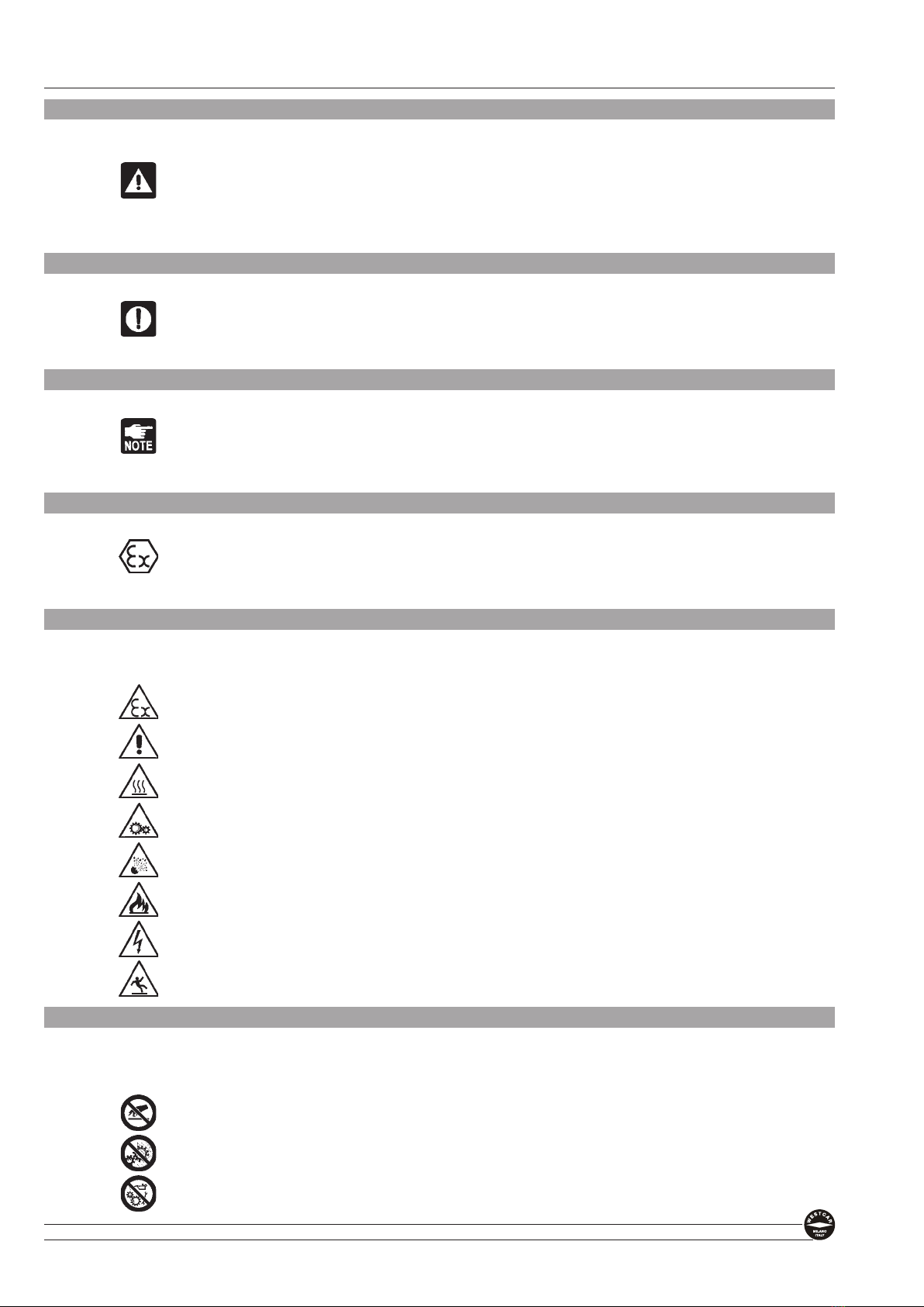
Any operation-related residual risk is highlighted through suitable symbols in the text. In the handbook some
symbols are used to highlight and differentiate particular instructions or recommendations, which are of crucial
importance for safe operation and/or correct use and maintenance.
These measures allow WESTCAR to draw operators’ and qualied technicians’ attention to the CAUTIONS,
WARNINGS OR NOTES concerning them.
For any further clarication on the content of this handbook, do not hesitate to contact your WESTCAR
Customer Support Service.
fax (+39) 02 76110041 web site: www.westcar.it
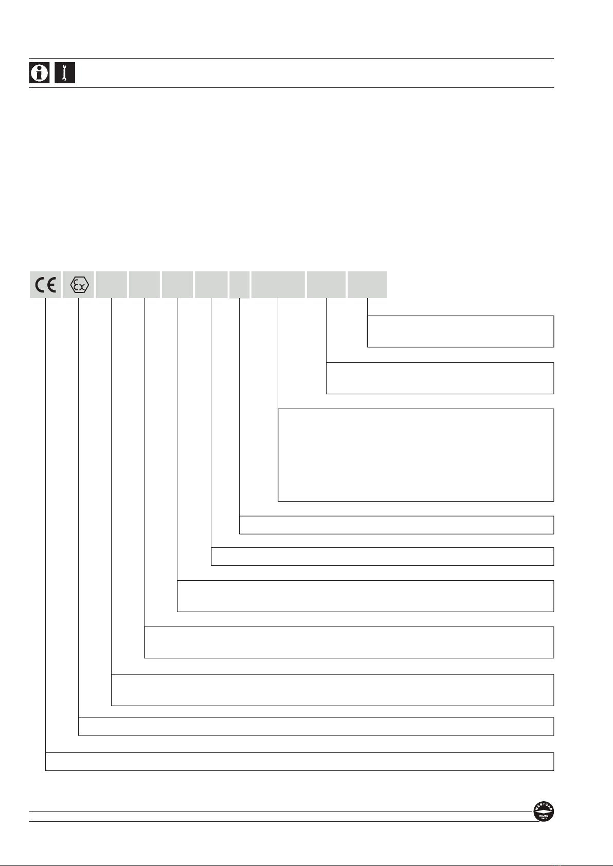
GRAPHIC DESIGN AND
OPERATION SEQUENCES
PRECAUTIONS,
WARNINGS OR
NOTES
for safety and
operation
SYMBOLS
-
hazard
- prohibition
- obligation
PAGE
NUMBERS
HEADING OF
CHAPTER
OR PART
AUTHORIZED
PERSONNEL
HEADING OF
SECTION OR
TOPIC
24
P
ow e r
T
ra n s m i s s i o n
3.1 TRANSPORT OF COUPLING WITH PACKAGE
The handling and transport operations are reserved to the handling
technicians equipped with suitable personal protective equipment
(protection gloves, safety shoes). DANGER OF CRUSHING, CRASHING
AND/OR INJECTION
3.1.1
Upon reception of the supply, check the weight reported on the label.
CAUTION
DANGER OF TILTING AND CRUSHING:
The load within the packaging could be unbalanced; therefore abide by
the procedures set out. Do not roll or damage the packaging. RISK OF
OVERTURNING.
3.1.2
Spread the forks of the fork-lift truck (with capacity suitable for the weight to be
trasported) as much as possible. Lift the coupling with its packaging slowly and
transport it (keeping it as much close to the soil as possible, about 30 cm) and
put it under a shelter in a dry place; then get the fork-lift out of the way.
3.1.3
Open the upper part and remove the packaging.
CAUTION
DANGER OF ENVIRONMENTAL POLLUTION:
Do not dump packaging material in the environment, but keep it for any future
re-use or shipping to the manufacturer or dispose of it properly as industrial waste.
3.1.4
Remove any stiffening rib, plastic lm for internal protection and brackets that x
the hydromechanic coupling to the pallet.
NOTE
Should the product be sent to the factory for repair works or maintenance,
the hydromechanic coupling will have to be shipped in a new package.
The shipping procedure shall be previously agreed upon with WESTCAR.
3.1.5
Take the Original Instruction Handbook and check that the product is not dam-
aged, no parts are missing and the content complies with the order.
NOTE
Non-compliance must be reported to Westcar and it’s distributor within
eight days from the receipt date.
3.1.6
To store the coupling, observe what set out in section 3.3. STORAGE OF THE
COUPLING.
The transport the of coupling with packaging has thus ended; now it is
possible to follow the steps described in the next section.
Part 3 - tranSPort and inStallationROTOMEC USe and Maintenance handbook
25
P
ow e r
T
ra n s m i s s i o n
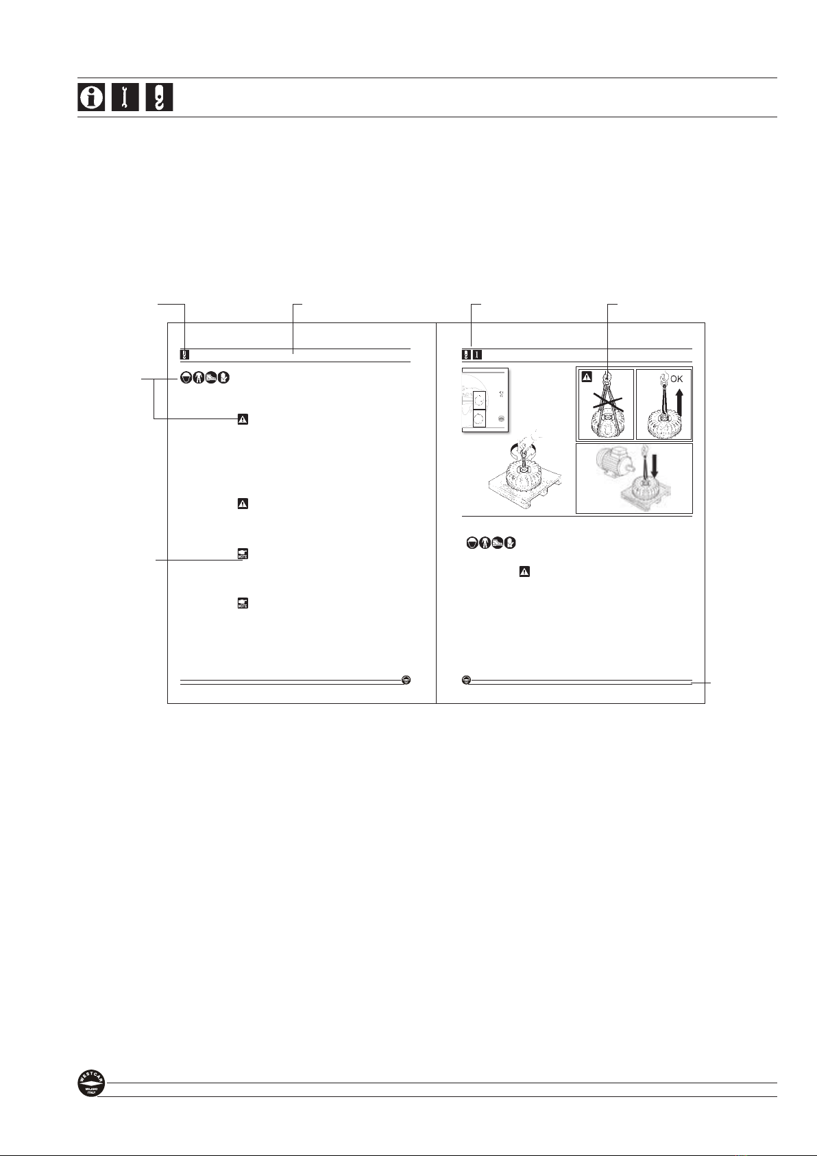
To handle the hydromechanic coupling without its package, it is necessary to follow
this procedure:
The handling and transport operations are reserved to handling technicians
equipped with suitable personal protective equipment (protection gloves,
safety shoes). DANGER OF CRUSHING.
3.2.1
Take the instructions and follow the description.
CAUTION
RISK OF CUSHING. In order to hoist and handle the hydromechanic
coupling, use the suitable lugs and devices recommended by the manufac-
turer, available on request; do not use any other reference than the equip-
ment and lifting points recommended by the manufacturer.
3.2.2 - For couplings with more than 30 kg of weight:
The hydromechanic coupling is located inside its packaging with its axis in verti-
cal position. Screw in the threaded pin equipped with hoisting ring in the extrac-
tion hole of the coupling.
3.2.3
Sling the coupling through the hoisting ring with hoist lines of suitable load
capacity for the coupling weight (see Identication Plate).
3.2.4
By slow movements, lift the coupling and transfer it to a dry, sheltered place and lay it
on a wooden plane next to motor and drive end, where the coupling will be installed.
The transport of the coupling without packaging has thus ended; now it is
possible to follow the procedure as set out in the next section.
3.2 HANDLING OF THE COUPLING WITHOUT PACKAGE
3.2.2
3.2.3
3.2.4
3.2.1
Part 2 - WarningS and PreScriPtionS ROTOMEC USe and Maintenance handbook
Original Instructions
WESTCAR s.r.l.
ViaMonte Rosa 14
20149- MILANO
Tel.+39-02-76110319
Fax+39-02-76110041
www.westcar.it
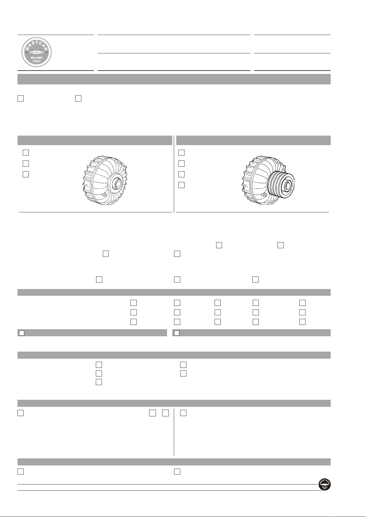
Constant-fill
HYDRO
MECHANIC
COUPLINGS
ROTOMEC
®
ROTOMECALFA
ROTOMECBETA
M2021-ENG- ed. 2021-02