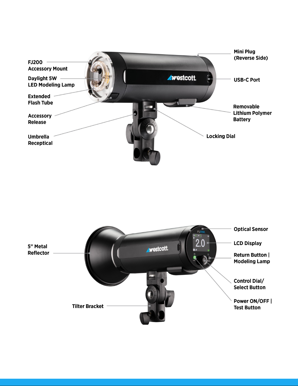
FJ200 Strobe: Firmware Updates
The FJ200 strobe is designed with a USB-C port to allow for firmware updates only (no charging). Future
firmware updates could result in performance enhancements, modified menu options and menu layouts.
It is strongly suggested that you visit westcott.com/4740 to confirm your strobe has the latest firmware.
Installing the Firmware
1. Visit westcott.com/4740 and scroll to the Support section. Find and download the latest
firmware ZIP file.
a. NOTE: Various browsers may automatically unzip the ZIP file. In this scenario, skip to Step
#3.
2. Unzip the file and open the extracted folder.
3. IMPORTANT: Read ALL FILES located in the extracted folder (i.e. README, Changelog, etc).
4. Ensure the F200 is OFF and cooled before removing the battery from the strobe.
5. Connect the USB-A to USB-C cable to the FJ200’s USB-C port.
6. Common operating systems will present the strobe as an external drive device.
a. NOTE: MacOS may display the external device on the desktop or in the Finder window.
7. Locate the .BIN file on your computer and drag the file to the F200 (external device).
a. NOTE: The file ending in .BIN will be the ONLY file copied to the FJ200.
8. Once the file has been completely copied to the FJ200, EJECT the FJ200 from the computer.
9. Remove the USB-C cable from the FJ200 and reinsert the battery.
10. Long press the Power | Test button on the FJ200 to initiate the firmware update and confirm
installation was successful by locating the firmware text in the bottom right corner of the screen
during the start-up process.
IMPORTANT
●If FJ devices don’t display as an external device after being connected to the computer, then
please disconnect the USB cable from both devices, restart the computer, and restart the
firmware installation process.
●It’s recommended that the firmware update installation process be completed only when the
connected computer’s power level is ≥ 50%. Loss of power of any type during this process could
render the FJ200 inoperable and require professional repair.
●Removing the USB-C cable from the FJ200 without properly ejecting the FJ200 from your
computer could render the strobe inoperable and require professional repair.
●Depending on the operating system and the applications running, copying the firmware from your
computer to the FJ200 may take a few minutes and/or halt the copying process. Should this
happen, close the copy progress window and try again. Further copying issues may require the
computer to be restarted.