Westell 28MA202 Series User manual

Equipment Issue C
030‐101670 Rev. C, May 2012
Section 28M‐A20‐200‐20C
1205ICRC
Copyright 2012 Westell, Inc. All rights reserved.
200 MECHANICSand Westellare registered trademarks of Westell, Inc. Page 1 of 8
28MA202 Series of Universal Mounting Assemblies
CONTENTS PAGE #
1. GENERAL 1....................................
2. APPLICATIONS 2...............................
3. OPTIONS & FEATURES 2.......................
4. INSTALLATION 4...............................
5. TESTING & TROUBLESHOOTING 7..............
6. CUSTOMER & TECHNICAL SERVICES 7.........
7. WARRANTY & REPAIRS 7.......................
8. SPECIFICATIONS 8.............................
9. ACRONYMS & ABBREVIATIONS 8...............
1. GENERAL
1.1 Document Purpose
This document describes the Westell 28MA202 Series of Uni
versal Mounting Assemblies. Models covered in this document
are listed in Table 1, and a typical model is shown in Figure 1.
‐ NOTE ‐
Hereafter, all models may be commonly referred to as the
“28MA202” or “the mounting.” Specific model numbers will be
used where differences apply.
1.2 Document Status
Whenever this practice is updated, the reason will be stated in
this Paragraph. This practice replaces practice 030‐101427 for
the models shown in Table 1. This practice reflects the Issue C
equipment, which provides a #6 ground lug instead of the pre
vious ground screw terminal. Revision B updates Table 1, and
Paragraphs 3.3 and 3.4.2. Revision C updates Figure 4 and
Paragraphs 3.1 and 3.3.2.
1.3 Product Purpose and Description
The 28MA202 is a compact mounting that houses one 400‐type
plug‐in module or up to two half‐width (200 MECHAN
ICS‐type) plug‐in modules. These plug‐in modules may be any
of the following types of units.
T1 Network Interface Units (NIUs)
Digital Data System Network Interface Units (DDS‐NIUs)
HDSL Remote units
Any UL‐recognized NEBS‐compliant plug‐in units that
meet the wiring plan of the 28MA202
Figure 1. Isometric Front View of 28MA202
‐ NOTE ‐
To maintain the UL Listing of these mountings, only UL recog
nized modules are to be used.
The universal mounting offers switchable RJ48C/RJ48S cus
tomer jacks, and offers security features to help prevent
unauthorized access to the plug‐in modules and the Facili
ty/Telco wiring area. Modules installed in the mounting can be
either span or locally powered (28MA202 models that are
equipped with a power supply for local power applications con
tain a “P” in the model number [see Table 1]).
1.4 Product Mounting
The 28MA202 is typically mounted to a wall or on an equipment
backboard at the customer premises.
1.5 Product Features
The 28MA202 offers the following features.
Slim‐designed, compact, wall mount enclosure
Metal construction
Secure cover for Facility‐side wiring connections (also con
tains lead seal)

Section 28M‐A20‐200‐20C 030‐101670 Rev. C
1205ICRC
2
Part Number
CLEItCode CPR / Barcode
Facility‐Side
Connections
CPE Connections
Power Supply
(Included)
Key‐Lock
Cover
Screw Terminals RJ48C Jacks RJ48S Jacks
C90‐28MA202 NCM4RD9DRB N70596 / 440457
C90‐28MA202K NCM46D9DRA N70734 / 441209
C90‐28MA202P NCM5FGECRB N70596 / 440458
Options and Additional Equipment, Ordered Separately
Part Number Description
DTMWB4 QuikKit wall-mounting plate: holds up to four mounting assemblies. Consult practice 030-300552.
CLEI Code: VAMYABTRAA. CPR: 099999. Barcode: 441768.
DTMWB7 QuikKit wall-mounting plate: holds up to seven mounting assemblies. Consult practice 030-300552.
CLEI Code: VAMYABURAA. CPR: 099999. Barcode: 441769.
A90‐204100 Power supply: 1.25 A at ‐48 VDC output; 117 VAC input. Equipped with P versions, or can be ordered separately.
CLEI Code: DSPUFVHCAA. Barcode: 285958.
Note: Within a part number; K = Key‐lockable. P = Power Supply included. CLEI is a trademark of Telcordia Technologies. (Unless otherwise indicated, all assemblies provide a lead‐seal
locking mechanism.)
Table 1. Ordering and Option Information
Secure front cover for module‐compartment (with see‐
through window)
Optional key‐lock for module compartment
Terminal block for external power source
#6 grounding lug
Choice of wirewrap or screw‐type Facility connectors
Switchable RJ48C/S modular jacks for customer connec
tions
Fully‐populated card‐edge connector helps hold modules
securely in the mounting position
Built‐in mounting brackets (one‐piece backplate)
Strain relief wiring grommet at cable entrance hole
Strategically‐located cable tie‐downs (ties included)
Circuit ID card and clear, plastic card packet
NEBS Level 3 compliant and UL1950 certified by an NRTL
1.6 Applications
The 28MA202 is a universal mounting that can be used in a vari
ety of applications, depending upon the type of module installed
in the mounting. The 28MA202 can house either HiCap or
DDS‐NIU plug‐in modules, as each 28MA202 is equipped with
two switches, one for each module slot, to set or change the de
sired module application or operating mode. See Part 2 for more
details.
2. OPTIONS & FEATURES
2.1 Exterior Features
The 28MA202 contains features and options accessible or vis
ible from the exterior of the mounting, as described in the
paragraphs below.
2.1.1 Facility/Power Wiring Cover
A protective and secure metallic cover for the Facility connec
tors and the power and ground connectors is provided at the top
of the 28MA202. The cover may be removed by loosening the
cover screw with a phillips‐head screwdriver. A cut‐out is pro
vided at the top of the cover for wiring/cable access through a
cable/wiring strain‐relief grommet.
2.1.2 Module Front Cover
The 28MA202 provides a removable protective cover for the
modules. The cover is metallic, except for the window through
which the installer may easily view the modules' status LEDs, for
testing purposes. A screw or an optional keyed lock secures and
limits access to the modules installed in the 28MA202 (see
Table 1 for specific features).
2.1.3 RJ48C/S Jacks
At the bottom of the 28MA202 under the module compartment
are two RJ48C/S jacks for customer connections. The jack on the
left side is labelled “A”, and corresponds with Circuit A or the left
module slot of the 28MA202. The jack on the right side is la
belled “B”, and corresponds with Circuit B or the right module
slot of the 28MA202. When a single 400‐type module is installed
in the mounting, use Jack A. Use the operating mode switch(es)
to set or option the jack type, RJ48C or RJ48S (also see Para
graph 2.1.4 and Figure 6).
2.1.4 Application/Operating Mode Switch
Two, identical, 2‐position slide switches, one for each module
slot in the 28MA202, are located on the right‐hand side of the

Section 28M‐A20‐200‐20C
030‐101670 Rev. C
1205ICRC 3
Figure 2. Exterior Mounting Features
Keyhole Mounting Slots
Facility/Power Wiring Cover
See‐Through
Screw Lock
Customer
Keyhole
Operating
Mode Switch
Mounting
Module
RJ 48C/S
Jacks
Circuit
Card
Sleeve
Convection Holes
(Top of Module Compartment)
Built‐in
Mounting
Bracket
Built‐in
Mounting
Bracket
(Removable)
Front
Cover
(Removable. See Figure 3.)
Slot
Cable Strain‐Relief Grommet
S
C
B
See Figure 4
for
key‐lockable
version.
mounting. The top switch is labelled switch “A”, and controls the
operating mode of Circuit A. Circuit A corresponds with the left
module slot in the 28MA202. Similarly, the bottom switch is la
belled “B” and controls Circuit B, which corresponds with the
right module slot. Each switch has two positions: S and C. The
S position denotes RJ48S, and is used with DDS‐NIU applica
tions. The C position denotes RJ48C, and is used with HiCap
applications. These switches must be set to the desired operating
mode prior to module insertion. If a single 400‐type module is
installed in the mounting, use the top switch, Switch A.
2.1.5 Circuit ID Card and Card Sleeve
A circuit identification card and a clear plastic card packet is pro
vided for customer convenience, to help the installer identify the
cards that are installed in the 28MA202.
2.1.6 Built‐in Mounting Brackets
A metal backplate at the rear of the 28MA202 contains built‐in
mounting brackets and three, pre‐drilled, key‐slotted mounting
holes. One mounting hole is at the top and two are at the bottom.
2.2 Interior Features
The 28MA202 contains various features on the interior of the
mounting. Some of these features are shown in Figure 3 and ex
plained in the paragraphs that follow.
TB2
TB1
FRAME
GND
+PWR
−PWR
GND
AB
T
R
T1
R1 P2
P1
T
R
T1
R1
RCV IN ‐
XMT OUT ‐
Screw‐type lock
TB2
Power/Ground
Terminal Strip
Frame Ground
Lug
(Keylock available
on some models
(See Figure 2 and
also see Table 1
for specific model
features.)
(For Wire Access)
Wiring Grommet
Cable Tie‐Down
Customer
RJ48C/S Jack
Figure 3. Interior Features of Facility/Power Compartment
(Facility Cover Removed)
TB1
Cable Tie‐Down
See Table 1 for specific
features for each model.
Connector
Screw‐
(Wire is inserted
into slot under
screw at the side
of the block connector,
then screw at top
is tightened.)
From Facility
To Facility
Type
2.2.1 Plug‐in Module Mounting Slots
The 28MA202 can accommodate up to two 200 MECHANICS
type modules (or one 400‐type module) and thus provides two
mounting slots, complete with card guides and two, 56‐pin, card‐
edge connectors. The slot on the left side of the 28MA202 corre
sponds with Circuit A, Switch A (Paragraph 2.1.4), and Jack A
(Paragraph 2.1.3). The right‐side slot corresponds with Circuit
B, Switch B, and Jack B. Ventilation/air convection holes at the
top and bottom of the 28MA202 allow heat produced by the
modules to escape or dissipate.
2.2.2 Facility Connectors
Two screw‐type terminal connectors, labelled “A” and “B” are lo
cated under the protective metallic Facility wiring cover
(Paragraph 2.1.1) at the top of the mounting. Connector A is
used with Circuit A (left module slot of the mounting). Connec

Section 28M‐A20‐200‐20C 030‐101670 Rev. C
1205ICRC
4
tor B is used with Circuit B (right module slot). (If a 400‐type
card is used in the mounting, use Circuit/connector A.) The four
screws of each connector are labelled “T”, “R”, “T1”, and “R1”.
Stripped facility wires are inserted into slots provided in the con
nector under each screw and held in place while each screw is
tightened to secure contact with the wire inserted below it (see
Figure 3). A narrow slotted or blade screwdriver is required.
2.2.3 Power/Ground Screw Terminal Block
TB2 is a 3‐position screw terminal block located under the Facil
ity wiring cover for power and ground connections. The top
position is labelled “+PWR” and is for connection to the +V
terminal of the power supply. The middle position is labelled
“GND” and is for connection to earth ground. The bottom posi
tion is labelled “‐PWR” and is for connection to the ‐V terminal
of the power supply. See Figure 5 and Figure 6 for more wiring
details for this TB2 terminal block.
2.2.4 Frame/Chassis Ground Lug
A frame ground lug labelled “TB1” is located under the Facility
wiring cover for a frame (chassis) ground connection. See
Figure 5 and Figure 6 for more details for this ground lug.
3. INSTALLATION
Installation consists of inspecting the equipment for damages,
following proper safety precautions, gathering the required
tools and equipment, determining the mounting location,
mounting the 28MA202, and making the appropriate ground
ing, power, and wiring connections. The following paragraphs
provide detailed instructions for performing these procedures.
‐ INSPECTION NOTE ‐
Visually inspect the unit for damages prior to installation. If the
equipment has been damaged in transit, immediately report the
extent of the damage to the transportation company and to West
ell (see Part 6 for telephone number).
3.1 Following Safety Precautions
‐ PRECAUTIONARY STATEMENT ‐
Never install telephone wiring during a lightning storm.
Never install telephone jacks in wet locations unless the jack
is specifically designed for wet locations.
Never touch uninsulated telephone wires or terminals unless
the telephone line has been disconnected at the network
interface.
Use caution when installing or modifying telephone lines.
This equipment is intended to be used behind devices that
provide primary lightning protection.
CAUTION
Risk of electric shock. Voltages up to 140 VDC (with reference to
ground) may be present on telecommunications circuits.
È
È
È
È
È
È
È
È
È
È
ÈÈÈÈÈÈÈÈ
ÈÈÈÈÈÈÈÈ
ÈÈÈÈÈÈÈÈ
Figure 4. Wall‐Mounting Diagram
Use 28MA202 backplate
as a template to mark
mounting hole locations
prior to drilling holes.
Be sure to use mounting
screws with a head
diameter less than the
diameter of the keyhole
mounting slots.
Equipment backboard or wall
Keylock Version
Model 28MA202K
Important Safety Instructions (Please Save)
When using your telephone/telecommunications equipment, al
ways follow basic safety instructions to reduce risk of fire,
electric shock, and injury to person, including the following:
A. Read and understand all instructions.
B. Follow all warnings and instructions marked on product.
C. Do not place this product on an unstable cart, stand or table: the
product may fall, causing serious damage to product.
D. Slots and openings in the cabinet and the back or bottom are pro
vided for ventilation. To protect it from overheating, these
openings must not be blocked or covered. This product should nev
er be placed near or over a radiator or heat register. This product
should not be placed in a built‐in installation unless proper ventila
tion is provided.
E. This product should be operated only from the type of power
source indicated on the marking label.
F. Never push objects of any kind into this product through cabinet
slots as they may touch dangerous voltage points or short out parts
that could result in the risk of fire or electrical shock. Never spill liq
uid of any kind on the product.
3.2 Gathering Tools and Supplies
The following tools and supplies are recommended to mount the
28MA202.
Screwdrivers (flat‐head and Phillips‐head)
Wood screws, or other appropriate wall fasteners
Utility knife
Awl or drill with assorted bits
Hammer
Pliers or line cutters
3.3 Determining the Mounting Location & Type
The 28MA202 should be installed by authorized trained person
nel only. This assembly is for installation of NEBS‐certified 200
MECHANICSor 400‐type cards. It is also recommended that

Section 28M‐A20‐200‐20C
030‐101670 Rev. C
1205ICRC 5
−
+
−PWR
+PWR
GND
TB2
A90-204100
PWR XFMR
48VDC 1.25A
GND
TB1
TB2
FRAME
GND
TB1
SPAN POWER
To ground window
(e.g., cold water pipe)
LOCAL POWER
**
CONNECTION TO BE PROVIDED AT TIME OF INSTALLATION
*
−PWR
+PWR
GND
−PWR
+PWR
GND
TB2
A90-204100
PWR XFMR
48VDC 1.25A
TB1
TB2
TB1
SPAN POWER
To ground window
(e.g., cold water pipe)
LOCAL POWER
*
*
−
+
GND
−PWR
+PWR
GND
To lightning
return ground To lightning return
ground
*
FRAME
GND
FRAME
GND
FRAME
GND
Figure 5. Typical Grounding Diagrams
The above method is preferred for compliance with Telcordia GR-1089.
Figure 5a. Preferred Grounding Diagram ‐ For Installations Where Separate Frame and Circuit Grounds are Provided
CONNECTION TO BE PROVIDED AT TIME OF INSTALLATION
*
The above method is preferred for compliance with Telcordia GR-1089.
Figure 5b. Alternate Grounding Diagram ‐ For Installations Where only a Single Ground Connection is Provided
* OPTIONAL GREEN WIRE STRAP PROVIDED WITH ASSEMBLY. * OPTIONAL GREEN WIRE STRAP PROVIDED WITH ASSEMBLY.
adequate horizontal and vertical space be left between multiple
installations to allow for proper cable access and ventilation.
The distance from the cable entry point should be consistent
with local installation practices.
‐ NOTE ‐
The 28MA202 described in this practice is typically wall‐
mounted. Several 28MA202's may be simultaneously installed
with wall‐mount kits. See Table 1 for kit information.
3.3.1 Mounting Several Assemblies Using Kits
Several 28MA202's can be simultaneously mounted using the
Westell QuikKit mounting plate. The DTMWB4 kit can hold up
to four 28MA202's while the DTMWB7 kit can hold up to seven
28MA202's. For additional information regarding the Westell
QuikKit, refer to Table 1 or order practice number 030‐200209.
3.3.2 Wall‐Mounting Single Assemblies (Typical)
Mount the 28MA202 per local company practice, or if none ex
ist, per the instructions below. The 28MA202 is typically
wall‐mounted at the customer premises. Westell recommends
mounting this 28MA202 to an equipment backboard or concrete
surface. The 28MA202 has a backplate with built‐in mounting
brackets that contain predrilled mounting holes (key‐slotted
holes).
1. Lift and place the 28MA202 on the wall in the desired
mounting location.
2. Mark the mounting screw‐hole locations.
3. Set aside the 28MA202. Drill appropriately‐sized pilot
holes (to accommodate the mounting screws being used) at
the marked locations before the next step. Hardware for
mounting the 28MA202 to the wall is not included.
4. Partially install all screws, leaving approximately ¼‐inch
protruding for hanging the mounting from the keyhole slots
provided.
5. Lift the 28MA202 again, align the mounting holes on the
28MA202 backplate with the partially‐installed screws, and
hang the 28MA202 on the protruding screws.
6. Tighten all screws in place.
7. To access the plug‐in module slots or wiring connectors, re
move the front covers.
3.4 Installer Connections
After mounting the 28MA202, installer connections may be per
formed. For wiring details, refer to Figure 5 and Figure 6.
Figure 3 is a front view showing the connector locations and
types.
‐ GROUNDING NOTE ‐
Always follow the National Electrical Code (NEC) rules, local safety pre
cautions, and standard operating procedures for grounding the equipment
when installing, upgrading, repairing or maintaining equipment. Any in
structions or information contained herein is subordinate to local codes,
operating procedures or practices.
3.4.1 Chassis/Frame Ground Connections
To ensure safety to personnel, Westell recommends grounding
the 28MA202 as shown in Figure 5a, unless local codes dictate
otherwise. For applications requiring chassis/frame ground to
be connected to circuit ground, as shown in Figure 5b, an option
al green wire strap is provided for installation between the TB2
GND terminal and the TB1 FRAME GND lug.

Section 28M‐A20‐200‐20C 030‐101670 Rev. C
1205ICRC
6
49
55
47
41
13
7
15
5
TO
CUSTOMER
EQUIPMENT
XMT
OUT
RCV
IN
TO
TELCO
FAC.
5-CT
4-CR
2-CT1
1-CR1
XMT
IN
RCV
OUT
T
R
T1
R1
TYPICAL OF
CIRCUIT A
Figure 6. Wiring Diagram
SCREW TERMINALS
XMT
IN
RCV
OUT
DDS/DST
HDSL/NIU
2−DTT
1−DTR
7−DRT
8−DRR
RJ48C
RJ48S
49
55
47
41
13
7
15
5
TO
CUSTOMER
EQUIPMENT
XMT
OUT
RCV
IN
TO
TELCO
FAC.
5-CT
4-CR
2-CT1
1-CR1
XMT
IN
RCV
OUT
T
R
T1
R1
SCREW TERMINALS
XMT
IN
RCV
OUT
DDS/DST
HDSL/NIU
2−DTT
1−DTR
7−DRT
8−DRR
RJ48C
RJ48S
SWITCH LOCATION
SWITCH LOCATION
*SEE
NOTE
*SEE
NOTE
*Note: the top switch is for the left card slot.
The bottom switch is for the right card slot.
35
27
17
−PWR
+PWR
GND
TB2
TB1
FRAME
GND
TYPICAL OF
CIRCUIT B
35
17
See Figure 5 For
Power Wiring
Connections
2
11
27
2
11
‐ NOTE ‐
When connecting the external power source to the mounting, a
readily‐accessible quick‐disconnect device must be incorporated
to ensure compliance of UL 1950.
3.4.2 Power Connections
Modules installed in the 28MA202 can be either span or locally
powered by an NRTL‐Listed Limited Power Source.
3.4.2.1 Span Power
Power connections are not necessary for use with span‐powered
modules; however, circuit ground on TB2 must be connected as
shown in Figure 5a.
3.4.2.2 Local Power ‐ P Versions Only
The A90‐204100 power supply, equipped with the “P” models,
terminates at the mounting via the TB2 3‐position screw termi
nal block located in the top Network compartment of the
mounting. The terminal block will accept stranded or solid wire.

Section 28M‐A20‐200‐20C
030‐101670 Rev. C
1205ICRC 7
Consult the power supply practice for more details on the power
supply. Dress wires per company practice and secure wires with
cables ties to the tie‐down provided on the mounting (after test
ing).
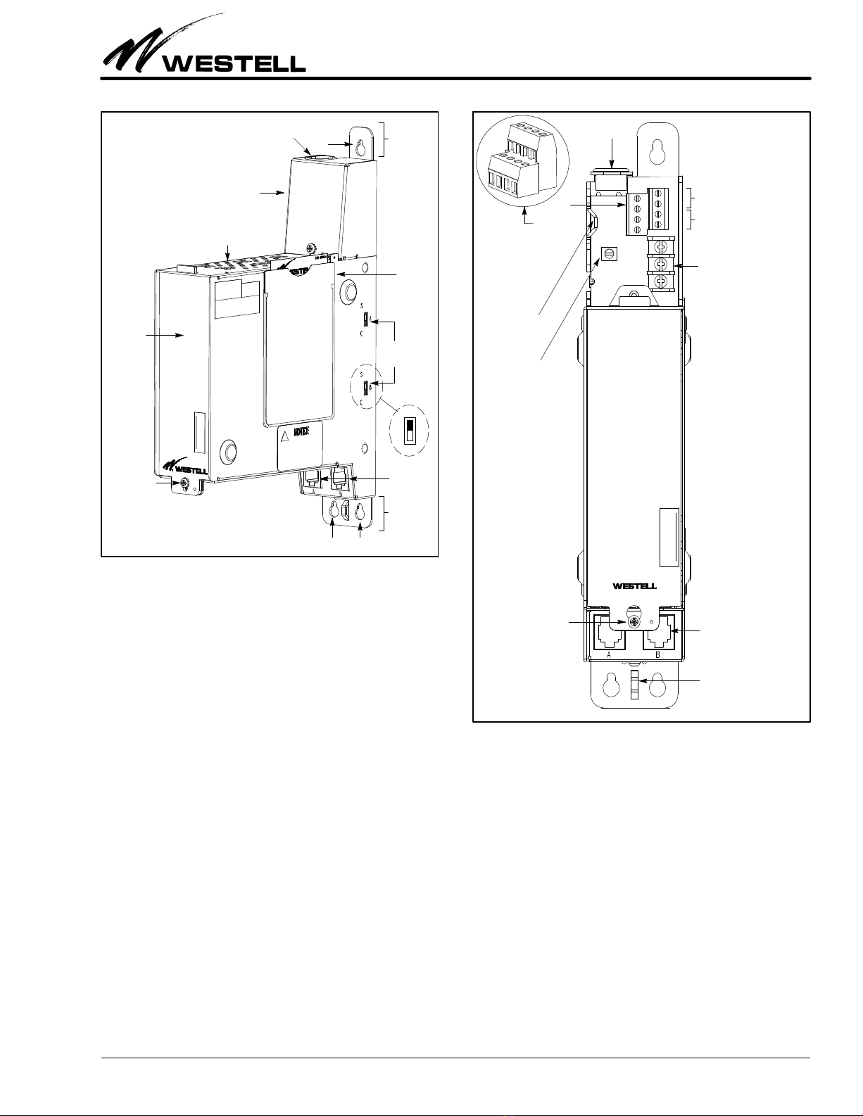
3.4.3 Facility/Network Interface Connections
Facility connections are made to two screw‐type, 4‐position con
nectors (Paragraph 2.2.2) in the Facility wiring compartment at
the top of the 28MA202. The specific type of connector varies
with the specific model ordered (see Table 1 and Figure 3). Pin
designations are shown in Figure 6, the wiring diagram. Route
wires through the grommet at the top of the 28MA202, dress and
secure wires to the connector per company practice, and secure
the wires to the cable tie‐down on the 28MA202 with the cable
ties provided, when complete (after testing).
3.4.4 Customer Interface Connections
Customer interface connections are made to one or both
RJ48C/S jacks at the bottom of the 28MA202. The specific type
of connector is determined by the application and the setting of
the operation mode switch(es) on the side of the 28MA202 (see
Paragraphs 2.1.3 and 2.1.4, and Figure 2). Pin designations are
shown in Figure 6, the wiring diagram. After testing, cables may
be secured to the 28MA202 at the cable tie‐down with the cable
ties provided.
3.4.5 Module Installation
Both 200 MECHANICSand 400‐type plug‐in modules can be
inserted into the 28MA202 after the mounting installation is
complete. The modules make electrical connection when
installed and properly seated in the card‐edge connector of the
28MA202. Before installing any module, set any option
switch(es) to the desired position(s). Align the module with the
mounting card guides above and below the unit and insert as far
as it will go into the slot connector.
‐ CAUTION ‐
Use care when installing and removing modules ‐ do not force
a module into place. If a module resists insertion, remove it
and check for obstructions in or near the connectors and
mounting slots and gently re‐insert the module.
4. TESTING & TROUBLESHOOTING
4.1 Testing
This equipment should not be field repaired. If the equipment
is suspected of being faulty, replace it with another unit, op
tioned identically, and retest. If the replacement unit appears to
operate correctly, the original unit may be faulty and should be
returned to Westell for repair or replacement (Paragraph 6.2).
4.2 Troubleshooting
If trouble is encountered, verify all installer connections to the
or mounting and check that the CO power fuse is not blown. Also
verify all module connections, option switch settings, the mount
ing's side switch settings, and verify the modules are making a
positive connection with the shelf connector. If trouble persists,
replace the suspect unit and repeat procedures outlined. These
procedures are not designed to effect repairs or modifications.
Any tests beyond those outlined herein, or repairs made beyond
replacing a faulty unit, are not recommended and may void the
warranty.
5. CUSTOMER & TECHNICAL SERVICES
5.1 Customer Service & Technical Assistance
If technical or customer assistance is required, contact Westell
by calling or using one of the following options:
Voice: (800) 377‐8766
email: [email protected]
For additional information about Westell, visit the Westell
World Wide Web site at http://www.Westell.com.
5.2 Part Numbers
This equipment is identified by a product number
(C90‐28MA202X), which consists of three parts: the issue letter
of the equipment (C), the assembly type (90), and the specific
model number (28MA202X). Each time a change is made to the
product which changes the form, fit, or function of the product,
the issue letter is incremented or advanced by one. Be sure to in
dicate the issue level as well as the model number when making
inquiries about the equipment.
6. WARRANTY & REPAIRS
6.1 Warranty
Westell warrants this product to be free of defects at the time of
shipment. Westell also warrants this product to be fully func
tional for the time period specified by the terms and conditions
governing the sale of the product. Any attempt to repair or
modify the equipment by anyone other than an authorized Wes
tell representative will void the warranty.
6.2 Repair and Return
Westell will repair or replace any defective Westell equipment
without cost during the warranty period if the unit is defective
for any reason other than abuse, improper use, or improper
installation. To return defective equipment, first request a Re
turn Material Authorization (RMA) number from Westell by
calling or using one of the options shown below. Once an RMA
number is obtained, return the defective unit (freight prepaid),
along with a brief problem description, to the address we will
provide to you when you contact us.
Voice: (630) 375‐4457
email: [email protected]
Replacements will be shipped in the fastest manner consistent
with the urgency of the situation. Westell will continue to repair
or replace faulty equipment beyond the warranty period for a
nominal charge. Contact Westell for details.

Section 28M‐A20‐200‐20C 030‐101670 Rev. C
1205ICRC
8
‐ TL9000 RECYCLING NOTE ‐
Westell recommends that its products be recycled at the end of their
product life. For Westell products that have reached their product End Of
Life (EOL), please recycle and dispose of the products per your company
practice, per local recycling programs and local codes, and per state
statutes.
7. SPECIFICATIONS
7.1 Ordering Specifications
To order units, call the telephone number shown in Paragraph
5.1 and please specify a specific model number shown in Table 1.
7.2 Electrical, Regulatory and Physical Specifica
tions
The electrical, physical, and regulatory agency specifications are
shown in Table 2.
Physical Feature U.S. Metric
Height 9 inches 23cm
Width 2 inches 5 cm
Depth 7 inches 18 cm
Weight (approx.) 2 pounds 0.9 Kilogram
Operating Temp. 0°to 122°F ‐18°to 50°C
Humidity 5 to 95% (non‐condensing)
Mounting Typically wall‐mounted. Also available is a
Wall‐Mounting Kit (see Table 1).
Module Capacity Two 200 MECHANICStype plug‐in units or
one 400‐type plug‐in unit such as a T1 NIU,
an HDSL Remote unit, a DDS‐NIU or other
equivalent unit
Electrical Specifications
Power Supply (P versions only): A90‐204100: 1.25 A at ‐48 VDC,
output; 117 VAC input.
Regulatory/Agency Specifications
UL Performance Criteria: UL Listed with load currents of 2 Amps
or less with power supplies whose inputs are 117 VAC, 60 Hz
(nominal)
NEBS Level 3 compliant.
Table 2. Physical Specifications
8. ACRONYMS & ABBREVIATIONS
The following acronyms, abbreviations, and trademarks are
found in this practice.
C ‐ Celsius
CLEI CLEIis a trademark of Telcordia Technologies
cm ‐ Centimeter
CPE ‐ Customer Premise Equipment
DDS ‐ Digital Data Systems
F ‐ Fahrenheit
GND ‐ Ground
HDSL ‐ High‐bit‐rate Digital Subscriber Line
Hz ‐ Hertz
Kb/s ‐ Kilobits per second
LEDs ‐ Light Emitting Diode
mA ‐ Milliampere(s)
NEBS ‐ Network Equipment Building Standards
NIU ‐ Network Interface Unit
NRTL ‐ Nationally Recognized Testing Laboratory
PWR ‐ Power
RCV ‐ Receive
RMA ‐ Return Materials Authorization
UL ‐ Underwriter's Laboratories
V ‐ Volt(s)
VAC ‐ Volts Alternating Current
VDC ‐ Volts Direct Current
XMT ‐ Transmit
This manual suits for next models
6
Table of contents
Other Westell Industrial Equipment manuals