Page 2
1. GENERAL DESCRIPTION
1.1. The NPGMT1122 Fuse Panel provides up
to 10 circuits for the distribution of DC power to
equipment. Each of the 10 circuits is
individually protected by a GMT style
telecommunication fuse located on the panel's
faceplate. Alarm circuits are provided to
indicate and extend alarm conditions when
faults occur. Normal Operation LEDs are
provided to indicate the status of each bus in
the panel.
1.2. Input wiring is connected to a high current,
2-hole lug input block located on the front of the
panel.
1.3. The power is distributed to the load side
equipment through GMT style fuses. There are
a total of 10 fuses per panel. (See Figure 3.2.1)
Each fuse position is available for installer
connection on the front of the panel. (See
Figure 4.5.1) A designation card is provided for
keeping records of which position is connected
to which equipment and what amperage is to
be used.
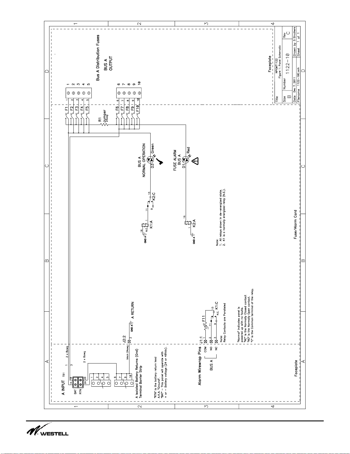
1.4. Alarm circuits are provided to alert service
personnel of fault conditions. A fuse alarm is
caused when any of the GMT distribution fuses
opens. A red fuse alarm !LED on the
faceplate will illuminate and the green Normal
Operation 9 LED will extinguish to signal a
fuse alarm and also the appropriate relay
contacts will change states. (See Figure 3.2.1)
The fuse panel has common (C), normally
open (NO) and normally closed (NC) terminals
for alarms. Note, the use of the alarm
contacts is optional, if you do not wish to
extend the alarms, you don’t have to do
anything with the alarm pins. (See Figure
4.7.1)
The “Normal” condition of the relay exists when
the panel is powered up without any blown
fuses.
If input power is lost the 9 LED will extinguish
and the alarm relay will indicate an alarm.
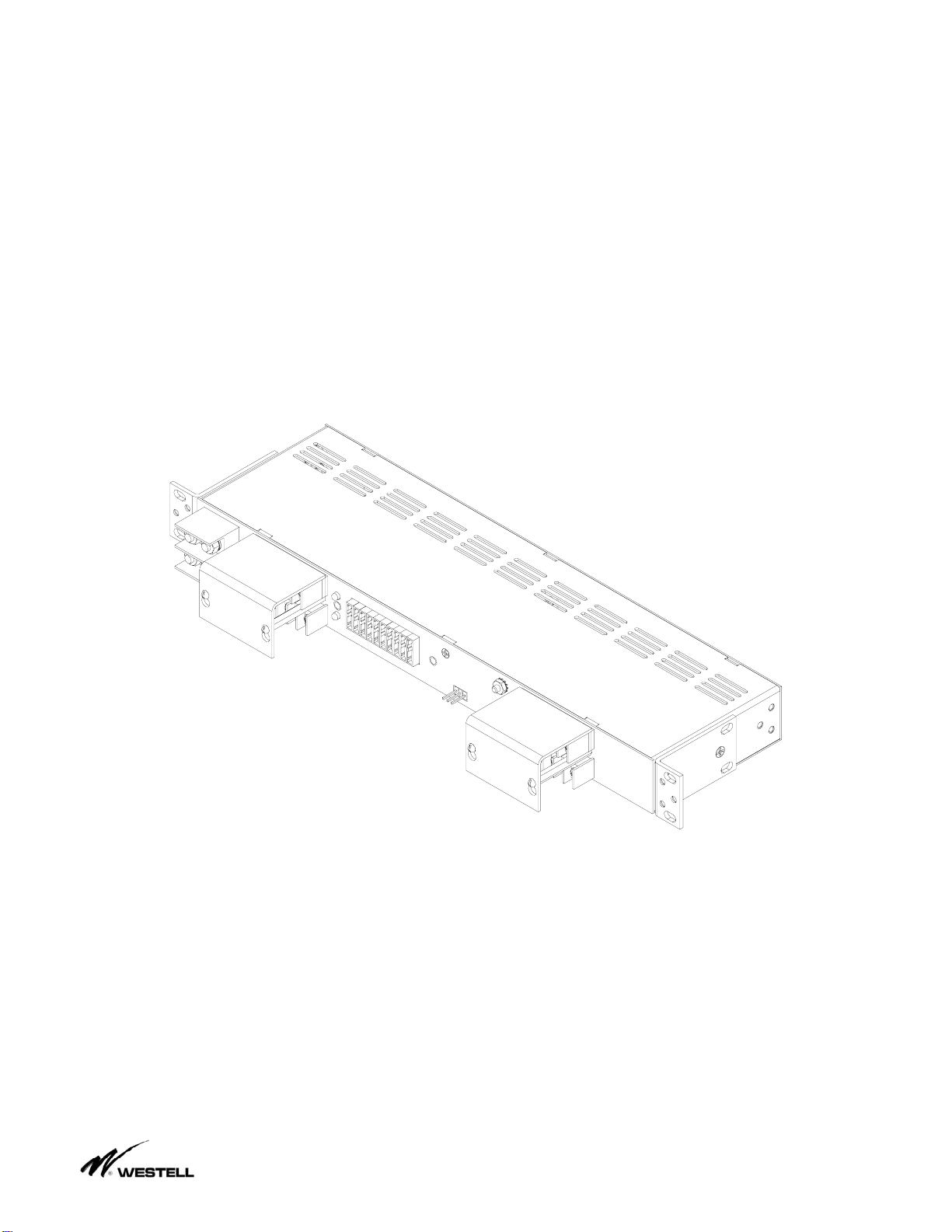
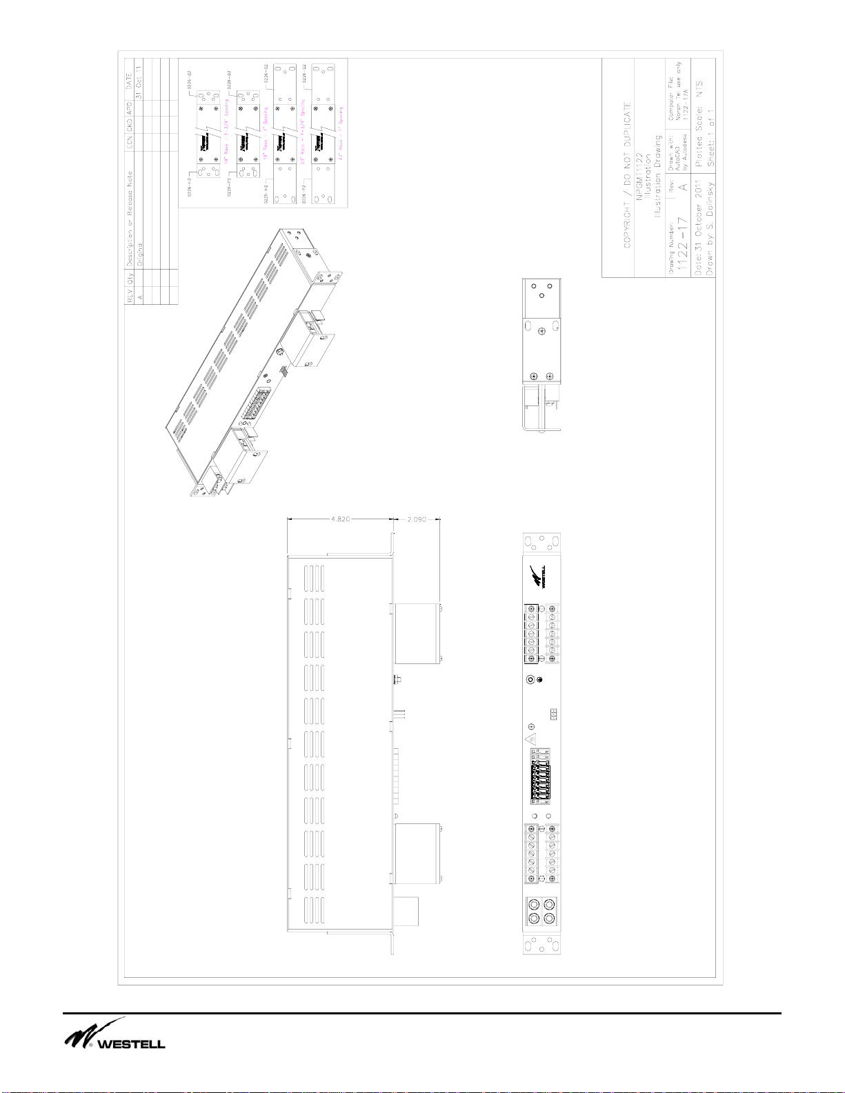
1.5. The NPGMT1122 fuse panel is made from
0.050" steel and painted off white. This panel is
shipped universal brackets that will fit both 19"
and 23" wide racks and uses only one 1.75"
panel spaces. The panel has two clear L
shaped shields to protect the wiring
connections on the front of the panel. (See
Figure 1.6.1)
Figure 1.6.1
2. APPLICATION
2.1. The NPGMT1122 Fuse Panel is designed
to be used in the distribution of DC power.
They are rack mount panels that can provide
fused DC power to up to 10 individual circuits.
3. CIRCUIT DESCRIPTION
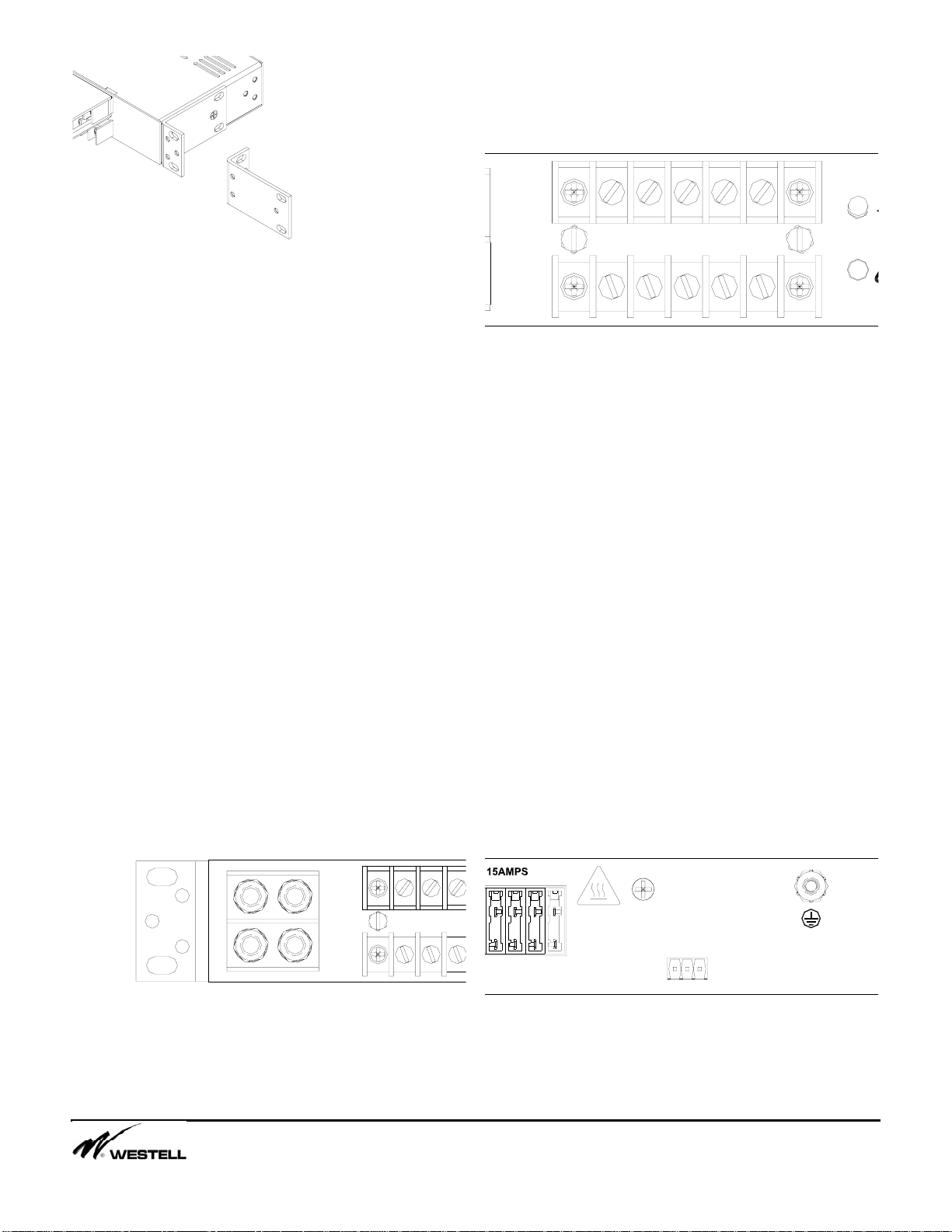
3.1. Power is connected to the fuse panel via
¼” studs on 5/8” centers located on the front of
the panel (Torque 36 in-lbs). This input is a
high current stud block that supplies current to
the fuse panel. Connect the battery return
cable to the stud input that is labeled “RTN”
and the Battery supply cable is connected to
the terminals labeled “BAT”.
3.2. Distribution of current is provided by GMT
style fuses. Each panel has 10 fuse holders for
distribution, the fuses are labeled 1 to 10.
(See Figure 3.2.1) Each fuse position is made
available on the front of the fuse panel.
Maximum output current of each fused position
is 10.5 Amps for a 15 Amp fuse. The input
must be fused at the BDFB at 100Amps max.
Load current should not exceed 70% of the
fuse capacity. Fuses should be sized at at
least 1.5 times the maximum current draw of
the equipment.