Westell NPTPA1105 Instructions for use

____________________________________________________________________________________
Westell
030-000210 Rev F
1105-03F
August 2012
Westell
Fuse Panel
Technical Practice
NPTPA1105
4/4 TPA &6/6 GMT
NEBS Level 3 Verified
FEATURES
Compatible with +24V, +48V, -24V or -48V dc input voltages (battery voltages).
2 busses per panel (160 Amps/bus maximum).
6 GMT style fuses per bus (20 Amps/GMT max, 50 Amps per GMT bus max).
4 TPA style fuses per bus (50 Amps/TPA max, 120 Amps per TPA bus max).
Normal and Alarm LEDs for Bus A and Bus B indicate power or fuse failure.
Two sets of “Form C” relay contacts extend alarm conditions for each bus.
Brackets supplied are reversible for both 19” and 23” racks.
High current 1/4” stud inputs (1/4”studs on 5/8” centers) for up to 160 Amps/input.
Offset terminal blocks with rear shield provided (standard).
NEBS level 3 verified, with zone 4 earthquake.
UL Listed

____________________________________________________________________________________
Westell
2
1. GENERAL DESCRIPTION
1.1. The Westell NPTPA1105 Fuse Panel
provides fused distribution of DC power to
equipment. The panel has 2 buses, each bus
consisting of 6 GMT style fuse positions and 4
TPA style fuse positions. Alarm circuits are
provided to indicate and extend alarm
conditions when faults occur.
1.2. Wiring for the panel is connected to easy
access terminal blocks on the back of the
panel. Alarms are connected via wire-wrap
connectors on the back of the panel.
1.3. The power is distributed to the load side
equipment through GMT and TPA style fuses.
There are 6 GMT style fuses per bus and 4
TPA style fuses per bus. The GMT fuses are
20 Amps max. each, or 50 Amps max. per
GMT group for each bus. The TPA fuses are
50 Amps max. each, with a maximum rating of
150 Amps of TPA fuses per bus. Therefore
the total Amps per input, including TPA and
GMT fuses, is 160 Amps. A designation card
is provided for keeping records of which
position is connected to which equipment and
what amperage of fuse is to be used.
1.4. Alarm circuits are provided to alert
service personnel of fault conditions. A fuse
alarm is a blown fuse (GMT or TPA) within a
given bus. A red Fuse Alarm LED
!
on the
faceplate will illuminate when an alarm
condition is present. As well, the green Normal
Operation LED will extinguish to signal a
fuse alarm or input power failure and the
appropriate relay contacts will change states.
These fuse panels have common (C),
normally open (NO) and normally closed (NC)
terminals for alarms. Note, the use of the
alarm contacts is optional, if you do not wish to
extend the alarms, you don’t have to do
anything with the alarm pins. The “Normal”
condition of the relay exists when the panel is
powered up without any blown fuses. The
local alarm LEDs are located on the front of
the panel as shown in Figure 1.4.1
LED SYMBOL SIGNIFICANCE
GREEN NORMAL
OPERATION
RED
!
BLOWN FUSE
GMT GMT
7 8 9 10
48 VDC
24 VDC POS NEG
5 6 7
Noran Tel
By
!
!
Figure 1.4.1
1.5. The Fuse Panel is made from 0.050” steel
and painted off-white. The panel is shipped
with universal mounting brackets that fit both
19” and 23” wide racks. Brackets for both
1.75” and 1” panel spaces are shipped with
each panel.
2. APPLICATION
2.1. The NPTPA1105 Fuse Panel is designed
to be used in the rack level distribution of DC
power. They are rack mount panels that
provide fused DC power through two busses;
each bus has 6 GMT style fuses, and 4 TPA
style fuses per bus.
2.2 The NPTPA family of fuse panels are
suitable for installation as part of a Common
Bonding Network (CBN). As well this family of
fuse panels is suitable for restricted access
locations in Network Telecommunications
Facilities, and OSP.
3. CIRCUIT DESCRIPTION
3.1. Power is connected to the panel through
1/4” stud input blocks (see fig 3.1.1). There is
one set of inputs for each bus. These inputs
are high current terminals with a maximum
continuous current of 160 Amps. There is a
Return (RTN) and Battery (BAT) input for each
bus.

____________________________________________________________________________________
Westell
3
10 9
BAT
B
RTN 10 9
TRQ nuts to 5.5 ft-lbs max
Figure 3.1.1
3.2. Distribution of current from each bus is
provided by GMT and TPA style fuses. Each
bus has 6 GMT fuses and 4 TPA fuses. Each
fuse position is made available at the rear of
the panel via #6 screw terminal blocks. The
GMT fuses for both bus A and bus B are
numbered 5 thru 10. The TPA fuses are
numbered 1 thru 4 for bus A and bus B.
3.3. Fuse alarm contacts are located on the
back panel on wire wrap terminals. Two sets
of dry contacts are provided, one for each of
the busses.
3.4. Bus alarm circuitry provides dry “Form C”
contacts for alarm extensions. In the event of
an alarm or an input power failure, the relay
falls back, making a connection between
common (C) and normally open (NO). When
there is no alarm, there is a connection
between common (C) and normally closed
(NC). Note: There is one set of contacts for
Bus A and one set for Bus B alarms.
4. INSTALLATION
Please read completely before beginning.
WARNING: Installation should only be
performed by an experienced Installer familiar
with DC power distribution systems.
This product must be installed within a
RESTRICTED ACCESS LOCATION where
access is through the use of a tool, lock
and key, or other means of security, and is
controlled by the authority responsible for
the location. This product must be
installed and maintained by TRAINED
SERVICE PERSONNEL ONLY.
Rack Mount Instructions:
Elevated Operating Ambient - For closed or
multi-unit rack assemblies, the operating
ambient may be greater than room ambient.
Take care to install the equipment in an
environment compatible with the maximum
ambient temperature (Tma) specified by the
manufacturer.
Reduced air flow - Installation of the
equipment in a rack should be such that the
amount of air flow required for safe operation
is not compromised.
Mechanical Loading - Mounting of the
equipment in the rack should be such that a
hazardous condition is not achieved due to
uneven mechanical loading.
Circuit Overloading - Consideration should
be given to the connection of the equipment to
the supply circuit and the effect that
overloading of the circuits might have on
overcurrent protection and supply wiring.
Appropriate consideration of equipment
nameplate ratings should be used when
addressing this concern.
Reliable earthing - Reliable earthing of rack-
mounted equipment should be maintained.
Particular attention should be given to supply
connections other than direct connections to
the branch circuit.
4.1. Unpack and inspect the Westell Fuse
Panel for possible damage incurred during
shipping. If damage is found, please file a
claim immediately with the carrier and notify
Westell Customer Service of the damage.
4.2. Once the panel is unpacked, verify that
there are three mounting brackets. The
bracket with the vertical slot is used on both 1”
and 1-3/4” spacing. All three brackets are

____________________________________________________________________________________
Westell
4
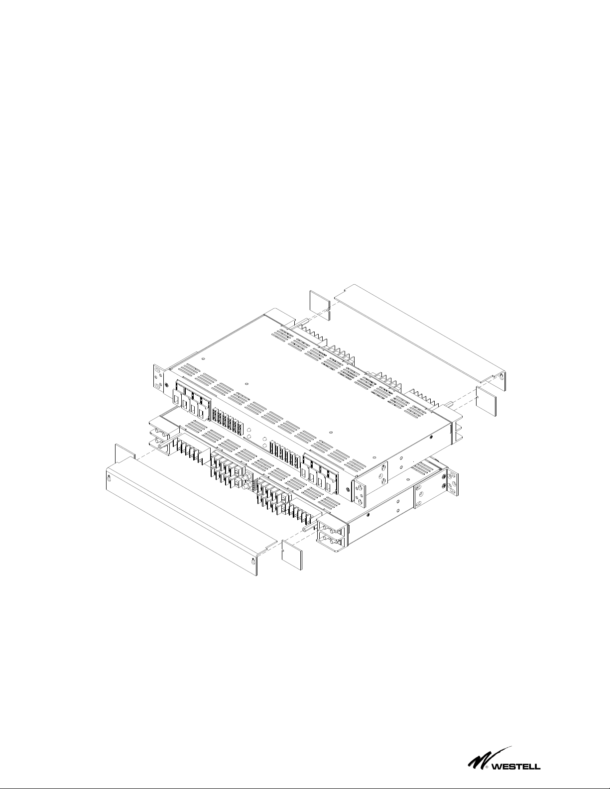
universal for 19” and 23” rack mount spacing
(see figure 4.2.1) and can be mounted so the
panel can be installed for a flush mounting or
5” offset. Adjust the position and orientation of
the correct mounting brackets on the fuse
panel, such that it will fit the rack you wish to
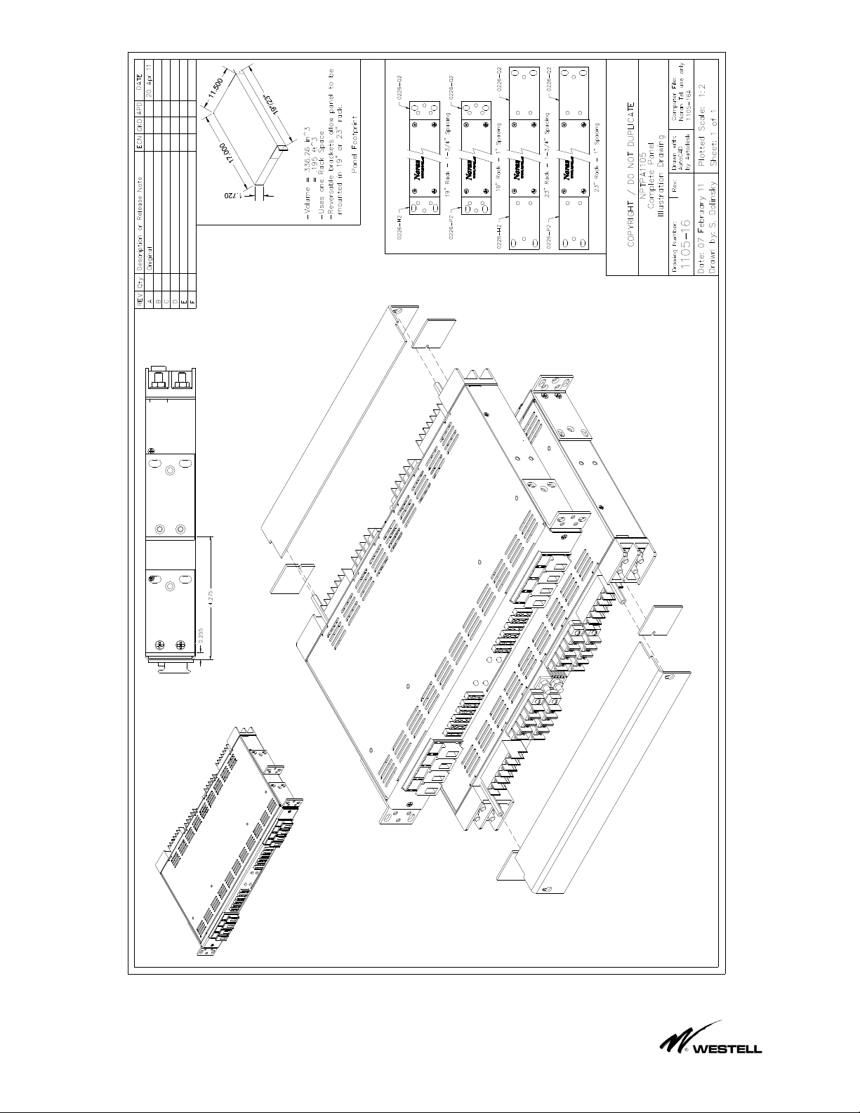
mount the panel in. Please see drawing 1105-
16 on page 8 for mounting bracket
configuration.
19" Mounting Position
23" Mounting Position
Figure 4.2.1
4.3. Mount the fuse panel in the required
position on the rack using the thread forming
rack screws and tooth lock washers provided.
WARNING:For safety reasons, all wiring
should be performed with the power source
removed, and performed by a trained Installer
experienced with DC power systems.
Note: A readily accessible disconnect device
shall be incorporated in the building
installation wiring.
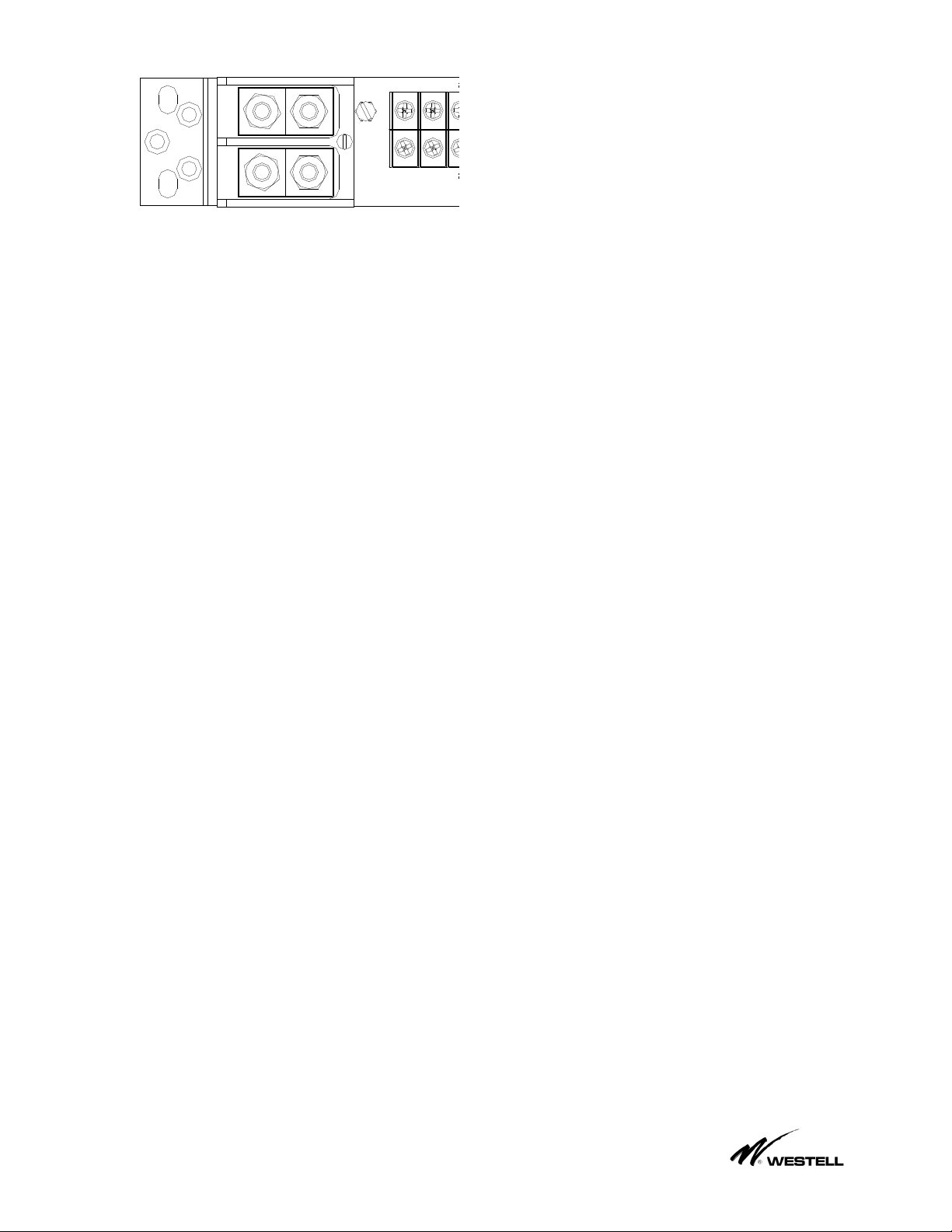
4.4. Remove the distribution fuse feeding the
input cables that are to be connected to the
new panel. Attach the input cables to the
input terminal block in accordance to the
National Electrical Code, ANSI/NFPA, and
Canadian Electrical code. Hook up the input
cables to the input terminal block on the fuse
panel (“BAT” & “RTN” for each bus). Each
high current input terminal uses a two hole
compression lug (1/4” on 5/8”, torque to 5.5 ft-
lbs). A two hole lug must be used for proper
operation
4.5. The fused battery outputs (BAT) and
ground returns (RTN) are also located on the
back of the panel. Each fuse holder and
terminal position is individually numbered.
Connect your load side equipment to the fuse
panel, and record which equipment is
connected to which input on the designation
card (supplied).
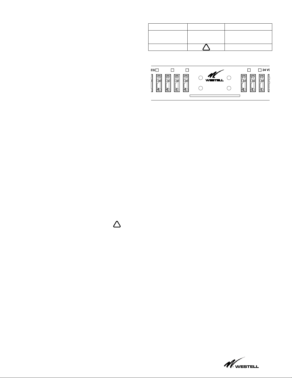
4.6. Alarms; There are three connections for
each of the alarm relays; common (C),
normally open (NO), and normally closed
(NC). Connect the alarm extension wires as
per your alarming scheme (22 or 24awg
typical). Example; Connect the signal that you
want extended in an alarm condition to the “C”
pin. When there’s an alarm, “C” will become
shorted to “NO”. Typically a ground is
connected to the “C”, and the “N.O.” signal is
extended to the alarm monitoring system,
providing a “Ground Alarm”. A “Bus Alarm” is
caused by a fuse failure or an input power
failure on that bus. “Normal” indicates the
state when the panel is powered up with no
blown fuses. The three relay contacts are dry,
so you can parallel the contacts, etc. Please
limit the current thru the relays to 1Amp or less
(Alarm Battery Supply fuse should be 1 Amp
max). Alarm extensions discussed above, are
optional; only use them if you wish (see 3.4 for
details).
4.7. Chassis Ground; for safety reasons, the
chassis should be electrically connected to the
rack ground. From step 4.3, the panel should
already be bonded to the rack via the #12-24
thread forming rack screws and outside tooth
lock washers. In addition to grounding via the
mounting brackets, an appropriate cable size
as outlined in section 5 (typically 10awg or
larger) and the ¼” bolt and locks on rear of
chassis (1/4” bolt torque;5.5ft-lbs or 7.5Nm)
should also be used. Consult the National
Electric Code, ANSI/NFPA, and Canadian
Electrical code for AWG sizes.
4.8. The input wiring feeding this panel should
be protected by a Listed fuse/breaker rated for

____________________________________________________________________________________
Westell
5
at least 60Vdc, with a trip rating of 200 Amps
Max. With input wiring connected and this
input fuse installed, the panel should power up
with the Normal Operation LED illuminated
and without any red LEDs
!
illuminated,
and the relays should be in the “Normal” state
(“C” connected to “NC”).
4.9. If you wish to verify the fuse alarm circuit,
you can insert a blown fuse into one of the
empty fuse holders. The red Fuse Alarm
LED
!
should light and the Normal
Operation LED should extinguish and the
appropriate alarm extension relay should
change states to extend the alarm.
4.10. Install panel output distribution fuses as
required. Be sure to size fuses to no more
than 70% of their rating (14A max for a 20A
fuse) for a GMT fuse, and 80% for a TPA style
fuse. Fuses are not included with this panel.
Fuse ratings should be selected to match the
load equipment ratings. Once the appropriate
fuses have been selected, the fuse information
for F1-F10 on BUS A and F1-F10 on BUS B is
to be recorded at the time of installation. Use
the provided designation card to keep a record
of which equipment is connected to which
circuit and what the fuse rating is. Be careful
not to overload the panel bus or BDFB fuse
position rating supplying the panel.
4.11 Install amperage marking labels as
required below each fuse for identification of
circuit rating (see fig 1.4.1). For fuse color
codes please see table 4.11.1 below. Contact
Westell for amperage marking labels.
Amps Color Code
18/100
A
Yellow
2/10 A Red/Black
1/4 A Violet
3/8 A Gray/White
1/2 A Red
65/100
A
Black
3/4 A Brown
1 A Gray
1 1/3 A White
1 1/2 A White/Yellow
2 A Orange
2 1/2 A White/Orange
3 A Blue
3 1/2 A White/Blue
4 A White/Brown
5 A Green
7 1/2 A Black/White
10 A Red/White
12 A Yellow/Green
15 A Red/Blue
20 A Green/White
Table 4.11.1

____________________________________________________________________________________
Westell
6
5. SPECIFICATIONS
5.1. Voltage -/+24 or -/+48 VDC Typical
-/+22 to -/+58 VDC Max.
5.2. GMT Fuse Size 0.18 to 20 Amps Max*
450A @60Vdc Interrupt rating
(Littelfuse Type 481 Series)
5.3. TPA Fuse Size 3 to 50 Amps Max*
Rated 170 Volts DC
Interrupt Rating: 100kA
(Bussmann TPA style fuse)
5.4. Current/GMT Bus 50 Amps Max**
5.5. Current/TPA Bus 120 Amps Max**
5.6. Current/Input 160 Amps Max (fuse at 200A)
5.7. Output/Bus 4 TPA & 6 GMT
5.8. Busses/Panel 2 Busses per Panel
5.9. Input Block Two ¼” Studs on 5/8 centers
Max std lug is 1 AWG
Max lug width = 0.710”
5.10. GMT Output #22 AWG to 12 AWG wire
Or fork/ring for #6 screw,
10AWG forks/rings will work
5.11. TPA Output #20 AWG to 10 AWG wire
6 AWG & 8 AWG with narrow
tongue lug (#6 screws)
Max lug width = 0.375”
5.12. Alarm Block 0.045” sq wire wrap pin
5.13. Relay Current 1 Amp/58Vdc max
5.14. Dimensions 1¾ H, 17 W,10½ D
(excluding brackets
5.15. Rack Mounting 19” and 23” Racks
1” and 1.75” spacing
5.16. Weight Approx 10 lbs
5.17. Operating Temp. -40 to +55C (Tma)
(-40 to +131F)
5.18. Color Off-white
5.19. Short Circuit 450A (Max)
Withstand Rating
*We recommend that you size GMT fuses such that
they do not run at more than 70% of their rating. Thus
a 20A fuse should not be run at more than 14 A. TPA
fuses should be sized such that they do not run at
more than 80% of their rating.
**The sum of the fuse ratings must not exceed the bus
rating.
Table 1.1: Terminal Block Designations
FUNCTION DESIGNATION
Inputs A Bus Battery A BAT
(on stud input block) A Bus Return A RTN
B Bus Battery B BAT
B Bus Return B RTN
TPA Outputs A Bus Battery 1-4 TPA BAT (Bus A side – Top Row)
A Bus Return 1-4 TPA RTN (Bus A side – Bottom Row)
B Bus Battery 1-4 TPA BAT (Bus B side - Top Row)
B Bus Return 1-4 TPA RTN (Bus B side – Bottom Row)
GMT Outputs A Bus Battery 5-10 GMT BAT (Bus A side – Top Row)
A Bus Return 5-10 GMT RTN (Bus A side – Bottom Row)
B Bus Battery 5-10 GMT BAT (Bus B side – Top Row)
B Bus Return 5-10 GMT RTN (Bus B side – Bottom Row)
Alarms (wire-wrap pins)
Bus A Alarm - Relay Contact - Common BUS A C
Bus A Alarm - Relay Contact - Normally Open BUS A NO
Bus A Alarm - Relay Contact - Normally Closed BUS A NC
Bus B Alarm - Relay Contact - Common BUS B C
Bus B Alarm - Relay Contact - Normally Open BUS B NO
Bus B Alarm - Relay Contact - Normally Closed BUS B NC
Note; The “Normal” condition exists when the panel is powered up without any blown fuses.

____________________________________________________________________________________
Westell
7
Compatible lugs for Input Block
2 hole compression lugs for 1/4” studs on
5/8” centers (torque 5.5ft-lbs) example;
Panduit® LCDN2/0-14A (2/0 wire narrow)
LCD1-14A 1awg wire
LCD2-14A 2awg wire
LCD4-14A 4awg wire
LCD6-14A 6awg wire
LCD8-14A 8awg wire
The Panduit® CT-1700 crimping tool can be
used for securing wire to any of these lugs.
Input wiring should be rated 90°C or better
and fused at 125% of total Bus current (ie: up
to 200Amps MAX rated input fuse/breaker)
For currents over 100Amps, input wiring
should be rated 130°C or better.
Output lugs (locking fork recommended):
Ring or fork for #6 screw (up to 10awg).
(Torque to 9 in-lbs, use wire rated 90°C or
better.
Or “Narrow Tongue” ring lugs by Burndy,
for the cables large cables and the TPA
blocks;
Burndy# YA8CLNT6 (8 awg wire)
NOTE: If fuse size is not specified in the
equipment manual, fuses should be selected
such that they do not run at more than 70%
for GMT’s and 80% for TPA’s, of their rating.
When installing fuses, the sum of the fuses
installed in each bus should not exceed the
bus input rating (160 Amps) or input fuse
rating.
Chassis Grounding: Depending on the bus input current being supplied, the chassis bonding
conductor used should meet the minimum requirements. Please note that 160 A is the maximum
allowable bus current rating.
Protective Current
Rating Minimum AWG Recommended
Compression Lug
Minimum Wire
Temperature rating
0-40 Amps 10 AWG Panduit, LCD10-14A 90°C
40-63 Amps 8 AWG Panduit, LCD8-14A 90°C
63-80 Amps 6 AWG Panduit, LCD6-14A 90°C
80-100 Amps 4 AWG Panduit, LCD4-14A 90°C
100-125 Amps 2 AWG Panduit, LCD2-14A 90°C
125-160 Amps 1 AWG Panduit, LCD1-14A 90°C

____________________________________________________________________________________
Westell
8
6. TECHNICAL SERVICES
6.1 If technical or customer assistance is
required, contact Westell by calling or using
one of the following options:
Voice: (800) 377-8766
For additional information about Westell, visit
the Westell World Wide Web site at
http://www.Westell.com.
7. WARRANTY & REPAIRS
7.1 Westell warrants this product to be free of
defects at the time of shipment. Westell also
warrants this product to be fully functional for
the time period specified by the terms and
conditions governing the sale of the product.
Any attempt to repair or modify the equipment
by anyone other than an authorized Westell
representative will void the warranty.
7.2 Westell will repair or replace any defective
Westell equipment without cost during the
warranty period if the unit is defective for any
reason other than abuse, improper use, or
improper installation. To return defective
equipment, first request a Return Material
Authorization (RMA) number from Westell by
calling or using one of the options shown
below. Once an RMA number is obtained,
return the defective unit (freight prepaid), along
with a brief problem description, to the address
we will provide to you when you contact us.
Replacements will be shipped in the fastest
manner consistent with the urgency of the
situation. Westell will continue to repair or
replace faulty equipment beyond the warranty
period for a nominal charge. Contact Westell
for details.

____________________________________________________________________________________
Westell
9
Noran Tel
Mounting Options
5 " OFFSET MOUNTING
FLUSH MOUNTING

____________________________________________________________________________________
Westell
10
Noran Tel
TPA
1 4
GMT GMT
4
TPA
5 6 7 8 9 10
POS 48 VDCNEG 24 VDC POS 48 VDCNEG 24 VDC
1
5 6 7 8 9 10
1234
B
C
NC
NO
BUS A
C
NC
NO
BUS B
ALARMS
10 9 8 7 6 5 10 9 8 76 5
1234
BAT
RTN
A
BAT
RTN
TPA TPA
BAT BAT
B
RTN
A
RTN
GMT
10 9 8 7 6 5
GMT
10 9 8 7 6 5
Noran Tel
By
!
!
TRQ nuts to 5.5 ft-lbs maxTRQ nuts to 5.5 ft-lbs max
50A MAX TPA FUSE
BUS
A
BUS
A

____________________________________________________________________________________
Westell
11
Noran Tel
Table of contents
Other Westell Network Hardware manuals
Popular Network Hardware manuals by other brands

Burg Wächter
Burg Wächter BURGcam REC 3510 Quick installation guide

Exablox
Exablox OneBlox 4312 user guide

ITS Telecom
ITS Telecom EKSELANS IPC M300 user manual

SEPTENTRIO
SEPTENTRIO PolaRx5TR reference guide

Enterasys
Enterasys 5G1XX Local Management User’s Guide

D-Link
D-Link DAP-3711 Quick installation guide