Westell Noran Tel SITE VU MINI N04005-SVU/L0806 User manual

Firmware Manual 0806-40A
Version 1.0.x
NoranTel Page 1 of 16
a subsidiary of Westell, Inc
Noran Tel
a subsidiary of Westell, Inc.
SITE VU MINI
N04005-SVU/L0806
Firmware: Local Port / Telnet Configuration
CHASSIS
GND
ON
PWR
OFF BAT GND
Noran Tel
www.norantel.com
10BaseT
ETHERNET
PWR CRIT MAJ MIN UNIT
ALM
OFF RESET
REPROGRAM
CONFIG LOCK
H1
H2
A1+
A2+
A3+
A4+
A5+
A6+
A1-
A2-
A3-
A4-
A5-
A6- REF
D1
D2
D3
D4
ALM
SERVICE
PORT
NEW
DATA
COM
NO
NC
CRT
MAJ
MIN COM
GeneralInformation
This document describes how to configure
SiteVu remote units using the local port
(service port) via USB and/or using the Telnet
option over Ethernet.
Any VT100 compatible Telnet client software
and serial communication software may be
used to communicate to the SiteVu remote unit.
Both configuration options provide a full text-
based user interface for configuring the
SiteVu remote unit. This manual describes
how to configure the SiteVu remote unit using
the Service Port. There are minor differences
between the Service Port and Telnet
configuration options. These differences will be
discussed as required throughout the manual.
The numbers displayed in parentheses (#) after
a title is what a user would type on the SiteVu
remote unit screens to access the submenu.

NoranTel Page 2 of 16
a subsidiary of Westell, Inc
Connections
The Service Port connection requires a
standard USB cable connection from the
SiteVu remote unit to PC or laptop that
contains the serial communication software.
If the SiteVu remote unit is powered when the
USB is connected and the communication
software is running, the user can press the
<Enter> key to display the “Noran Tel SiteVu
Telnet Service Login:” screen.
The user can then type their username and
password. Even though the user is on a
Service Port connection the remote unit creates
a communication block to emulate a partial
Telnet connection to the remote unit.
Similarly, when using the Telnet option to
access the SiteVu remote unit, “Noran Tel
SiteVu Telnet Service Login:” is displayed.
At the login prompt the user can type in the
Username, press <Enter> and then the
Password, press <enter>. After 3 failed login
attempts the connection is dropped. The user
must wait a set amount of time (Security Lock
Out time) before trying to reconnect via Telnet.
After a successful login the Site Vu Main Menu
is displayed.
If 3 failed logins occur for the same username,
the username becomes locked and the failed
login attempt is logged in the security menu. A
user-definable lock message and user-
definable lockout time can be set in the
Security Menu. A user that has access to the
Security menu can unlock all locked users.
More information about this can be found in the
security menu.
Note: The factory default username and password is Norantel. Both
the password and username are case sensitive.
Note: T his assumes a user has already configured the Ethernet
settings, enabled the Telnet option, setup a username and password on
the selected SiteVu remote unit for this connection to be allowed.
Note: Only four Telnet connections are allowed to connect to the
SiteVu remote unit at one given time.
Note: The SiteVu remote unit will disconnect an idle connection
(Telnet or Service Port) once the Inactivity Timeout setting in the
Telnet menu is achieved.

NoranTel Page 3 of 16
a subsidiary of Westell, Inc
Contents
A. SITEVU MAIN MENU.............................................................................................................................4
1. COMMUNICATION SETTINGS MENU (1)..........................................................................................5
1.1ETHERNET SETTINGS MENU (1) ..............................................................................................5
1.2SNMP SETTINGS MENU (2) ....................................................................................................5
1.3NTP SETTINGS MENU (3)........................................................................................................6
1.4TELNET SETTINGS (4)..............................................................................................................6
2.LOG VIEWER (2)..................................................................................................................................6
3.DIGITAL INPUTS (3)............................................................................................................................7
3.1DIGITAL INPUT CONFIGURATION MENU..................................................................................7
4.ANALOG INPUTS (4)...........................................................................................................................8
4.1ANALOG INPUT CONFIGURATION MENU .................................................................................8
5.DIGITAL OUTPUTS (5)........................................................................................................................9
6.CURRENT ALARMS (6)......................................................................................................................9
7.SECURITY (7) .....................................................................................................................................10
7.1USER PROPERTIES MENU (1-5) .............................................................................................10
7.2SECURITY LOG MENU (6)......................................................................................................10
7.3ACCESS CONTROL LIST MENU (7).........................................................................................11
7.4SECURITY LOCKOUT MENU ITEMS (8-10).............................................................................11
8.FILE TRANSFER MENU (TFTP) (8)................................................................................................11
8.1CONFIGURATION FILE SETTINGS (3-5) ..................................................................................11
8.2FIRMWARE FILE SETTINGS (6)...............................................................................................12
8.3LOG FILE SETTINGS (7-8)......................................................................................................12
9.SYSTEM INFORMATION (9)............................................................................................................13
10.SYSTEM PROPERTIES (10) ............................................................................................................13
10.1LCD SCREEN SAVER (1) .......................................................................................................14
11.BATTERY RUNDOWN CONTROL (11) .........................................................................................14
11.1BATTERY RUNDOWN SETTINGS (1-3)....................................................................................14
11.2BATTERY RUNDOWN FILES (4-7) ..........................................................................................14
DOWNLOADING WITH TFTP .................................................................................................................15
DOWNLOADING WITH XMODEM .........................................................................................................15

NoranTel Page 4 of 16
a subsidiary of Westell, Inc
A. SiteVu Main Menu
All the menus have a similar look and feel as
well as try to operate in a consistent manner.
•Numbers between “<” and “>” signs are
action numbers.
•Typing a number and pressing <Enter> will
either bring up a new menu or select a
setting that may be changed.
•When a menu items contain a right arrow
(→) a submenu will open to display more
menu options.
•Text after a colon (:) is the setting for that
item and may be changed by the user.
•Press ESC to back out of submenus
•Press Y or y and <enter> to change settings
•Press N or n and <enter> to discard
changes
•Press Ctrl+B to go to Main Menu
•Press Ctrl+Q to close current connection
When entering a submenu, the previous menus
are displayed on the top row of the serial
communication software screen along with the
current menu the user is viewing. For example,
if the user is viewing the SNMP Settings Menu,
“(Main/Comm_settings)-> SNMP Settings
Menu” is displayed. The text underlined after
the arrow is the current menu. Text inside the
brackets refers to previous menus. The user
can back out of the current menu to return to
these previous menus.
When the user types in a number that is
associated with changing a setting (a menu
item that contains a colon) and presses the
<Enter> key, the menu item selected is
displayed along with its previous setting. Also,
a prompt is displayed for the user to enter a
new value for the setting. This prompt will
contain an example of how to enter a new
value. After the user types or selects the new
setting for the menu item and presses the
<Enter> key, a conformation prompt is
displayed to accept the or discard the change.
The SiteVu Main menu is shown in Figure A-1
and contains the following options:
Figure A-1 Site Vu Mini Main Menu
¾Communication Settings Menu (1)
•Configure the communication options
¾Log Viewer (2)
•View the 1000 most recent alarm events
¾Digital Inputs (3)
•View the status of the digital inputs
•Configure the digital input sensors
¾Analog Inputs (4)
•View the status of the analog inputs
•Configure the analog input sensors
¾Digital Outputs (5)
•View the status of the digital output relay
•Configure the digital output relay
¾Current Alarms (6)
•View all the current active alarms
¾Security (7)
•Configure users and set access levels
•View the security log
•Configure Access Control List (ACL)
¾File Transfer Menu (TFTP) (8)
•Setup files for remote firmware upgrade
•Upload and download configuration files
•Download event/security logs
¾System Information (9)
•View extra information
¾System Properties (10)
•Set the time and the remote units name
¾Battery Run-down Files (11)
•Rename and delete files
•Modify Battery Run-down settings

NoranTel Page 5 of 16
a subsidiary of Westell, Inc
1. Communication Settings Menu (1)
When a user types 1 and presses the <enter>
key Figure 1-1 “Communication Settings
Menu” is displayed.
This menu provides submenus for configuring
communication options for the Site Vu.
Figure 1-1 Communications Settings Menu
1.1 Ethernet Settings Menu (1)
This submenu allows a user to configure the
SiteVu remote unit for operation on a network.
Figure 1-2 displays the options that may be
changed on this submenu. These menu items
must be configured to communicate to the
remote unit over Telnet, to have the remote unit
send SNMP traps, and to have the remote unit
communicate to a time server.
Figure 1-2 Ethernet Settings Menu
The Ethernet Remote IP address is a statically
assigned IP address for the Site Vu connected
on the local area network.
The Ethernet Gateway IP address is the IP
address for the gateway on the local area
network that the Site Vu is connected to.
The Ethernet Subnet Mask is the network mask
for the Site Vu connected to the local area
network.
1.2 SNMP Settings Menu (2)
This menu allows the user to configure the
SiteVu remote unit to send SNMP v1 traps to
Network Management Station(s). Figure 1-3
displays the menu item settings for this menu.
Figure 1-3 SNMP Settings Menu
The Allow SNMP Read menu item can be
enabled to allow a user to view the SiteVu’s
information via a SNMP Network Management
Station (NMS).
The SNMP Read Community menu item is the
keyword required at the NMS to view the Site
Vu through the NMS software.
The Site Vu can send events to two SNMP
Trap recipients. A recipient must be enabled in
order for the Site Vu to send traps. An IP
address must be setup for each recipient. The
community string is the keyword that the
associated trap monitor uses. “Send Current
Alarms” allows the user to force any current
alarms out to the SNMP trap manager.
The SNMP Keepalive Trap menu item can be
enabled so the remote unit will send out a trap
to the configured recipients. This trap contains
the remote unit’s name (syslocation) and the
current alarm counts for each severity Level.
The user can define the time interval between 5
minutes and 32,727 minutes (22 days 18 hours
7 minutes). The user can enter a time directly
in minutes (e.g. “300”) or qualify it in days (d),
hours (h) and minutes (m) (e.g. “1d 10h 50 m”)
Note: These menu items can NOT be
changed when using a Telnet session. They
can only be configured when using the
Service Port on the Site Vu remote unit.

NoranTel Page 6 of 16
a subsidiary of Westell, Inc
1.3 NTP Settings Menu (3)
This menu allows the user to configure the
SiteVu to communicate with a network time
server to setup the current Coordinated
Universal Time (UTC) time. Figure 1-4 shows
the menu items available for this submenu.
Figure 1-4 Network Time Settings Menu
When the NTP time server is enabled the
SiteVu will contact any NTP server using
protocol version 4 or 5. The SiteVu will only act
as a client and never a server for the network.
The Time Server IP Address is the IP address
of the time server.
The NTP polling time menu item allows the
user to set the time interval for retrieving a new
time. The user can define any time interval
between 5 minutes and 32,727 minutes (22
days 18 hours 7 minutes). The user can enter
a time directly in minutes (e.g. “300”) or qualify
it in days (d), hours (h) and minutes (m) (e.g.
“1d 10h 50 m”)
1.4 Telnet Settings (4)
This menu allows the user to configure the
SiteVu remote unit to use the Telnet option.
Figure 1-5 displays the menu items for this
submenu.
Figure 1-5 Telnet Settings Menu
The Telnet (terminal over TCP/IP) menu item
may be enabled to allow access to the SiteVu
using a Telnet client from a remote location.
The Telnet Server Port menu item allows the
user to change the default port for the Telnet
server. A user may want to change this port for
access through firewalls and/or to obfuscate
the location of the Telnet server on the SiteVu
remote unit.
The Telnet Inactivity Timeout menu item allows
the user to change how long an idle Telnet
connection stays connected before the SiteVu
drops the connection. The user can define any
time interval between 5 seconds and 32,767
seconds (9 hours, 5minutes, 27 seconds). The
user can enter a time directly in seconds (e.g.
“300”) or qualify it in hours (h), minutes (m),
and seconds (s) (e.g. “1h 30m 35s”).
2. Log Viewer (2)
This submenu allows a user to view the most
recent 1000 event log entries that occurred on
the SiteVu. Figure 2-1 displays an example
screen shot of this menu.
Figure 2-1 Log Viewer Menu
Digital input, analog input and digital output
change state events are displayed using the
Log Viewer. Most recent events are recorded
first. A user can scroll through the log by
pressing <enter>, jump to a log entry by
entering a number and delete all entries by
typing “purge” and then <enter>. The user
must have access (from the Security Menu) to
be able to purge. The log is saved to the
onboard non-volatile memory on the SiteVu.
Note: The Inactivity Timeout controls how
long the Service Port stays connected even if
the Telnet option is disabled.
Note: A user can change these options even
if they are connected through Telnet.
However, any changes will not take effect
until ALL Telnet users are logged out.

NoranTel Page 7 of 16
a subsidiary of Westell, Inc
3. Digital Inputs (3)
This menu allows a user to view the current
digital input states and access to the digital
input configuration menu on the SiteVu remote
unit. Figure 3-1 shows an example of the
digital inputs menu display.
Figure 3-1 Digital Inputs Menu
The sensor number, sensor name and the
current state of the sensor are displayed for all
the digital input sensors on the screen. This
allows a user to see the current input sensor
state levels with out generating an alarm
condition for the input. Any state values other
than “ON” or “OFF” indicate the digital input
sensor is recording alarm events for the input
sensor.
The user can configure a sensor by typing the
number of the sensor and pressing <Enter>.
The following sections discuss the available
configuration options for each digital input.
3.1 Digital Input Configuration Menu
Each digital input can be configured with the
following options as seen in Figure 3-2.
Figure 3-2 Digital Input Configuration Menu
The Sensor Name field can be up to 16
characters. This name will be used when
referring to the sensor in the Log Viewer menu,
for SNMP Traps, etc.
When the Enable Alarm field is enabled the
remote unit will log any changes of state that
occur on the sensor.
The Hysteresis menu item allows the user to
add a de-bounce time to eliminate jitter on the
sensor. This value can be anywhere between
1/10th of a second to 6553.1 seconds (109
minutes). Refer to the Digital Input sensor
section in the hardware manual for more
detailed information.
The Alarm when input is menu item can be set
to ON or OFF. An ON state indicates an alarm
will occur when there is a closed circuit
connection between the sensor and the digital
reference (REF). An OFF state indicates an
alarm will occur when there is an open circuit
connection.
The Severity menu item allows the user to
select a severity states for the sensor. The
severity level options are Critical, Major, Minor,
or Other.
The Send SNMP Trap menu item may be
enabled to allow the Site Vu to send out SNMP
Traps to configured SNMP Trap recipients
each time the sensor changes state.
The ON and OFF Condition Name menu items
allow a user to enter any 12 character condition
name.
The Digital Output Number and Output State
on Alarm menu items allow the user to set up
an automatic control with the SiteVu’s on board
relay (digital output). Only one alarm may
control the digital output relay. When the input
sensor enters an alarm state the selected relay
in the Digital Output Number menu item will
change to the state indicated by the Output
State on Alarm menu item.
The Sensor Description menu item allows the
user to enter any 149 character description of
the sensor.
Note: The digital output relay must be set to
AUTO in the Digital Output menu for
automatic relay control to work.

NoranTel Page 8 of 16
a subsidiary of Westell, Inc
4. Analog Inputs (4)
This menu allows a user to view the current
physical analog input value and event state and
to access the analog input configuration menu.
Analog Input 7 is dedicated to an internal
temperature sensor in the SiteVu. Figure 4-1
shows an example of the analog input menu
screen.
Figure 4-1 Analog Inputs Menu
The user can configure a sensor by typing the
number of sensor and pressing the <Enter>
key. The following sections discuss configuring
the analog inputs.
4.1 Analog Input Configuration Menu
Each analog input can be configured with the
following options as seen in Figure 4-2.
Figure 4-2 Analog Input Configuration Menu
The Sensor Name field can be up to 16
characters. This name will be used when
referring to the sensor in the Log Viewer menu,
SNMP Traps, etc.
The Range, Multiplier, Offset and Unit menu
items allow the user to convert the analog input
voltage to a friendly readable value such as
temperature, current, percentage, etc. The
voltage ranges available include:
•0-125mV
•0-5V
•0-60V
Example 1:
•A user has a 0-400A shunt sensor that
outputs a voltage between 0-50mV.
Rather than displaying a voltage, and
using alarm points in the mV range the
value can be converted to Amperes
instead.
oMultiplier = 400A/50mV = 8000
oRange = 0-125mV
oOffset = 0
oUnits = A (for Amperes)
Example 2:
•A user has a temperature sensor that
outputs 0-5V. The voltage is converted
to Kelvin when it is multiplied by 100.
•F = ((K-273.15)*1.8)+32
•F = ((100*Value-273.15)*1.8+32
•F = 180*value-491.67+32
•F = 180*value + (-459.67)
Therefore the settings would be:
oMultiplier 180
oRange = 0-5V
oOffset = -459.67
oUnits = Fah (for Fahrenheit
The Low Alarm and High Alarm menu items are
used to enable an alarm when the analog
voltage drops below a certain levels or rises
above a certain level.
The Send SNMP Trap menu item can be
enabled to allow the SiteVu to send out SNMP
Traps to configured SNMP Trap recipients
when a low or high alarm event occurs.
The Low Alarm Point and High Alarm Point
menu items allow the user to define the levels
at which an alarm state is occurring.
The Return Point menu items are used to
define when the alarm state returns to a normal
state. The Low alarm return point must be
higher than the low alarm point and the high
return point must be lower than the high alarm
point. Refer to the Analog Input sensor section
in the hardware manual for more detailed
information.

NoranTel Page 9 of 16
a subsidiary of Westell, Inc
The Severity menu item allows the user to set
the alarm state of the sensor to Critical, Major,
Minor or Other. The high and low alarms can
have different severities.
The Digital Output Number and Output State
on Alarm menu items allow the user to set up
an automatic control with the SiteVu’s on board
relay (digital output). Only one alarm may
control the digital output relay. When the input
sensor enters an alarm state the selected relay
in the Digital Output Number menu item will
change to the state indicated by the Output
State on Alarm menu item.
The Sensor Description menu item allows the
user to enter any 149 character description of
the sensor.
5. Digital Outputs (5)
This menu allows the user to configure the
digital output relay on the SiteVu. Figure 5-1
displays the menu options that are available for
configuring the Digital Output Relay.
Figure 5-1 Digital Output Menu
The Sensor Name field can be up to 16
characters. This name will be used when
referring to the sensor in the Log Viewer menu,
for SNMP Traps, etc.
The Current Control State menu item can be
set to SET, CLEAR, and AUTO. The state can
be controlled either manually or automatically
from an analog or digital input. When the state
is SET or CLEAR, the sensor is controlled
manually. When the state is set to AUTO, the
sensor is controlled by an alarm event. When
AUTO is set the state of the relay (SET or
CLEAR) is displayed after the AUTO setting.
When the digital output changes state a SNMP
trap is automatically sent as well as the change
state event is logged.
The Controlling Input menu item can not be
configured from this menu. The Controlling
Input field displays the input sensor that can
control the digital output automatically. By
default the digital output relay is in a manual
control state. Only one alarm event can control
the digital output relay.
The Sensor Description menu item allows the
user to enter any 149 character description of
the Digital Output sensor.
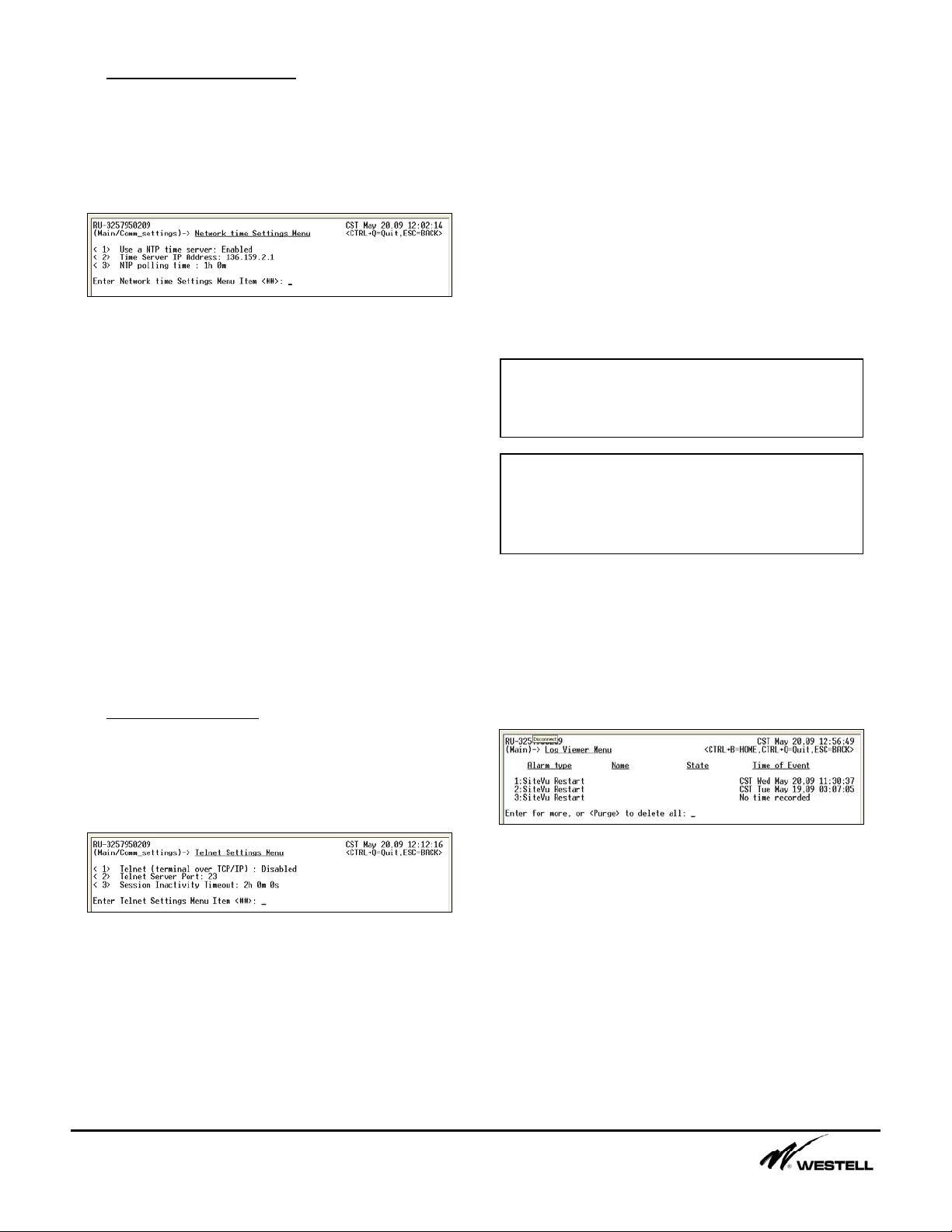
6. Current Alarms (6)
This menu displays the current alarms that are
being reported by the SiteVu. Figure 6-1
shows an example of how the information is
displayed in the menu.
Figure 6-1 Current Alarms Menu
The Current Alarms menu can display up to 18
entries per page. Press the <Enter> key to
view the next page. Pressing the <Enter> key
also refreshes the menu adding any new
Note: Alarm and Return Points are based
upon the range, multiplier, offset, and units
field settings.
Note: The digital output relay must be set to
AUTO in the Digital Output menu for
automatic relay control to work. Note: In order for a digital output to be used
automatically an input sensor alarm must be
configured to control the digital output relay.
Note: The SET state indicates a relay
connection between Normally Open and
Common. The CLEAR state indicates a
relay connection between Normally Closed
and Common.

NoranTel Page 10 of 16
a subsidiary of Westell, Inc
alarms that occurred or removing any alarms
that returned to their normal state.
There are no options on this screen that can be
configured. It is meant to be used as an
informational view-only screen.
7. Security (7)
This menu shows a list of submenus that
allows a user to configure other users for
access to the remote unit, view a security log
for the current remote unit and configure an
access control list for the remote unit. Figure
7-1 displays the submenus available from the
Security menu.
Figure 7-1 Security Menu
7.1 User Properties Menu (1-5)
Up to 5 users can be configured each with
different access privileges. Figure 7-2 shows a
list of all the access privileges that can be set
for each user.
Figure 7-2 User Properties Menu
The Login Name menu item allows new
usernames to be created. A user can be
disabled by entering a blank username. When
a username is entered a prompt for a password
will appear. All keyboard characters are
allowed in the login name and the password.
The remaining menu items allow a user to
configure the privileges for another user. Each
item can be assigned NO ACCESS, READ
ACCESS or READ/WRITE ACCESS. The read
privilege allows that user to view all the menus
in that section. The read and write access
privilege allows a user to read the menus and
change the configuration of the menu items.
The Log Purge Access menu item can be set to
either ACCESS or NO ACCESS. Users with
access will be able to remove all log entries out
of the Security and Alarm Logs.
When access is given to a main menu item, all
submenus associated with that menu will be
accessible as well.
7.2 Security Log Menu (6)
The Security Log menu allows a user to view
any currently logged in users as well as the
past 100 users that logged in. The UTC time,
type of connection, and length of connection is
displayed. A sample Security Log Menu is
shown in Figure 7-3.
Figure 7-3 Security Log Menu
The following abbreviations are used to
describe the connections:
•LOC (Local Port, Service Port)
•TEL (Telnet Connection
•ACT (Active, Current Connection)
The user can press the <Enter> key to scroll
through the log one page at a time.
Alternatively, a user can type a number and
press the <Enter> key to jump to that log entry.
Note: At least one user must have
READ/WRITE access to the Security Access
menu item. The SiteVu will not allow a user
to remove access to the Security menu or
disable that user if it is the only login name
with access to the Security menu.

NoranTel Page 11 of 16
a subsidiary of Westell, Inc
The user can type Purge and then <Enter> to
delete all the log entries currently saved. The
user must have the access to the Purge
command via the User Properties submenu
under the Security Menu.
7.3 Access Control List Menu (7)
This Access Control List menu shown in Figure
7-4 allows a user to configure which IP
addresses can access the remote unit. When
enabled the SiteVu will only respond to
requests made from the individual IP
addresses listed in menu items 2 through 51.
Figure 7-4 Access Control List Menu
7.4 Security Lockout Menu Items (8-10)
The SiteVu uses a security lockout mechanism
to control failed attempts at logging into the
SiteVu remote unit.
The Security Lockout Time (8) controls how
long the username should remain locked out.
The username will automatically be unlocked
after this time.
The Security Lockout Message (9) menu item
allows a user to create a message that is
displayed when users fail to login correctly.
The Remove all Security Lockouts (10) allows
a user that has write access to the Security
menu to remove all lockouts on the usernames.
When a username becomes locked, LOCKED
is displayed in the Security menu beside the
username(s) that are currently locked. Also, a
failed login Security Log item is created in the
Security log menu item.
A username becomes locked if the user tries to
login with the correct username, but not the
correct password. The user has three tries to
login with the correct username password
combo. If on the third try the user fails to get
the password correct, the SiteVu remote
displays the user-defined lockout message,
locks the username for the defined lockout
time, and creates a log entry in the Security log
as a failed login attempt.
8. File Transfer Menu (TFTP) (8)
This menu allows the user to configure the file
transfer settings on the SiteVu. The user can
setup files for saving configurations, updating
the firmware, exporting log files and exporting
Run-down files.
Figure 8-1 File Transfer (TFTP) Menu
The TFTP menu item allows a user to enable
or disable the file transfer protocol portion on
the SiteVu remote unit. When enabled the
SiteVu listens on the port specified in the TFTP
IP listening port menu item, for TFTP
commands.
Refer to the section Downloading with TFTP for
information on how to download these files.
8.1 Configuration File Settings (3-5)
The Configuration File Settings Menu seen in
Figure 8-2 allows the user ser to set which
Note: All protocols will be disallowed by
the SiteVu if the requesting computer IP
Address is not on the Access Control list.
(EXCEPTION: the SiteVu will respond to
ARP requests.)

NoranTel Page 12 of 16
a subsidiary of Westell, Inc
portions of the SiteVu’s configuration are
included when the file is downloaded. These
configuration sections can then be uploaded to
another SiteVu.
Figure 8-2 Configureation File Settings Menu
The Enable File Transfer menu item indicates
whether this file can be used for downloading
or uploading the SiteVu remote unit’s
configuration.
The File Name menu item can contain up to 24
characters maximum plus a 3 character
extension after the period. The default 3
character extension is svu. The user can enter
their three character extension by typing a
period and the extension. The characters can
be any letter, number or other character. Also,
the filename field is case sensitive.
When enabled, the following portions of the
SiteVu’s configuration will be included in the
file.
•AI, DI, and DO settings - this includes
the entire configuration for Analog
Inputs, Digital Inputs and Digital Outputs
excluding the sensor descriptions.
•Sensor descriptions - this includes the
sensor descriptions for Analog Inputs,
Digital Inputs, and Digital Outputs
•Security Settings - this includes all the
settings in the Security Menu.
•Communication settings - this includes
all the settings in the Communication
Settings Menu.
•System properties - this includes all the
settings in the System Properties menu.
8.2 Firmware File Settings (6)
The firmware in the SiteVu can be updated
remotely using the menu options available in
Figure 8-3.
Figure 8-3 Firmware File Settings Menu
The Enable File Transfer menu item allows the
user to enable or disable the remote firmware
update functionality on the remote unit. When
enabled and the user uploads the new firmware
using the filename configured in the File Name
menu item, the remote unit begins the process
of installing the new firmware and then
restarting when completed. This process takes
approximately one minute before the new
firmware is installed and the SiteVu remote unit
is available again.
The File Name menu item can contain up to 24
characters maximum plus a 3 character
extension after the period. The default 3
character extension is svu. The user can enter
their three character extension by typing a
period and the extension. The characters can
be any letter, number or other character. The
filename field is case sensitive as well.
8.3 Log File Settings (7-8)
The log files can be downloaded remotely
using the TFTP protocol. The options available
for setting up the file transfer are shown in
Figure 8-4.
Figure 8-4 Log File Settings Menu
The Enable File Transfer menu item must be
enabled to download a selected log from the
SiteVu in tab-separated value format.
The File Name menu item can contain up to 24
characters maximum plus a 3 character
extension after the period. The default 3
character extension is tsv. The user can enter
their three character extension by typing a
period and the extension. The characters can

NoranTel Page 13 of 16
a subsidiary of Westell, Inc
be any letter, number or other character. The
filename field is case sensitive as well.
The Purge log after download menu item can
be enabled so that the selected log is purged
(all entries removed from the log) when the file
is transferred to the users computer.
Refer to the section Downloading with TFTP
and Downloading with XMODEM for
information on how to download these files.
9. System Information (9)
The System Information Menu shown in Figure
9-1 is meant for viewing only. Nothing in this
menu can be configured.
Figure 9-1 System Information Menu
The RUID is the serial number for the remote
unit.
The MAC is the remote unit’s MAC address
when connected to a network.
The Version indicates the current firmware
version that is installed.
The Remote Name is user-definable but can
only be set from the System Properties menu.
The Current Time menu item displays the
current UTC time on the remote unit.
To refresh all fields to their current values the
user can press the <ENTER> key.
10. System Properties (10)
The System Properties Menu shown in Figure
10-1 is used to configure the time and name on
the SiteVu. If an LCD is attached it can also be
accessed through this menu.
Figure 10-1 System Properties Menu
The Current time item allows a user to set the
time for the remote unit. The time entered is
based on the Time Zone offset from UTC menu
item. If the time zone offset from UTC is 0 the
user must enter the current UTC time for the
remote unit. The time must be set in order for
the SiteVu to log events. If the NTP time
server option is enabled then the remote unit
will retrieve the current time from a time server.
The Time Zone Name menu item allows a user
to describe the current time on the SiteVu
remote unit. This name is used in the event log
and security log.
The Time Zone offset from UTC allows a user
to set the offset from UTC time to get their
required display time.
The Site Vu can be set to compensate for
daylight savings time. The daylight savings
time start and end date for the local time zone
must be entered. They are entered in the
format “month # - Sunday #”. For the Sunday
#, 0 can be used if the DST falls on the last
Sunday of the month. For example, the last
Sunday in March would be entered as “3-0”.
Note: Noran Tel recommends using obscure
filenames. TFTP does not have any security
login and password checking. The filename
can provide some security.
Note: Binary Mode must be used when
transferring a configuration or firmware file
with the TFTP client program. ASCII Mode
must be used when transferring a log file or
Run-down file.

NoranTel Page 14 of 16
a subsidiary of Westell, Inc
The Remote Name field can contain up to 99
characters. This name field is also attached to
the sysLocation field when SNMP is used.
Thus, any SNMP traps sent from the SiteVu
remote unit will contain the name entered in
this field.
10.1 LCD Screen Saver (1)
When an LCD is attached the items shown in
Figure 10-2 become available.
Figure 10-2 LCD Properties Menu
The user can place up to 5 sensors (any inputs
or outputs) into a screen saver mode
(supervisory panel functionality). Each sensor
will be displayed for a user-defined amount of
time before switching to the next sensor. Once
the last sensor is displayed the next sensor will
be the first one configured on the list.
The first option allows the user to Enable or
Disable the screen saver option. The LCD will
still operate properly if this option is disabled;
only the screen saver functionality is disabled.
The second option allows a user to configure
how long each sensor should be displayed.
The user can choose from 2 to 8 seconds.
The next 5 items allow the user to select which
sensors should be displayed in the screen
saver. The user types in the sensor number to
be selected. For Example:
•“AI-4” in sensor 1 will display analog
input number 4.
•“DI-14” in sensor 2 will display digital
input number 14.
11. Battery Rundown Control (11)
When enabled, Battery Rundown allows the
Site Vu to log all analog input values at regular
intervals, and store the results in a tab
separated value file (.tsv). Initially data is
logged every second. After the first 5 minutes,
it is logged less frequently at 1 minute intervals.
The Site Vu generates a new file each time the
user-defined Trigger Voltage occurs. These
files can be downloaded using TFTP or
Xmodem. Figure 17-1 Battery Rundown Menu
illustrates what menu options are available for
Battery Rundown testing.
Figure 11-1 Battery Run-down Menu
11.1 Battery Rundown Settings (1-3)
The Enable Rundown Test menu item allows
the user to enable and disable all Rundown
Test controls. If a Rundown Test is in progress
and the user disables this functionality, the test
will be ended and the data will be stored.
The Rundown Fullstring Input menu item allows
the user to select which Analog Input (1 to 8)
will trigger the start and end of a Rundown
Test. Typically this is set to the Analog Input
that is monitoring the Fullstring voltage.
The Rundown Fullstring Trigger Voltag menu
item allows the user to define the voltage level
at which the Rundown test will start and end at.
When the voltage drops below the defined level
the Site Vu will begin recording all analog input
readings and continue to do so until the voltage
rises back up to the defined Trigger level.
11.2 Battery Rundown Files (4-7)
The Site Vu stores up to 4 files that can be
downloaded anytime with TFTP or Xmodem.
Any available files and attributes will be listed.
Note: After 1 minutes of inactivity using the
buttons near the LCD, the screen saver will
begin with the first sensor. Press any button
to enter then main menu on the LCD.

NoranTel Page 15 of 16
a subsidiary of Westell, Inc
Each file can be selected giving the user the
option to change the filename or delete the file.
Downloading with TFTP
Any TFTP client can be used to transfer files
between the SiteVu and the user’s computer.
Windows users can use the built in tftp program
from the command prompt Figure 8-2 shows
the options available for sending and retrieving
files.
Figure 8-2 Windows TFTP Client Program
Some example uses of the Windows tftp client
program:
•tftp -i 192.168.0.20 get config1.bin -
retrieve config1.bin from the SiteVu at IP
address 192.168.0.20 and puts it on the
user’s computer.
•tftp -i 192.168.0.21 put config1.bin -
places config1.bin file from the user’s
computer to the SiteVu at IP address
192.168.0.21.
•tftp 192.168.0.22 get security_log.tsv –
retrieve security_log.tsv file from the
SiteVu at IP address 192.168.0.22 and
puts it on the user’s computer.
The first two steps essentially copies the
configuration from one SiteVu remote unit and
places that same configuration on the second
remote unit.
Downloading with XMODEM
To download a log file, security log file or Run-
down files proceed to the selected files menu
then select Transfer > Receive File. (Use Send
File to upload Configuration Files or Firmware
Files.
Downloading with XMODEM
Select the location where you would like to
save the file and select either the Xmodem or
1k Xmodem protocol. To complete the file
transfer click Receive.
Downloading with Xmodem
Note: The Site Vu can store up to 4 Battery
Rundown files. A new file will be stored in the
first available empty slot. If 4 files already exist,
the Site Vu will overwrite the smallest file if it
contains insufficient data (less than 1 minute). If
all files contain more than 1 minute of data, the
largest file will always be saved, and the oldest
file will be overwritten with the current one. Note: When using TFTP to download Run-
down Files ensure it is being transferred in
ASCII mode.

NoranTel Page 16 of 16
a subsidiary of Westell, Inc
SiteVu Main Menu
Communication Settings Menu (1)
Log Viewer (2)
SiteVu Service Port/Telnet Menus Reference
Digital Inputs (3)
Ethernet Settings Menu (1)
SNMP Settings Menu (2)
NTP Settings Menu (3)
Telnet Settings Menu (4)
Analog Inputs (4)
Ethernet Remote IP Address (1)
Ethernet Gateway IP Address (2)
Ethernet Subnet Mask (3)
Allow SNMP Read (1)
SNMP Read Community (2)
Trap Recipient 1 (3)
Trap Recip 1 IP Address (4)
Trap Recip 1 Community (5)
Trap Recip1 Send Current alarms (6)
Trap Recipient 2 (7)
Trap Recip 2 IP Address (8)
Trap Recip 2 Community (9)
Trap Recip 2 Send Current alarms (10)
SNMP Keepalive Trap (11)
SNMP Keepalive Trap Time Interval (12)
Use a NTP time server (1)
Time Server IP Address (2)
NTP polling time (3)
Telnet (terminal over TCP/IP) (1)
Telnet Server Port (2)
Sensor 1-4 Configuration (1-4)
Sensor Name (1)
Enable Alarm (2)
Hysteresis (seconds) (3)
Alarm when input is (4)
Severity (5)
Send SNMP Trap (6)
Normal Condition Name (7)
Alarm Condition Name (8)
Digital Output Number (9)
Output State on Alarm (10)
Sensor Description (11)
Sensor 1-7 Configuration (1-7)
Sensor Name(1)
Range (2)
Multiplier (3)
Offset (4)
Units (5)
Low Alarm (enable 6)
Digital Output (5)
Send SNMP Trap (Low 7)
Low Alarm Point (8)
Return Point (Low 9)
Severity (Low 10)
Digital Output Number (Low 11)
Output State on Alarm (Low 12)
High Alarm (enable 13)
Send SNMP Trap (High 14)
High Alarm Point (15)
Return Point (High 16)
Severity (High 17)
Digital Output Number (High 18)
Output State on Alarm (High (19)
Sensor Description (20)
Sensor Name (1)
Current State (2)
Controlling Input (3)
Sensor Description (4)
Current Alarms (6)
Telnet Inactivity Timeout (3)
© Noran Tel, Inc
Rev. 0806-41A Firmware v1.0.X
Security (7)
User 1-5 Identities (1-5)
Security Log (6)
ACL List (7)
Login Name (1)
Security Access (2)
Communication Access (3)
SystemProperties Access (4)
Analog Input Access (5)
Digital Input Access (6)
Digital Output Access (7)
File Transfer Access (8)
Use Access Control List (1)
(1-50 Allowable IP Addresses (2-51))
Pass-Through Port Access (9)
Security Lockout Time (8)
Security Lockout Message (9)
Remove all Security Lockouts (10)
Log Purge Access: (10)
System Properties (10)
LCD Properties (1)
Current time (2)
Daylight Savings (5)
LCD Screen Saver (1)
Screen Saver cycle time (2)
1-5 Display Sensors (3-7)
System Information (9)
RUID (1)
MAC (2)
Version (3)
Remote Name (4)
Current Time (5)
Time Zone Name (3)
Time Zone offset from UTC (4)
File Transfer Menu (TFTP) (8)
TFTP (1)
TFTP IP listening port (2)
Config file 1 (3)
Config file 2 (4)
Config file 3 (5)
Firmware upgrade file (6)
Log File (7)
Security log file (8)
Remote Name (syslocation) (8)
DST Start (6)
DST End (7)
Battery Rundown Menu (11)
Enable Rundown Test (1)
File Name (1)
Delete File (2)
Rundown Fullstring Input (2)
Rundown Fullstring Trigger Voltage (3)
Rundown Files (4-7)
Table of contents
Other Westell Network Hardware manuals