SolarEdge storedge User manual

SolarEdge
StorEdge
Installation Guide
For Smart Energy Management
using the StorEdge Interface
For Europe, APAC &South Africa
Version 1.2
Disclaimers
Important Notice
Copyright©SolarEdgeInc.Allrightsreserved.
Nopartofthisdocumentmaybereproduced,storedinaretrievalsystemortransmitted,inanyformor
byanymeans,electronic,mechanical,photographic,magneticorotherwise,withoutthepriorwritten
permissionofSolarEdgeInc.
Thematerialfurnishedinthisdocumentisbelievedtobeaccurateandreliable.However,SolarEdge
assumesnoresponsibilityfortheuseofthismaterial.SolarEdgereservestherighttomakechangestothe
materialatanytimeandwithoutnotice.YoumayrefertotheSolarEdgewebsite(www.solaredge.com)
forthemostupdatedversion.
Allcompanyandbrandproductsandservicenamesaretrademarksorregisteredtrademarksoftheir
respectiveholders.
Patentmarkingnotice:seehttp://www.solaredge.com/groups/patent
ThegeneraltermsandconditionsofdeliveryofSolarEdgeshallapply.
Thecontentofthesedocumentsiscontinuallyreviewedandamended,wherenecessary.However,
discrepanciescannotbeexcluded.Noguaranteeismadeforthecompletenessofthesedocuments.
Theimagescontainedinthisdocumentareforillustrativepurposesonlyandmayvarydependingon
productmodels.
Emission Compliance
Thisequipmenthasbeentestedandfoundtocomplywiththelimitsappliedbythelocalregulations.
Theselimitsaredesignedtoprovidereasonableprotectionagainstharmfulinterferenceinaresidential
installation.Thisequipmentgenerates,usesandcanradiateradiofrequencyenergyand,ifnotinstalled
andusedinaccordancewiththeinstructions,maycauseharmfulinterferencetoradiocommunications.
However,thereisnoguaranteethatinterferencewillnotoccurinaparticularinstallation.Ifthis
equipmentdoescauseharmfulinterferencetoradioortelevisionreception,whichcanbedeterminedby
turningtheequipmentoffandon,youareencouragedtotrytocorrecttheinterferencebyoneormore
ofthefollowingmeasures:
lReorientorrelocatethereceivingantenna.
lIncreasetheseparationbetweentheequipmentandthereceiver.
lConnecttheequipmentintoanoutletonacircuitdifferentfromthattowhichthereceiveris
connected.
lConsultthedealeroranexperiencedradio/TVtechnicianforhelp.
Changesormodificationsnotexpresslyapprovedbythepartyresponsibleforcompliancemayvoidthe
user’sauthoritytooperatetheequipment.
Disclaimers
SolarEdge-StorEdge Installation Guide MAN-01-00249-1.2
1

Contents
Disclaimers 1
ImportantNotice 1
EmissionCompliance 1
Contents 2
HANDLING AND SAFETY INSTRUCTIONS 3
SafetySymbols 3
IMPORTANTSAFETYINSTRUCTIONS 3
SystemMaintenance 4
Chapter 1: Overview 5
TheStorEdgeSolutionComponents 5
InstallationWorkflow 6
Chapter 2: Meter Installation 7
Chapter 3: StorEdge Interface Installation 9
UnpackingandIdentifyingtheProduct 9
MountingtheStorEdgeInterface 9
ConnectingtheStorEdgeInterface 10
ConnectingtheStorEdgeInterfacetotheInverter 11
ConnectingtheStorEdgeInterfacetoAC 13
ConnectingtheStorEdgeInterfacetotheBatteryPack 14
Chapter 4: System Configuration 18
UpgradingtheInverterFirmwareVersion 18
ConfiguringtheRS485BusforBatteryandMeterConnection 19
ConfiguringMaximumSelf-consumption 21
MaximizeSelf-consumption 21
ProfileProgramming(fortimeofusearbitrage) 21
Starting-uptheSystem 22
Appendix A: Troubleshooting 24
CommunicationTroubleshooting 24
Devicetype,numberandprotocolaredisplayedincorrectly 24
TroubleshootingEthernetCommunication 24
MeterTroubleshooting 25
<OK>isnotdisplayed 25
Anerrormessageisdisplayed 25
Total[Wh]Importvalueisnotadvancing 25
BatteryTroubleshooting 26
StorEdgeInterfaceLEDs 27
Appendix B: StorEdge Interface Technical Specifications 28
SolarEdge-StorEdge Installation Guide MAN-01-00249-1.2
2
Contents

HANDLING AND SAFETY INSTRUCTIONS
Duringinstallation,testingandinspection,adherencetoallthehandlingandsafetyinstructionsis
mandatory.Failure to do so may result in injury or loss of life and damage to the equipment.
Safety Symbols
Thefollowingsafetysymbolsareusedinthisdocument.Familiarizeyourselfwiththesymbolsandtheir
meaningbeforeinstallingoroperatingthesystem.
WARNING!
Denotes a hazard. It calls attention to a procedure that, if not correctly performed or adhered to, could
result in injury or loss of life. Do not proceed beyond a warning note until the indicated conditions
are fully understood and met.
CAUTION!
Denotes a hazard. It calls attention to a procedure that, if not correctly performed or adhered to, could
result in damage or destruction of the product. Do not proceed beyond a caution sign until the
indicated conditions are fully understood and met.
NOTE
Denotes additional information about the current subject.
IMPORTANT SAFETY FEATURE
Denotesinformationaboutsafetyissues.
DisposalrequirementsundertheWasteElectricalandElectronicEquipment(WEEE)regulations:
NOTE
Discard this product according to local regulations or send it back to SolarEdge.
IMPORTANT SAFETYINSTRUCTIONS
SAVETHESEINSTRUCTIONS
WARNING!
The inverter cover must be opened only after shutting off the inverter ON/OFF switch located at the
bottom of the inverter. This disables the DC voltage inside the inverter. Wait five minutes before
opening the cover. Otherwise, there is a risk of electric shock from energy stored in the capacitors.
WARNING!
For StorEdge interface units with an ON/OFF Switch - The ON/OFF switch shuts off the
battery, however does not de-energize the DC lines.
To reduce all components to safe voltage, disconnect all power sources to the system components
prior to any system maintenance procedure:
lDisconnect the AC to both the inverter and StorEdge Interface.
lTurn OFF the inverter ON/OFF switch.
lTurn OFF the StorEdge Interface ON/OFF switch.
HANDLING AND SAFETY INSTRUCTIONS
SolarEdge-StorEdge Installation Guide MAN-01-00249-1.2
3

WARNING!
Do not remove the StorEdge Interface cover before five minutes have elapsed after disconnecting all
sources of power, and shutting OFF the inverter and the StorEdge Interface.
WARNING!
Before operating the system, ensure that the power cable and wall outlet have been grounded
properly.
WARNING!
When handling the battery, adhere to all manufacturer safety instructions.
CAUTION!
This unit must be operated under the specified operating conditions as described in the technical
specifications supplied with the unit.
NOTE
The battery used must be NRTL certified.
NOTE
For battery decommissioning and disposal, follow the manufacturer requirements and instructions.
NOTE
The StorEdge Interface is IP65 rated. Unused connectors and glands should be sealed with the
provided seals.
NOTE
The symbol appears at grounding points on the SolarEdge equipment. This symbol may also be
used in this manual.
System Maintenance
Priortoanysystemmaintenanceprocedure,disconnectallpowersourcestothesystemcomponents,
asdescribedinthissection.
1. TurnOFFtheinverterON/OFFswitch,andwaituntiltheLCDindicatesthattheDCvoltageissafe
(<50V),orwaitfiveminutesbeforecontinuingtothenextstep.
WARNING!
If you cannot see the inverter panel, or if a malfunction is indicated on the LCD panel, wait five
minutes for the input capacitors of the inverter to discharge.
2. TurnOFFtheinverterSafetySwitch(ifapplicable).
3. TurnOFFtheACswitchonthemaincircuitboard.
4. Ifapplicable,turnOFFtheStorEdgeInterfaceON/OFFswitch.
SolarEdge-StorEdge Installation Guide MAN-01-00249-1.2
4
System Maintenance

Chapter 1: Overview
SolarEdge’sStorEdge™solutionforSmartEnergyManagementusestheStorEdgeInterfacetoconnect
thebatterytotheinverter.
Powerisstoredinthebatteryandcanbeusedforvariousapplicationssuchasmaximizedself-
consumptionandtimeofuseprofileprogramming.Forbackuppower,aninverterspecificallydesigned
forbackupapplicationsisrequired;thisinverterisnotinthescopeofthisdocument.
The StorEdge Solution Components
lThe SolarEdge Inverter
lThe SolarEdge Meter-Themeterisusedbytheinverterforexport/consumptionreadings,andfor
SmartEnergyManagementapplications,suchas:exportlimitationandmaximizingself-consumption.
lThe StorEdge Interface-TheStorEdgeInterfaceconnectsthebatterytotheinverterthroughfuses,
andsuppliescontrolandmonitoringsignalstothebatteryforoperation.
lThe Battery-ADCcoupledbatterydesignedtoworkwiththeSolarEdgesystem.
Figure 1: StorEdge system components
NOTE
lOnly one battery and one interface can be connected to each inverter.
lAdditional SolarEdge inverters (without batteries) can be connected with RS485. The inverters will
participate in export limitation and maximizing self-consumption (Maximizing self-consumption for
multiple inverters supported from Q2 2016).
Connecting multiple inverters with RS485 master-slave connection requires an RS485 Expansion
Kit (available from SolarEdge).
lPV modules connected to power optimizers are not mandatory for Time of Use (TOU) profile
programming and for backup power.
Chapter 1: Overview
SolarEdge-StorEdge Installation Guide MAN-01-00249-1.2
5

Installation Workflow
WheninstallingtheStorEdgesystem,followthisworkflowtoensureallthecomponentsareconnected
andfunctioningcorrectly.
PlantheStorEdgesystemlayout:
lThebatteryandStorEdgeInterfacewillconnecttotheDCsideoftheinverter.Sincetheinverter
DCconnectionsareonitsleftside,itisrecommendedtopositionthebatteryandinterfacetothe
leftoftheinvertertosimplifywiring.
lTosimplifycablemanagement,aminimumdistanceof1.5mbetweenbatteryandinterfaceis
recommended.
Figure 2: System Layout
Step 1-PV system installation-modules,poweroptimizersandinverter(s).Refertothefollowing
chaptersofthe SolarEdge Installation Guidesuppliedwiththeinverterandavailableat
http://www.solaredge.com/files/pdfs/products/inverters/guides/se-inverter-installation-guide.pdf:
lInstallingthePowerOptimizers(ifapplicable)
lInstallingtheInverter
lConnectingtheACandtheStringstotheInverter
lActivatingtheinverter-asdescribedintheCommissioningchapteroftheSolarEdgeInstallation Guide,
usingtheactivationcardsuppliedwiththeinverter.
lUpgradingtheinverterfirmwareversion,usingtheupgradecardsuppliedwiththeStorEdge
Interface.
lPairingthesystem-asdescribedintheCommissioningchapteroftheSolarEdgeInstallation Guide
lSettingUpCommunication
Step 2- Electricity Meter installation (required for Smart Energy Management).RefertoMeter
Installationonpage7.
Step 3-StorEdge Interface installation and connectionasdescribedinStorEdge Interface Installationon
page9.
Step 4-Connect the battery to the StorEdge Interface and mount the battery1.Refertothe
installationinformationinthemanufacturerdocumentation,andtoConnecting the StorEdge Interface to
the Battery Packonpage14.
Step 5-Configuring the communication between the inverter and the other devices(meter,battery,
etc.).RefertoConfiguring the RS485 Bus for Battery and Meter Connectiononpage19.
Step 6-Configuring the StorEdge application.RefertoConfiguring Maximum Self-consumptiononpage21.
1To gain better accessibility to the battery connection panel, it is recommended to connect the battery cables before
mounting it on the wall.
SolarEdge-StorEdge Installation Guide MAN-01-00249-1.2
6
Installation Workflow

Chapter 2: Meter Installation
TheStorEdgesolutionrequiresconnectingameterforSmartEnergyManagementapplications,suchas
exportlimitationandmaximizingself-consumption.
Themetertype(singleorthreephase)andnumberofcurrenttransformers(CTs)shouldbeselectedper
thegridconnectionandenergymanagementapplicationratherthanaccordingtotheinvertermodel.
TheCTsaresuppliedwith2mtwistedpairwiresforconnectingtheCTs.
ToinstalltheSolarEdgemeter,refertototheinstallationguidesuppliedwithit:
http://www.solaredge.com/files/pdfs/solaredge-meter-installation-guide.pdf.
ThemeterisconnectedtotheinverterusingRS485.
RS485wiringspecifications:
lCabletype:Min.3-wireshieldedtwistedpair(a4-wirecablemaybeused)
lWirecross-sectionarea:0.2-1mm²/24-18AWG(aCAT5cablemaybeused)
NOTE
The inverter RS485 bus should be connected to the battery (via the StorEdge interface) and meter.
Connecting multiple inverters (or an external logger) with RS485 master-slave connection requires an
RS485 Expansion Kit (available form SolarEdge Refer to
http://www.solaredge.com/files/pdfs/RS485_expansion_kit_installation_guide.pdf).
To connect the meter to the inverter:
1. Removethesealfromoneoftheopeningsincommunicationgland#2atthebottomoftheinverter
andinserttheRS485wiresfromthemeterthroughtheopening.
Figure 3: Communication glands
2. Pulloutthe9-pinRS485connectorlocatedonthecommunicationboard.
Figure 4: Inverter RS485 connector
Chapter 2: Meter Installation
SolarEdge-StorEdge Installation Guide MAN-01-00249-1.2
7

3. Connectthewires:
IfyouhaveameterwithSolarEdgelogo,connectasillustratedbelow:
Figure 5: Meter RS485 connections (meter with SolarEdge label)
IfyouhaveameterwithWattNodelogo,connectasillustratedbelow:
Figure 6: Meter RS485 connections (meter with WattNode label)
4. IftheSolarEdgedeviceisattheendoftheRS485bus,terminatetheinverterbyswitchinga
terminationDIP-switchinsidetheinvertertoON(topposition).Theswitchislocatedonthe
communicationboardandismarkedSW7asfollows:
Figure 7: RS485 termination switch
SolarEdge-StorEdge Installation Guide MAN-01-00249-1.2
8
Chapter 2: Meter Installation

Chapter 3: StorEdge Interface Installation
Unpacking and Identifying the Product
Anidentificationlabelwithproductspecificationsisattachedtoeachdevice.
Figure 8: Product label
Checktheequipmentfordamagebeforestartinginstallation:Therearenolooseparts.Allpartsareeither
mountedorlocatedintheaccessorykit.Ifanydamageisfound,documentthedamage,andcontact
SolarEdge.
Mounting the StorEdge Interface
1. DeterminetheStorEdgeInterfacemountinglocation,onawallorpole,asfollows:
lMinimumdistancefromthebattery:1.5m(5ft)
lMaximumdistancefromthebattery:5m(15ft)
lMaximumdistancefromtheinverter:100m(328ft)
lMaintainaminimum20cm(8”)clearancebetweentheStorEdgeInterfaceandotherobjects.
Figure 9: StorEdge Interface clearance
Chapter 3: StorEdge Interface Installation
SolarEdge-StorEdge Installation Guide MAN-01-00249-1.2
9

2. Installthebracketwiththesemi-circlesfacingdown,asshownbelow.Verifythatthebracketisfirmly
attachedtothemountingsurface.
Figure 10: Mounting bracket
3. Installtheinterface:AttachtheStorEdgeinterfacebackbracketstothemountedbracketusingthe
foursuppliedscrews.Tightenthescrewswithatorqueof9N*m/6.6lb*ft.
Figure 11: The StorEdge Interface
4. Loosenthe4AllenscrewsoftheStorEdgeInterfaceandremovethecover.
Connecting the StorEdge Interface
Figure 12: StorEdge Interface connectors
WARNING!
For StorEdge interface units with an ON/OFF Switch - The ON/OFF switch shuts off the
battery, however does not de-energize the DC lines.
To reduce all components to safe voltage, disconnect all power sources to the system components
prior to any system maintenance procedure:
lDisconnect the AC to both the inverter and StorEdge Interface.
lTurn OFF the inverter ON/OFF switch.
lTurn OFF the StorEdge Interface ON/OFF switch.
SolarEdge-StorEdge Installation Guide MAN-01-00249-1.2
10
Connecting the StorEdge Interface
Connecting the StorEdge Interface to the Inverter
To connect to the inverter DC:
1. PrepareonepairofDCcableswithMC4connectorsatbothends-maleatoneendandfemaleatthe
otherend.
2. Connectoneendofthecablestotheinverter,andconnecttheotherendtotheDC+andDC-input
connectorsmarkedINV OUT.
NOTE
If all the inverter DC inputs are connected to PV strings, use a branch cable (available from
SolarEdge) to connect the StorEdge Interface to the inverter DC input.
To connect RS485 communication to the inverter:
RS485wiringspecifications:
lCabletype:Min.3-wireshieldedtwistedpair(a4-wirecablemaybeused)
lWirecross-sectionarea:0.2-1mm²/24-18AWG(aCAT5cablemaybeused)
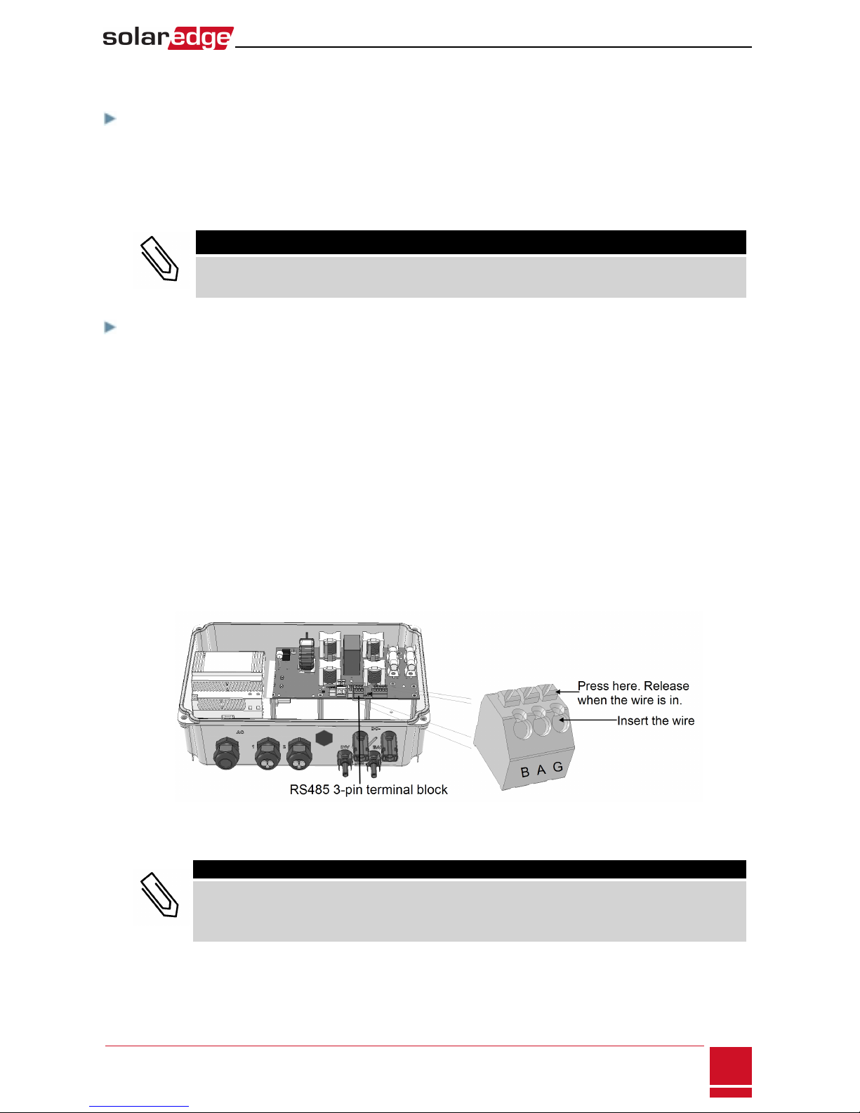
1. ConnectoneendtotheRS485terminalblockmarked"RS485toInv."intheStorEdgeInterface:
a. Opengland#2.
b. Removethesealfromoneoftheopeningsandinsertthewirethroughtheopening.
c. Connectthewireendsinthe A, BandGpins(useatwistedpairforAandB):Useaflatblade
screwdrivertopresstheprotrusionatthetopoftheterminalblockandopentheconnection
hole;insertthewireandreleasetospringbackandclampthewire.
YoucanuseanycolorwireforeachoftheA,BandGconnections,aslongasthesamecolorwire
isusedforbothApins(inverterandStorEdgeInterface,thesamecolorforbothBpinsandthe
samecolorforbothGpins.
Figure 13: RS485 connector in the StorEdge Interface
2. Connecttheotherendofthecommunicationcabletotheinvertercommunicationboard:
NOTE
The wires from the meter and from the StorEdge Interface are inserted into the same pins in the
inverter RS485 terminal block. Make sure that the meter wires are not disconnected when
inserting the Interface wires.
a. Opentheinvertercoverasdescribedinitsmanual.
Chapter 3: StorEdge Interface Installation
SolarEdge-StorEdge Installation Guide MAN-01-00249-1.2
11
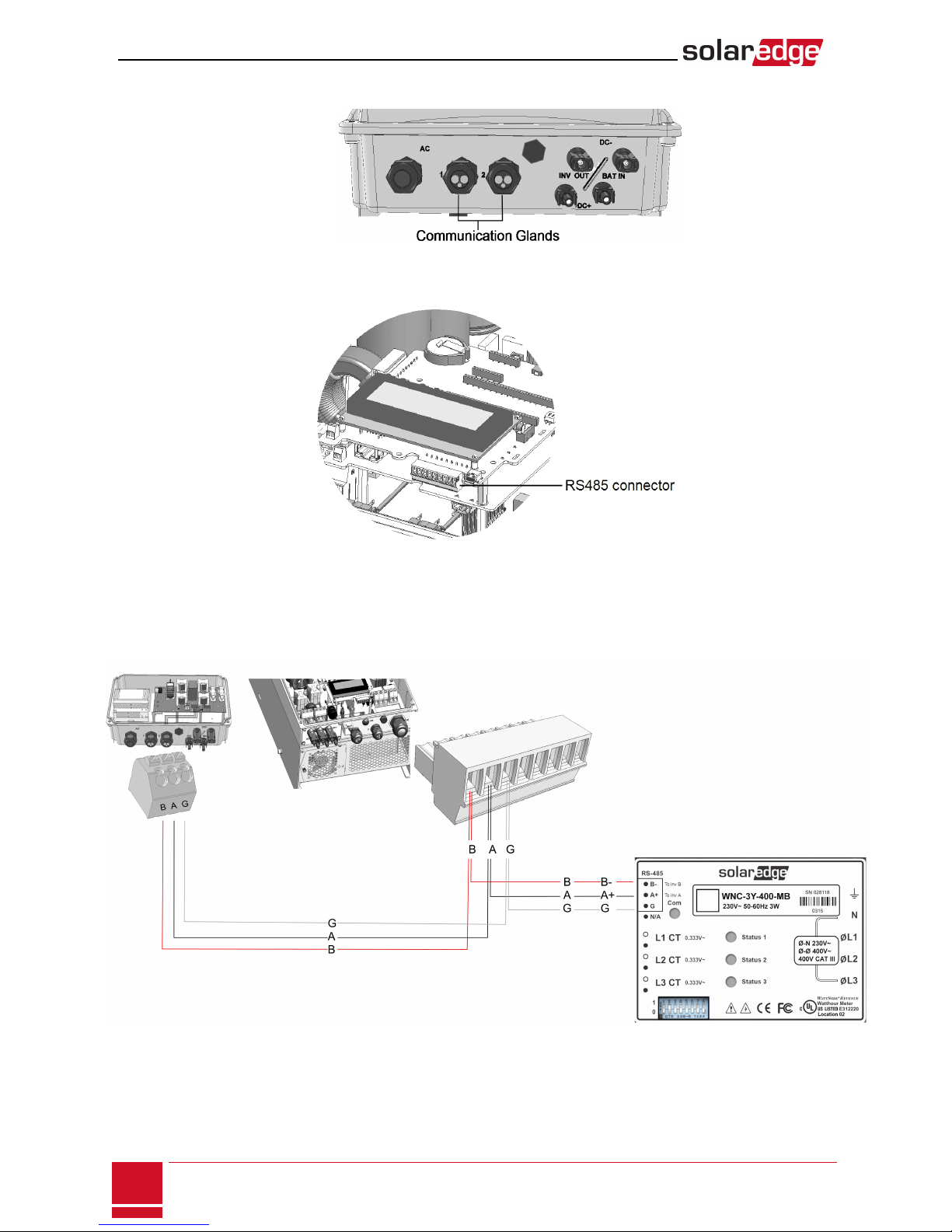
b. Removethesealfromoneoftheopeningsinthecommunicationglandandinsertthewire
throughtheopening.
Figure 14: Communication glands
c. Pulloutthe9-pinRS485terminalblockconnector,asshownbelow:
Figure 15: Inverter RS485 terminal block
d. LoosenthescrewsofpinsA(+),B(-),andGontheleftoftheRS485terminalblock.
e. InsertthewireendsintotheG, AandBpins.
3. Checkthatthewiresarefullyinsertedandcannotbepulledouteasily.
Figure 16: Connections to the inverter (and meter)
SolarEdge-StorEdge Installation Guide MAN-01-00249-1.2
12
Connecting the StorEdge Interface to the Inverter

Connecting the StorEdge Interface to AC
NOTE
The AC is used for auxiliary power only and does not carry high power.
Useathree-wirecablewithacrosssectionof1-2mm2.
To connect to AC:
1. TurnOFFtheACpowersourcetobeconnectedtotheinterface.
2. RemovetheinterfaceACsealinggland.
3. Stripoff5/16"(8mm)oftheACcableinsulationandexposetwolinewiresandonegroundingwire.
4. InserttwowireendsintotheACterminals(L,N).Fastenthescrewswithatorqueof0.67N*m/0.5
lb*ft.
Figure 17: AC and grounding connections
5. Connectthegroundingwiretothegroundingterminal(bus-bar).Youcanusethebus-bartoconnect
thebatterygroundingcable.
Figure 18: StorEdge Interface grounding
Chapter 3: StorEdge Interface Installation
SolarEdge-StorEdge Installation Guide MAN-01-00249-1.2
13

Connecting the StorEdge Interface to the Battery Pack
Beforeinstallingthebatterypackaccordingtotheinstructionsprovidedbythebatterymanufacturer,
connectthebatterytotheStorEdgeInterfaceasdescribedinthissection.
Followtheseguidelines:
lForeasyaccesstobatteryconnectors,itisrecommendedtoconnectthecablestothebatteryand
tosetallthebatteryDIPswitchestotheircorrectpositionswhilethebatteryisstillontheground.
Thefollowingprocedureisrecommended:
a. Connectallthewirestothebatteryconnectionpanel
b. Mountthebattery
c. ConnecttotheStorEdgeInterface.
lMeasurethenecessarylengthbetweentheStorEdgeInterfaceandthebatteryforallcables.
lTieandwrapthecablestoavoidpullingthemoutduringmounting.
lBesuretoadheretoallsafetycautionsandinformationinthebatterydocumentation.
SolarEdge-StorEdge Installation Guide MAN-01-00249-1.2
14
Connecting the StorEdge Interface to the Battery Pack

To connect the battery pack and the interface:
1. Preparecablesandconnectasdescribedinthefollowingtable:
Recommended
cable type (min-max
cross section)
StorEdge Interface
connection
Tesla battery
connection
Connection
method
DC
One pair of PV DC cables
with a cross section of 6
(4-6)mm2, 600V
insulated, with MC4
connectors at one end.
BAT DC + DC +
BAT DC - DC -
12V thermal power input
2-wire shielded twisted
pair cable with cross
section of 1.5 (0.1-2.5)
mm², 600V insulated
Battery Thermal V- (black) THERMAL -
Push the lever to open
the connection, insert
the wire and release
the lever when the wire
is clamped.
Battery Thermal V+ (red) THERMAL +
Control and monitoring
5-wire shielded twisted
pair cable with a cross
section of 0.2 (0.2-1.5)
mm².
A CAT5 600V insulated
cable can also be used.
5-pin communication terminal
block:
communication port 1
(located closer to the
DIP switches): Press the protrusion at
the top of the terminal
block to open the
connection hole, insert
the wire and release to
spring back and clamp
the wire.
En (Enable) ENABLE
V+ LOGIC +
G (RS485) LOGIC -
B (RS485)1COM LO1
A (RS485) COM HI
Modbus DIP switch
setting:
oS2, S6: Left
oS1, S5: DOWN
oS3, S4: UP
ID DIP switch setting:
All (1,2,3) to the right (0
position)
Refer to Figure 19 and
Figure 20
Battery grounding
Optionally connect to the second
grounding spring terminal (see
figure Figure 17)
Grounding lug
2. Closetheinterfacecover:Attachthecoverandsecureitbytighteningthefourscrewswithatorque
of1.2N*m/0.9ft.*lb.
1Must be twisted pair
Chapter 3: StorEdge Interface Installation
SolarEdge-StorEdge Installation Guide MAN-01-00249-1.2
15

Figure 19: StorEdge Interface Connections
Connecting the StorEdge Interface to the Battery Pack
SolarEdge-StorEdge Installation Guide MAN-01-00249-1.2
16

Figure 20: Battery DIP switches
SolarEdge-StorEdge Installation Guide MAN-01-00249-1.2
17
Connecting the StorEdge Interface to the Battery Pack

Chapter 4: System Configuration
ThischapterdescribeshowtoconfigureyourStorEdgesystembysettingupthecommunication
betweenthesystemcomponentsandsettinguptherequiredapplication.TousetheStorEdge
applications,theinvertercommunicationboardfirmware(CPU)versionmustbe3.xxxxandlater.Ifyou
haveaninverterwithCPUversion2.xxxx,contactSolarEdgesupport.
Upgrading the Inverter Firmware Version
UpgradetheinverterfirmwareusingthecardsuppliedwiththeStorEdgeInterface.
To upgrade the inverter firmware:
1. Makesuretheinverterhasbeenactivatedusingthecardsuppliedwiththeinverter.
2. Ifapplicable-makesuretheON/OFFswitchoftheStorEdgeInterfaceisOFF.
3. MakesuretheON/OFFswitchoftheinverterisOFF.
4. Insertthecardintothecommunicationboardslotmarked“CARD”.
Figure 21: Inserting the upgrade card
5. TurnontheACtotheStorEdgeInterface.
6. TurnontheACtotheinverter.
WARNING!
ELECTRICAL SHOCK HAZARD. Do not touch uninsulated wires when the inverter cover is
removed.
7. EntertheinverterSetupmode:PresstheinternalEnterbuttonfor5-10secondsandrelease.Enter
thepassword12312312.
8. SelectMaintenanceèSW Upgrade – SD Card.TheLCDshows:Running Script...èDone!
IftheLCDshows:Script error,contactSolarEdgeSupport.
SolarEdge-StorEdge Installation Guide MAN-01-00249-1.2
18
Chapter 4: System Configuration

Configuring the RS485 Bus for Battery and Meter
Connection
ThissectiondescribeshowtosetuptheRS485communicationbetweentheinverter,meter,StorEdge
Interface,andbattery.
To configure the RS485 bus:
1. SelectCommunicationè RS485-1 Conf è Device Type è Multi Devices.Alistofdevicesis
displayed.
D e v i c e T y p e < M L T >
M e t e r 1 < - - - >
M e t e r 2 < - - - >
B a t t e r y 1 < - - - >
2. SelectMeter 2.Themeterconfigurationscreenisdisplayed:
D e v i c e T y p e < M T R >
P r o t o c o l < W N >
D e v i c e I D < 2 >
C T R a t i n g < 0 >
M e t e r F u n c . < N o n e >
3. Configurethemeter:
a. SelectDevice Type è Revenue Meter
b. SelectProtocol è WattNode
c. VerifythatDevice IDissetto 2.
d. SettheCTvaluethatappearsontheCTlabel: CT Rating è <xxxxA>.
IfCTresetsto0,checkthecommunicationasdescibedinstepbbelow.
e. ForameterinstalledstthegridconnectionpointselectMeter Func.è Export+Import.
Export+Import
E x p o r t
Consumption
P r o d u c t i o n
I m p o r t
N o n e
TheselectedoptionisdisplayedintheRS485Confscreenas<E+I>.
4. SelectBattery 1.Thebatteryconfigurationscreenisdisplayed:
D e v i c e T y p e < B A T >
P r o t o c o l < T 7 4 >
D e v i c e I D < 2 4 >
B a t t e r y I n f o < >
5. SelectDevice Type èBattery Pack.
Chapter 4: System Configuration
SolarEdge-StorEdge Installation Guide MAN-01-00249-1.2
19
Other manuals for storedge
6
Table of contents
Other SolarEdge Recording Equipment manuals


