Kongsberg Simrad GI51 User manual

Note!
Simrad AS makes every effort to ensure that the information contained within this
document is correct. However, our equipment is continuously being improved and
updated, so we cannot assume liability for any errors which may occur.
Warning!
The equipment to which this manual applies must only be used for the purpose for which
it was designed. Improper use or maintenance may cause damage to the equipment or
injury to personnel. The user must be familiar with the contents of the appropriate
manuals before attempting to operate or work on the equipment.
Simrad AS disclaims any responsibility for damage or injury caused by improper
installation, use or maintenance of the equipment.
Copyright
© 2004 Simrad AS
The information contained within this document remains the sole property of Simrad AS.
No part of this document may be copied or reproduced in any form or by any means, and
the information contained within is not to be communicated to a third party, without the
prior written consent of Simrad AS.
Busse-Yachtshop.de [email protected]

INSTALLATION MANUAL
20221594 / B i
Installation Manual
GI51 Gyro Interface
This manual is to be used when installing the Simrad GI51
Gyro Interface.
Busse-Yachtshop.de [email protected]

Simrad GI51 Gyro Interface
ii 20221594 / B
Document revisions
Rev Date Written by Checked by Approved by
A 18.02.04 / / /
B 30.04.04 / /
Document history
Rev. A First issue
Rev. B Updated to include new functions. Corrections/updates added to other
pages .
To assist us in making improvements to this manual, we would welcome comments and
constructive criticism. Please send all such - in writing to:
Simrad Egersund AS
Nyåskaien
P.O. Box 55
N-4379 Egersund, Norway
or by e-mail to:
simrad.documentation@simrad.com
Busse-Yachtshop.de [email protected]

INSTALLATION MANUAL
20221594 / B iii
Contents
1INTRODUCTION ................................................................5
2INSTALLATION..................................................................5
2.1 Mechanical installation ........................................................5
2.2 Cabling .............................................................................5
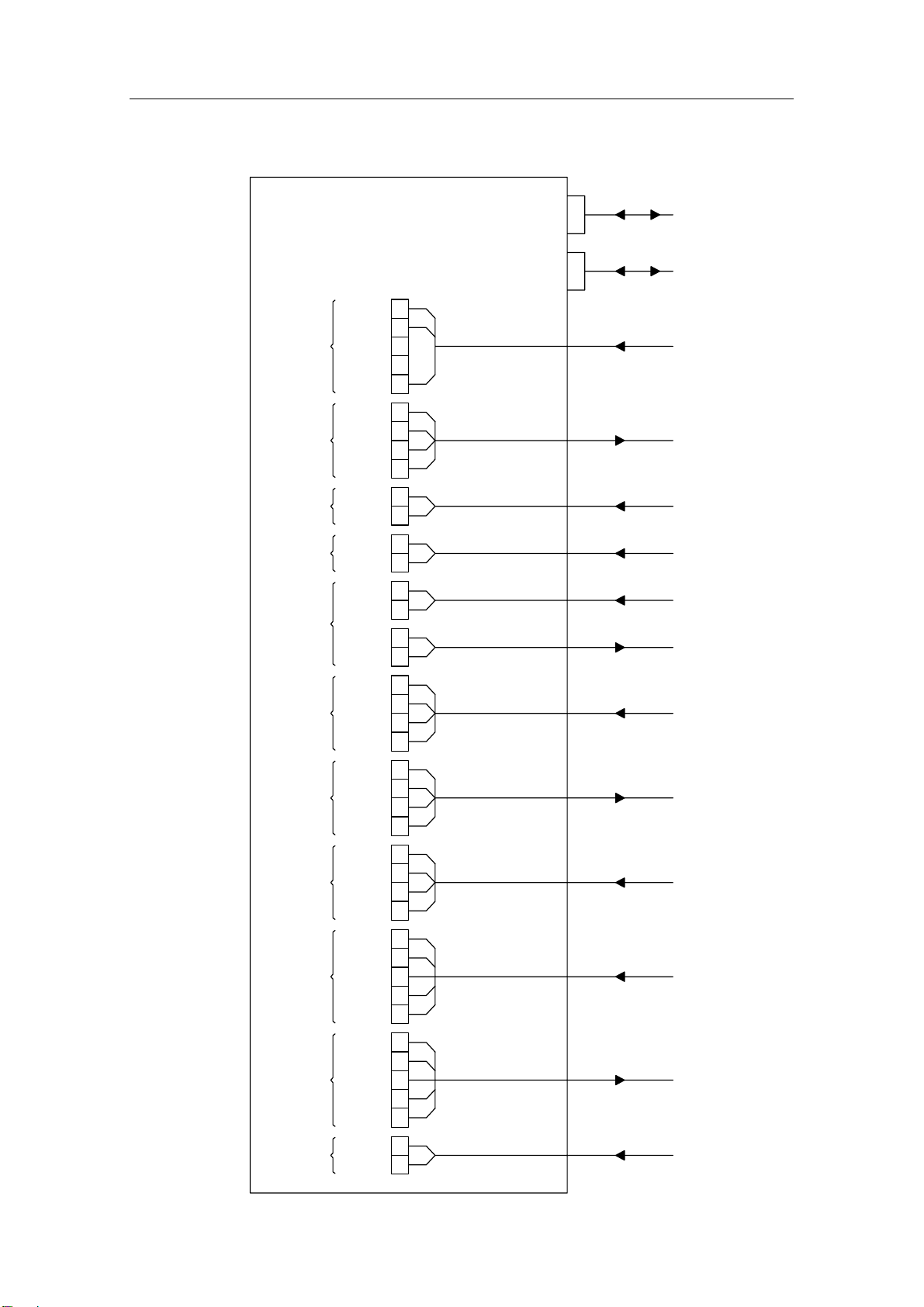
GI51 Block diagram .......................................................6
2.3 Dip switch settings..............................................................7
2.4 Interface setup procedure....................................................8
2.5 Offset adjustment...............................................................8
2.6 Calibration.........................................................................9
2.7 Initial heading and heading change test ............................... 10
2.8 S9 Steering lever.............................................................. 11
3GI51 PCB ........................................................................12
3.1 Component location .......................................................... 12
3.2 Terminal description ......................................................... 13
TB1, Power................................................................. 13
TB2, Sin/Cos Out ........................................................ 13
TB3, Synchro In .......................................................... 13
TB4, NFU ................................................................... 13
TB5, Step Out............................................................. 13
TB6, Step In............................................................... 14
TB7 and TB8, NMEA..................................................... 14
TB9, RGC proprietary................................................... 14
TB10, LOG ................................................................. 14
TB11, Radar ............................................................... 14
TB12, Selector ............................................................ 15
4PENDULUM FUNCTION KEY (OPTION).............................16
5TROUBLE SHOOTING .......................................................17
5.1 LED indicators.................................................................. 18
6SPARE PARTS ..................................................................19
7TECHNICAL SPECIFICATIONS .........................................20
7.1 Hardware ........................................................................ 20
7.2 Supply ............................................................................ 20
Busse-Yachtshop.de [email protected]

Simrad GI51 Gyro Interface
iv 20221594 / B
7.3 Interface ......................................................................... 21
Input......................................................................... 21
Output....................................................................... 21
Other serial output/input .............................................. 22
Busse-Yachtshop.de [email protected]

INSTALLATION MANUAL
20221594 / B 5
1INTRODUCTION
The GI51 is a multi purpose interface unit designed for
converting various input signals to Robnet, sin/cos, stepper
signal, NMEA 0183, and Clock Data output signals. Refer
TECHNICAL SPECIFICATIONS, page 20.
The GI51 may be used both in a Robnet system and as a stand-
alone unit.
Note!
If GI51 is used together with the AP20 or AP35/16, it must be
configured as stand alone.
The unit has a pendulum ferry feature that will change the
heading output by 180° on command when the unit is connected
to Robnet. If not connected to Robnet, an optional GI51 function
key is required to activate the pendulum ferry function. Refer
PENDULUM FUNCTION KEY (Option), page 16.
2INSTALLATION
2.1 Mechanical installation
The GI51 should be mounted with regard to the environmental
protection and temperature range of the unit, and should not be
installed in area exposed for heavy vibrations.
Make allowances for working area around the unit when routing
or removing the cables.
Fasten the GI51 to the bulkhead. Refer mechanical drawing,
page 20.
2.2 Cabling
All cable conductors are terminated in screw terminals on the
GI51 pcb.
Connect equipment according to the block diagram on page 6,
and to Terminal description, page 13 onwards.
To make a good ground connection, strip about 1 cm (0.4”) off
the cable’s insulation and pull the screen backwards to cover the
insulation. Position the straps as shown in the figure. Tighten
well to make sure the screen makes good contact.
This will also avoid vibration causing the cables to loose
connection.
Note!
Be careful not to drop screen cuts over the components!
Busse-Yachtshop.de [email protected]

Simrad GI51 Gyro Interface
620221594 / B
GI51 Block diagram
SELECTOR
RADAR
LOG
RGC
NMEA
STEP IN
STEP OUT
NFU
SYNCHRO
SIN/COS
PWR
SEL.2
SEL.3
SEL.4
SEL.1
+12V
CLK L
CLK H
DATA L
DATA H
PULSE
+12V
RX-
RX+
TX-
TX+
RX-
RX+
COM
STEP 3
STEP 2
STEP 1
STEP 3
STEP 1
STEP 2
COM
ENABLE
PORT
STBD
+12V
S3
S2
S1
R2
R1
COS
SIN
APGND
V/2
-
AP+
+
TB12
TB11
TB10
TB9
TB8
TB7
TB6
TB5
TB4
TB3
TB2
TB1
ROBNET CONNECTORS
J2
J1
GI51 PCB
Busse-Yachtshop.de [email protected]

INSTALLATION MANUAL
20221594 / B 7
2.3 Dip switch settings
The following dip-switches have to be set correctly:
-SW1-1 and SW1-2 determine the gearing ratio for synchro
input. For 1:1 synchro or if synchro is not used, both are
set to OFF
-SW1-3 determines the format of the clk/data heading
signal to the radar. If the unit is powered by the Robnet,
the format is set from the autopilot control unit. Hence the
switch is not used and the settings for the switch is
irrelevant.
-SW1-4 can be used for test and trouble shooting (ref. page
17). When the switch is set to ON, the heading at all
outputs will jump in circles in a sequence of 45° each 10
sec.
-SW2-1 set to OFF gives NMEA and Robnet speed output
from the pulse log input. If set to ON, speed will be taken
from the longitudinal water speed field of VBW
(1.priority) or VHW (2.priority) of the NMEA input.
-SW2-2 is used to determine the internal gain for high
voltage 50-100V ref. (L/L or low voltage, 26V ref., 11.8V
L/L synchros. OFF sets the gain for high voltage level
(others), ON sets the gain for low voltage, 26V/11.8 V
L/L.
All switches are factory set to OFF.
For location of the dip-switches, refer to Component location,
page 12.
Position/Function
Switch no.
OFF ON
SW1-1 Synchro 1:1 Synchro 90:1
SW1-2 Synchro 1:1 Synchro 360:1
SW1-3 Simrad clk/data
(Stand-alone)
Furuno clk/data
(Stand-alone)
SW1
1234
SW1-4 Normal Heading test
Position/Function
Switch no.
OFF ON
SW2-1 NMEA log Pulse log
SW2-2 Others 26V Ref., 11.8V L/L
SW2-3 NC NC
2143
SW2
SW2-4 NC NC
Busse-Yachtshop.de [email protected]

Simrad GI51 Gyro Interface
820221594 / B
2.4 Interface setup procedure
When a compass is connected to the GI51 via Robnet, it is
required to configure the compass in the autopilot Interface
Setup Menu.
Note!
For AP50 the gyro type has to be selected under the “GI-menu”
shown in the Interface menu.
The procedure to access the Interface Setup Menu is detailed in
the respective autopilot manual.
If more than one compass is connected to a GI51, operating as
“stand alone”, the input compass will be selected at power on in
the following order: Synchro (1.priority) →Step →RGC →
NMEA.
2.5 Offset adjustment
Without Robnet connection to GI51, heading offset adjustment
is required after power on. This can be done either by a
proprietary NMEA data (ref. page 22) or by an external switch
connected between the SEL 3 and +12V.
+12V
SEL.1
SEL.3
SEL.2
SEL.4
SELECTOR
TB12
The switch must be a potentional free pulse type. When pressing
and holding the switch, the heading will increase or decrease,
depending of last direction control.
The heading will increase in a slow rate for the first 2 degrees,
but change to high rate for as long as the switch is depressed. By
making a quick double press and keep the last press, the
direction is reversed and started with low rate. Single presses on
the switch changes the heading by one tenth of a degree.
The switch should be mounted in a location for convenient
operation.
Note!
Make sure that the switch is mounted on a protected area to
avoid unintended operation that will give large heading changes!
Busse-Yachtshop.de [email protected]

INSTALLATION MANUAL
20221594 / B 9
2.6 Calibration
For other types of synchro voltages, it is recommended to
perform a heading calibration to obtain the maximum heading
accuracy. Calibration can be performed by either turning the
vessel, slew the compass or rotating the synchro. As the internal
gain is related to synchro voltage, dip switch SW2-2 is used to
select “high reference voltage” (50-100V) or “lo reference
voltage” (26V). See page 7. Note that no calibration is required
for geared synchros. The calibration may be omitted if reduced
accuracy (1-2°) can be accepted.
When connected to a Simrad autopilot, the calibration is started
from the autopilot (Robnet). It will be confirmed and read in the
autopilot (confirmed or failed). The GI51 is factory calibrated
for Simrad RGC50/10/11 type gyro with 1:1 synchro. Note that
RGC11 and 1:1 synchro is NOT standard but optional. See
autopilot manual for more info.
When compasses are connected to GI51 as “stand alone” and
calibration may become difficult or impractical due to vessel
size, port condition etc, a separate dip switch (SW2-2) function
is included to avoid the calibration. See Dip switch settings,
page 7.
Note!
For a 1:1 synchro, minor errors may be present, therefore a
calibration when the vessel is out at the open sea is
recommended. Use the following procedure:
1Connect the power to the GI51.
2Make some 360 degrees turns within 10 minutes from
power-on. Normally the compass becomes calibrated
within passing north three times. The heading sensor
should now be calibrated. The green CPU Running LED
changes from flashing to constant on for about 7 seconds,
indicating that the calibration is accepted.
Note!
If you have access to a computer with the appropriate NMEA
interface, you can perform a calibration procedure using the
proprietary sentences as listed in page 22.
Busse-Yachtshop.de [email protected]

Simrad GI51 Gyro Interface
10 20221594 / B
2.7 Initial heading and heading change test
This section describes how to verify that the heading read-out
from the GI51 is following the correct direction of change along
with the gyro. In some cases, it may be encountered that the
autopilot heading read-out is different from the gyro heading.
Two possibilities of error may exist:
1Compass read-out on the autopilot is different from the
gyro card read-out, but the heading difference is a constant
on all headings. This condition can be correct by simply
dialing in the correct heading value from the Seatrial
Menu item called Compass Offset, presented directly after
the Compass Calibration menu item, from the Seatrial
Settings Menu.
2If there is a difference of approximately 120° or 240°
between the master compass heading and the
autopilot/repeaters when the NMEA signal is used, S1 - S2
- S3 and R1 - R2 connections between the master compass
and GI51 need to be changed. Use one of the alternatives
listed below.
If the compass can be slewed (heading changed) use the
procedure in Alternative 1. If it is not possible to slew the
compass, Alternative 2 should be used:
Alternative 1
-Disconnect S1 - S2 - S3 from GI51 TB3.
-Slew the master compass to 000°.
-Use a multimeter and measure the AC voltage (0 - 90V
range) between S1 - S2 - S3 on the disconnected wires.
-Locate the two phases where the voltage is approx. 0 volt.
These are the S1 and S3 lines. Connect S1 - S3 – S2
accordingly.
-If the change in heading is in the same direction for the
master compass and the repeaters, but a constant 180°
offset is present, the R1 and R2 lines need to be
interchanged. (This does not reverse the rotation).
-Rotate the master compass to make the heading increase.
If the repeater heading decreases, the S1 and S3 lines need
to be interchanged.
Alternative 2
-The sequence of connections S1-S2-S3, R1 and R2 may be
wrong. Reversing two phases will change the direction.
Swapping S1 to S2, S2 to S3 and S3 to S1 will change the
response by 120° or 240°. Interchanging R1-R2 will
change the heading by 180°.
Busse-Yachtshop.de [email protected]

INSTALLATION MANUAL
20221594 / B 11
If only a constant small error should occur, loosen the fixing
screws for the synchro transmitter and adjust by moving the
synchro transmitter for correct heading output from the GI51.
2.8 S9 Steering lever
The S9 Steering Lever can be added to an autopilot system to
provide remote non-follow up steering capability. The S9 is
designed to be mounted in weather exposed locations. If it is
installed in such location, it is recommended to insure that the
cable entry glands are properly tightened. In addition silicone
sealant should be added around cable to ensure water protection.
As the mode selection by the Enable signal is based on a pulse,
it is recommended that only one S9 lever is used. This because
the mode selection switch is fixed levels, not pulsed. If several
NFU levers are required, the S35 lever is recommended.
Busse-Yachtshop.de [email protected]

Simrad GI51 Gyro Interface
12 20221594 / B
3GI51 PCB
3.1 Component location
Step 3
STEP INSELECTOR
SEL.2
SEL.4
SEL.3
LOG
+12V
RADAR
Clk H
+12V
SEL.1
Clk L
Data H
Data L
Pulse
NMEA
RGC
TX+
RX+
RX-
TX-
RX+
RX-
Com
CPU
RUNNING
OK
POWER
Port
STEP OUT
Step 3
Step 1
Step 2
Com
Step 1
Step 2
Enable
NFU SYNCHRO
+12V
Stbd
S3
S2
S1
R2
R1
PWR
SIN/COS
V/2
Cos
APGND
Sin
AP+
-
+
J1
J2
CONNECTORS
SW2
SW1
PLUG
FUNCTION KEY
PROGRAM /
FAULT
SYNCHRO
SPEED LOG
(PULSE)
CLK
RADAR
RGC RX
RX
NMEA
TX
NMEA
IN
STEP
STEP
OUT
LED
F1
Busse-Yachtshop.de [email protected]

INSTALLATION MANUAL
20221594 / B 13
3.2 Terminal description
TB1, Power
PWR
-
+
Used for power connection when GI51 is not powered by
Robnet.
When power is connected to TB1 in a Robnet system, GI51 will
continue to output gyro heading even if the autopilot is turned
OFF.
TB2, Sin/Cos Out
V/2
Cos
APGND
Sin
AP+
SIN/COS
Used for heading output to certain models of Simrad autopilots
(AP200 series, AP45, AP9).
TB3, Synchro In
R2
SYNCHRO
S2
S3
S1
R1
Used for connecting gyro compasses with synchro output. Refer
Dip switch settings, page 7for signal specification.
TB4, NFU
Enable
Port
Stbd
+12V
NFU
Used for connecting a remote Non Follow Up lever. Rudder
command or course change will be sent to the autopilot via
Robnet.
Simrad S9 lever also enables remote auto/NFU mode switching.
TB5, Step Out
Step 2
Step 3
Step 1
STEP OUT
Com
Used for operating heading repeaters with step input.
Note!
Step signals only for electronic interface, not for step motors!
See TECHNICAL SPECIFICATIONS, page 20.
Busse-Yachtshop.de [email protected]

Simrad GI51 Gyro Interface
14 20221594 / B
TB6, Step In
STEP IN
Com
Step 3
Step 2
Step 1
Used when connecting a gyro compass with stepper output.
TB7 and TB8, NMEA
NMEA
TX+
TX-
RX+
RX-
NMEA signals from compass or speed log with serial output
should be connected to RX- and RX+. Refer Dip switch settings
for speed, page 7.
Output heading from active steering compass and speed from log
in the GI51 is available on TX- and TX+.
TB9, RGC proprietary
RX-
RX+
RGC
Used for reading serial data (9600 baud) from gyro compass
(RGC11, RGC12).
TB10, LOG
Pulse
+12V
LOG
Used for connecting speed log with 200p/NM. Refer Dip switch
settings, page 7.
TB11, Radar
Data L
RADAR
Clk L
Clk H
Data H
Data and Clock output signal to Radar.
Simrad or Furuno format is selected via Robnet, or set by dip
switch SW1 if GI51 not is connected to Robnet. Refer Dip
switch settings, page 7.
Busse-Yachtshop.de [email protected]

INSTALLATION MANUAL
20221594 / B 15
TB12, Selector
SEL.4
SEL.2
SEL.3
SEL.1
SELECTOR
+12V
The selector lines option on TB12 are used both for heading
offset adjustment and for the optional pendulum function key as
described below.
Offset heading adjustment
Offset of initial heading will be required when a step or geared
synchro is connected in a stand-alone system. The function is
obtained by connecting a pulse switch between TB12, +12V and
SEL 3. When pressing and holding the switch, the heading will
increase or decrease, depending of last direction control.
The heading will increase in a slow rate for the first 3 degrees,
but change to high rate for as long as the switch is depressed. By
making a quick double press and keep the last press, the
direction is reversed and started with low rate. Single presses on
the switch changes the heading by one tenth of a degree.
Pendulum ferry feature
Based on reading an external potential free switch connected to
this terminal, GI51 will change the heading output 180° on
command for both the steering compass and monitor compass (if
installed).
The switch is connected between +12V and SEL.4.
Busse-Yachtshop.de [email protected]

Simrad GI51 Gyro Interface
16 20221594 / B
4PENDULUM FUNCTION KEY (Option)
If GI51 not is connected to Robnet, an optional Pendulum
function key (part no. 20213815) has to be installed to activate
the pendulum function. When this key is installed, GI51 will
change the heading output by 180° based on signal from a
potential free closing contact between TB12, Sel 4 and +12V on
the GI51 pcb. Refer page 15.
A LED is visible through the whole on the key. The LED has
the following indication:
-No light: true heading output
-Intermediate flashing: heading is changed 180°
Use the following procedure to install the pendulum key:
1. Remove power from the GI51 unit.
2. Open the unit and locate P1 on the pcb. Refer Component
location, page 12.
Pendulum
function key
P1
3. Carefully insert the pendulum function key into P1. Observe
the guiding slot as indicated on the figure.
4. Press carefully until the key is properly inserted.
Busse-Yachtshop.de [email protected]

INSTALLATION MANUAL
20221594 / B 17
5TROUBLE SHOOTING
For location of the LEDs, refer to Component location, page 12.
SYMPTOM CORRECTIVE ACTION
The unit is
inoperative.
1. Check that the POWER OK LED
is lit.
2. Check that the CPU RUNNING
LED is alternating at 1Hz.
No compass output. 1. Check LED indicator(s) for all
heading outputs. Note that
whenever the selected input
compass is unreliable (signal
missing, invalid flag received etc),
GI51 will:
-Turn on all 3 LEDs for step out
-Set sin/cos to zero
-Stop clk/data output
-Transmit invalid flag and empty
heading field in NMEA output
2. If all output indicators operate ok,
check cabling for missing output
signal.
3. If output indicators show missing
or invalid input (all 3 LEDs for
step out is lit etc), check LED(s)
for selected input compass.
4. If LED(s) for selected input
compass operate ok, check
compass status.
5. If LED(s) for selected input
compass indicate missing signal,
check input cabling.
6. For synchro input, check the
Synchro Fault LED which will be
lit if the reference or any of the
phases are missing. Also check
correct setting of DIP switches (no
output if both SW1-1 and SW1-2
are ON).
Busse-Yachtshop.de [email protected]

Simrad GI51 Gyro Interface
18 20221594 / B
SYMPTOM CORRECTIVE ACTION
No speed output 1. Check LED indicator for Speed
Log input or NMEA RX
(depending upon which signal that
is selected by DIP switch SW2.1).
2. Check LED for NMEA input.
3. If input signal is missing, check
cabling or status of speed log.
4. If input signal is ok, check cabling
for output signal
Note!
If pulses from the speed log fail to appear, the speed will
decrease towards zero during the next half minute before the
speed output is stopped.
5.1 LED indicators
Several LED indicators are used to indicate correct status for
power and input/output signals.
For location of the LEDs, refer to Component location, page 12.
LED NO. COLOUR INDICATION
D1 Green
CPU running indicator. Flashes with apr. 1Hz when the
processor is running.
D103 Green
Power polarity indication. Green light when polarity is
correct.
D400
D401
D401
Green Step out indicators. Flashes with Step Out signal.
D603 Green NMEA In indicator. Flashes with NMEA In signal.
D602 Green NMEA Out indicator. Flashes with NMEA Out signal.
D1000
D1001
D1002
Green Step In indicators. Flashes with Step In signal.
D1301 Green
RGC proprietary indicator. Flashes with RGC proprietary
signal.
D1600 Red
Synchro fault indicator. Will be lit if any signal is lost or if
no synchro is connected.
Busse-Yachtshop.de [email protected]
Table of contents
Other Kongsberg Recording Equipment manuals