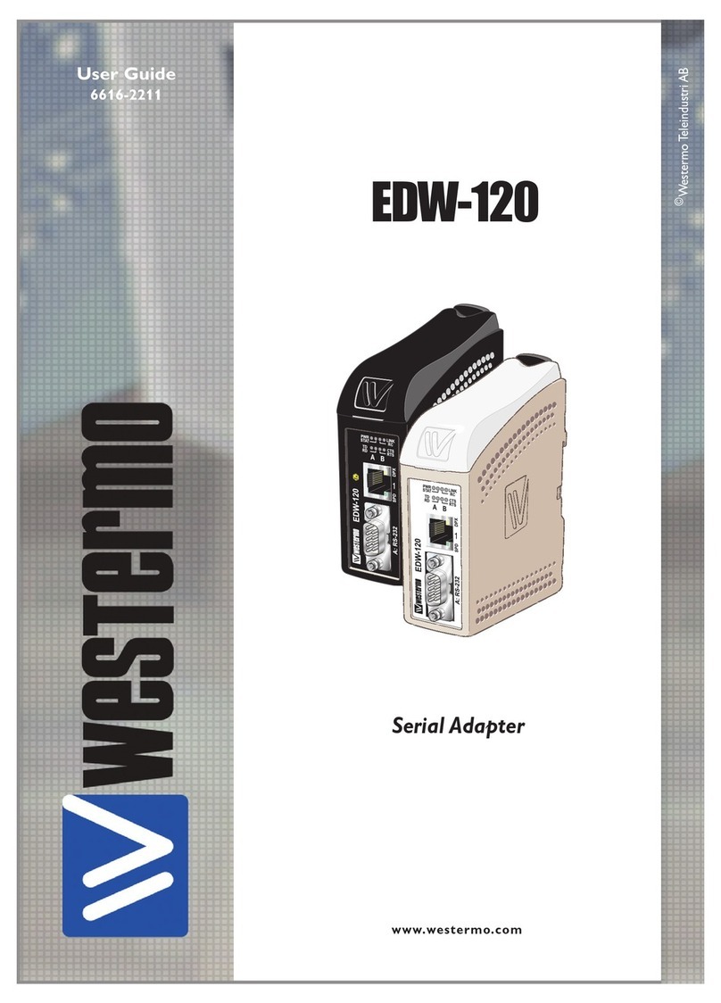
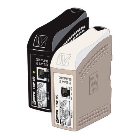
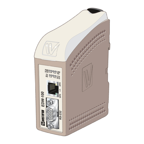
Westermo ED-10 TCP User manual

Industrial Ethernet adapter
– Serial Server (TCP)
INSTALLATION MANUAL
6609-2211
www.westermo.com
E -10
TCP
©Westermo Teleindustri AB • 2001 • REV. B
Galvanic
Isolation Transient
Protection Balanced
Transmission CE
Approved


36609-2211
Contents
1. Introduction .......................................................................................................................................................................... 4–5
2. Safety ............................................................................................................................................................................................................ 5
3. Specification ......................................................................................................................................................................... 6–7
4. Maintenance ................................................................................................................................................................................ 5
5. Installation ....................................................................................................................................................................................... 8
5.1 Mounting / Removal ............................................................................................................................... 8
5.2 Connections ............................................................................................................................................ 9–10
5.2.1 RS-422/485 general advice ............................................................................... 11–12
5.3 Configuration ............................................................................................................................................... 13
5.3.1 IP switch settings ...................................................................................................... 13–14
5.3.2 LE 's ............................................................................................................................................................ 15
6. Functional description ......................................................................................................................... 17–18
7. Configuration ........................................................................................................................................................................ 19
7.1 Configuration by E -Tool ............................................................................................. 19–21
7.2 Configuration by terminal ............................................................................................ 22–24
7.2.1. Local configuration .............................................................................................................. 24
7.2.2. Remote configuration ...................................................................................................... 24
7.3 Configurable parameters ............................................................................................... 25–26
7.3.1. Serial interface ........................................................................................................................... 27
7.3.2. Packing algorithm .................................................................................................................. 28
7.3.3. Network interface ................................................................................................................. 29
7.3.4. Mode .......................................................................................................................................................... 30
7.3.5. MAC address ................................................................................................................................. 30
7. Application examples ....................................................................................................................................... 31

46609-2211
1. Introduction
The ED-10 TCP is an Industrial Ethernet Adapter a ting as a serial server. The type of
serial interfa e is sele table between RS-232 and RS-422/485. The Ethernet interfa e is
10BASE-T and TCP/IP Proto ols are implemented for network ommuni ation.
The ED-10 TCP provides a remote serial interfa e for a omputer onne ted through a
TCP/IP network.
To omplete the onne tion to the ED-10 TCP additional software need to be used in
the omputer. Different solutions are possible, e.g.:
1. Telnet to the ED-10 TCP.
All keystrokes are trans-
ferred to the remote seri-
al interfa e.
Any hara ters re eived at
the remote serial interfa e
are transferred to the
omputer s reen.
2. A COM port redire tor
software an be used to
reate up to 256 virtual
COM ports.
This software will redire t
data, originally sent to a
lo al COM port, to the remote serial inter-
fa e of the ED-10 TCP. No hange of om-
puter appli ation software is then ne essary.
3. Customer written software an be used to
dire tly a ess the network interfa e (so ket
ompliant) of the ED-10 TCP.
A sample written in C++ an be found on
the CD ”\Software\Sample\sample.zip”
Network interface
Application software
Solution 2
Data to / from COM3
Data to / from COM4
Data to / from COM5
Data to / from COM256
COM port
redirector software
543
2
1
Network
ED-10TCP
COM3
543
2
1
ED-10TCP
COM4
543
2
1
ED-10TCP
COM256
543
2
1
ED-10TCP
COM5
ED-10 TCP Virtual COM ports onne tion

56609-2211
The ED-10 TCP is ideal for use in the industrial environment.
It is housed in the Westermo DIN rail box and has a wide range power input, isolated
interfa es and enhan ed surge/transient prote tion.
The ED-10 TCP is approved for Industrial EMC Immunity and Emission .
The ED-10 TCP uses the TCP/IP Internet Proto ol Suit (TCP/IP) to transfer data over
the network.
TCP/IP is a set of proto ols that enables ommuni ation a ross lo al and wide area net-
works and in ludes proto ols su h as TCP, UDP, IP , ARP, RARP, ICMP. Although not
all these proto ols are needed for a network data transfer.
The ED-10 TCP uses TCP for remote onfiguration ( onfiguration mode) and for the
serial server appli ation.
The ED-10 TCP an be onfigured both remotely over the TCP/IP network and lo ally
via the RS-232 interfa e, making the unit very flexible.
Lo al or remote onfiguration is a hieved either by using the ED-Tool Windows‚ soft-
ware or by using a terminal programme (e.g. HyperTerminal for lo al onfiguration or
Telnet for remote onfiguration).
A DIP swit h setting also allows the unit to be reset to fa tory default, if required.
2. Safety
General:
Before using this unit,read the manual completely and comply with information
on the unit,and make sure that you understand it fully.Check that your applica-
tion does not exceed the safe operating specifications for this unit.
Before installation, maintenance or modification work:
Prevent damage to internal electronics from electrostatic discharges (ESD) by dis-
charging your body to a grounding point (e.g.use of wrist strap).
Installation:
This unit is constructed for professional system use.It should be located in a
restricted access area,such as locked cabinet which can only be accessed by serv-
ice personnel.
Sound installation practice, as defined by applicable local codes or regulations,shall
be followed in every instance in which such practice is applicable.
This unit is defined as class III equipment and shall be separated from hazardous
voltage by double or reinforced insulation.
All interfaces must only be connected to SELV orTNV-1 circuits.
!
!
!

66609-2211
3. Specification
Network Interface 10BASE-T. IEEE std 802.3, 2000 Edition.
Data rate 10 Mbit/s, half duplex.
Me hani al RJ-45 Modular Ja k (ISO/IEC 8877:1992),
Unshielded or shielded (UTP/STP).
Serial Interface 1 RS-232 or RS-422/485
Data rate 300–115 200 bit/s Full, half duplex or simplex.
Data format 7–8 Data Bits, Odd, Even or None Parity Bit,
1–2 Stop Bits (2 stop bits when no parity only)
Control signals* RTS, CTS, DSR, DCD, DTR
Termination** Termination and fail safe, on or off
Me hani al RS-232: 9-pin female D-sub.
RS-422/485: S rew Terminal.
Serial Interface 2 RS-232 (used for lo al onfiguration only)
Data rate 19 200 Bit/s
Data format 8 Data Bits, No Parity Bit, 1 Stop Bit
Me hani al 9-pin female D-sub.
Power Interface
Rated voltage 10–60 V DC, polarity independent / 12–30 V AC.
Rated urrent 350 mA, max @ 10 V DC input.
Rated frequen y 48–62 Hz
Me hani al S rew Terminal.
Isolation*** Fun tional and safety
Power Interfa e to
all other Interfa es 4.2 kV DC, 3 kV RMS @ 50 Hz.
Network Interfa e
to serial interfa e 2.1 kV DC, 1.5 kV RMS @ 50 Hz.
Enhanced Transient/Surge Protection
Power Interfa e ±4 kV, EN 61 000-4-5:1995 Class 4
Network Interfa e ±2 kV, EN 61 000-4-5:1995 Class 3
Serial Interfa e** ±2 kV, EN 61 000-4-5:1995 Class 3
Serial Interfa e* ±0.5 kV, EN 61 000-4-5:1995 Class 1
Application
Laten y (minimum) Serial to Network: 4 ms
Network to Serial: 10 ms
Throughput (maximum) 115 kbit/s (1.44 MB data)
Network proto ols TCP, IP, ARP, ICMP (Ping), Telnet
* RS-232 only.
** RS-422/485 only.
*** Test voltage applied for 60 se .


76609-2211
Configuration Remotely over Network or lo ally at serial interfa e.
Windows based PC-programme or simple terminal
programme.
Indicators (LED) TD, RD, CTS, RTS, PWR, TD, RD, CONFIG, NET
Environment 5–50°C
5–95% REL non ondensing
imension 55x100x128 mm (WxHxD)
Weight 0.35 kg
Mounting On 35 mm DIN-rail
Approvals CE

86609-2211
4. Maintenance
No maintenance is required,as long as the unit is used within the specified conditions.
5. Installation
5.1 Mounting / Removal
Before mounting or removing the unit:
Prevent damage to internal ele troni s from ele trostati dis harges (ESD)
by dis harging your body to a grounding point (e.g. use of wrist strap).
Prevent a ess to hazardous voltages by dis onne ting the unit from AC/DC
mains supply and all other ele tri al onne tions.
Mounting
This unit should be mounted on 35 mm DIN-rail which is
horizontally mounted on a wall or cabinet backplate.
This unit uses convection cooling. To avoid obstructions to
the airflow around the unit,use the following spacing rules.
Recommended spacing 25 mm (1.0 inch) above/below and
10 mm (0.4 inches) left/right the unit.
Snap on mounting (figure)
Removal
Press down the black support at the back of the unit
using a screwdriver, see figure.
CLICK!
!
25 mm
Min
10 mm
25 mm

96609-2211
CH1:RS-422/485
Screw terminal
CH1:RS-232 D-sub
Power screw terminal
CH2: RS-232 D-sub
onfiguration only
Network
RJ-45 connection
5.2 Connections
CH1 is used for the serial/network onversion.
Type of interfa e (RS-232 or RS-422/485) onne ted
must also be set at DIP swit h S1. (Ref. se tion 4.2)
CH2 is used for local configuration.
CH1 and CH2 are not galvanic isolated.
Please use a RS-232 isolator (e.g.Westermo MD-52) if earth voltage differences are
suspected. An isolator, on permanently connected CH2, is required to maintain the
enhanced transient/surge protection.

Pin Signal Name*
Number Des ription V.24 RS-232C Dire tion** Des ription
1 DCD 109 CF Out TCP onne tion established
2 RD 104 BB Out Re eived Data
3 TD 103 BA In Transmitted Data
4 DTR 108.2 CD In DTR, lose TCP onne tion
5 SG 102 AB In/out Signal Ground
6 DSR 107 CC Out DSR, ED-10 TCP ready
7 RTS 105 CA In Request to Send
8 CTS*** 106 CB Out Clear to Send
9 RI 125 CE – Ring Indi ator, not onne ted
10 6609-2211
1
2
3
4
5
6
7
8
9
* Fun tionality might differ from standard, see hapter 6.3
** Dire tion relative ED-10 TCP.
*** Follows DSR (CTS will be dea tivated as required by flow ontrol)
RS-232 able must not ex eed 15 m
CH1: RS-422/485 Connections (Upper left screw terminal)
54321
Terminal Signal Name*
Number Marked on According
ED-10TCP to Standard Direction** Description
1SG ––Not connected
2T–B Out/In RS-422/485 4-wireTransmitter /
RS-485 2-wireT–and R–
3 T+ A Out/In RS-422/485 4-wireTransmitter /
RS-485 2-wireT+ and R+
4R–B’In RS-422/485 4-wire Receiver
5R+ A’In RS-422/485 4-wire Receiver
* Numbered right to left (front view).
** Direction relative ED-10TCP.
Twisted pair cable is recommended
CH1: RS-232 Connections ( -sub connector), CE

116609-2211
2-wire termination
4-wire termination
5.2.1 RS-422/485 general advice
=Termination
ED-10
Slave unit Slave unit Slave unit
ED-10
Slave unit Slave unit Slave unit
Max 0.3 metre
=Termination
T+
T–
ABABAB
R+
R–
T+
T–
R– R+ R+T– T– B’ A’ B AT+T+ R–
Termination recommendations
The RS-422/485 line must be terminated.The receiver of master and receiver of final bus
slave shall be terminated.
RS-422/485 connection pins can be differently named.For some brands theT+ corre-
sponds toA, but other brands might use some other naming convention.
If a unit does not work it can help to swapA and B.
54321
4-wire
54321
2-wire
Twisted pair able is re ommended

12 6609-2211
CH2: RS-232 Connections ( -sub connector), CE
CH1 and CH2 are not galvani isolated.
Please use a RS-232 isolator (e.g. MD-52) if earth voltage differen es are suspe ted. An isolator on
permanently onne ted CH2, is required to maintain the enhan ed transient/surge prote tion of CH1.
5
4
3
2
1
9
8
7
6
Pin Signal Name*
Number Des ription V.24 RS-232C Dire tion** Des ription
1 DCD 109 CF – Data Carrier Dete t, not onne ted
2 RD 104 BB Out Re eived Data
3 TD 103 BA In Transmitted Data
4 DTR 108.2 CD – Data Terminal Ready, not onne ted
5 SG 102 AB In/out Signal Ground
6 DSR 107 CC – Data Set Ready, not onne ted
7 RTS 105 CA In Request to Send, not used
8 CTS 106 CB Out Clear to Send, not used
9 RI 125 CE – Ring Indi ator, not onne ted
* Fun tionality might differ from standard, see hapter 7.3
** Dire tion relative ED-10 TCP.
RS-232 able must not ex eed 15 m
Ethernet 10Base-T Connection (RJ-45 connector),
straight function M I (no crossover)
Contact Signal Name Direction* Description
1 TD+ Out Transmitted Data
2TD–Out Transmitted Data
3 RD+ In Received Data
4 Not connected
5 Not connected
6RD–In Received Data
7 Not connected
8 Not connected
* Direction relative ED-10TCP.
CAT 5 cable is recommended.
Unshielded (UTP) or shielded (STP) connector might be used.
8
7
6
5
4
3
2
1

136609-2211
5.3 Configuration
5.3.1 DIP switch settings
DIP-switches used to configure the modem are accessable under the lid
on top/front of the unit.
Warning!
Prevent damage to internal electronics from electrostatic discharges (ESD)
by discharging your body to a grounding point (e.g.use of wrist strap),
before the lid on top of the modem is removed.
Warning! Do not open connected equipment.
Prevent access to hazardous voltages by disconnecting the unit fromAC/DC
mains supply and all others electrical connections.
NOTE! When configuration via DIP-switches, the
settings of DIP-switches configure the unit
only after a power reset. A setting
configured by any other method
during normal operation,override
the DIP-switch setting. However,
at power up,the DIP-switch set-
tings have precedence over the
setting configured by any other
method.
!
!

Termination and fail safe
(4-wire) Channel 1
14 6609-2211
Restore default settings
Channel 2
ON
12345678
S2 Normally in this position
ON
12345678
S2
Restore default settings.
Pro edure:
Set and reboot, then
reset and reboot.
Port type
Channel 1
ON
12345678
S1 RS-422/485
ON
12345678
S1 RS-232
2- or 4-wire
Channel 1
ON
12345678
S1 4-wire, RS-422
ON
12345678
S1 2-wire, RS-485
Factory settings
ON
12345678
S2 Channel 2
ON
12345678
S1 Channel 1
ON
12345678
S1 Termination
and fail safe off
ON
12345678
S1
100 Ωtermination
between R+ and R–
Terminal open interpreted
as Mark (1)
Termination and fail safe
(2-wire) Channel 1
ON
12345678
S1 Termination
and fail safe off
ON
12345678
S1
100 Ωtermination
between T+ and T–
Terminal open interpreted
as Mark (1)
12345
S1:1-8
Channel 1
S2:1-8
Channel 2 IC 2
Not used with RS-232

156609-2211
5.3.2 LE 's
CH1: T Transmitted Data (in oming serial data):
LED off • RS-232 TD = 1, Mark (< –3V) / RS-422/485 = 1, Mark (R+ < R–) /
Not onne ted.
LED on • RS-232 TD = 0, Spa e (> 3V) / RS-422/485 = 0, Spa e (R+ > R).
CH1: R Re eived Data (outgoing serial data):
LED off • RS-232 RD = 1, Mark (< –3V) / RS-422/485 = 1, Mark (T+ < T–).
LED on • RS-232 RD = 0, Spa e (> 3V) / RS-422/485 = 0, Spa e (T+ > T–).
CH1: RTS Request To Send:
LED off • RS-232 RTS = Off (< –3V)
LED on • RS-232 RTS = On (> 3V)
CH1: CTS Clear To Send:
LED off • RS-232 CTS = Off (< –3V) / RS-422/485 transmitting.
LED on • RS-232 CTS = On (> 3V) / RS-422/485 re eiving.
PWR Power:
LED off • No internal power (external power not onne ted).
LED on • Power OK.
CH2: T Transmitted Data (in oming serial data):
LED off • RS-232 TD = 1, Mark (< –3V).
LED on • RS-232 TD = 0, Spa e (> 3V).
CH2: R Re eived Data (outgoing serial data):
LED off • RS-232 RD = 1, Mark (< –3V).
LED on • RS-232 RD = 0, Spa e (> 3V).
CONFIG ED-10 TCP working mode:
LED on • Configuration mode.
LED off • Appli ation mode (or during start up of onfig. mode).
NET Indi ation of network status:
LED off • Link Test failed (no network).
LED on • Link Test passed.
LED flashing • Data on Network (traffi ).

16 6609-2211
5.4 Installation of E -Tool
This se tion des ribes the installation of ED-Tool.
System Requirements:
To install and run the ED-Tool program following requirements are needed.
Minimum:
• 386, 486 or Pentium‚ Pro essor-based personal omputer
• Mi rosoft‚ Windows‚ 95/98/Me, Windows NT 3.51/4.0‚
or Windows 2000‚ Windows XP, ompatible OS.
• 16 MB of RAM for Windows 95/98/Me systems
• 24 MB of RAM for Windows NT systems
• 32 MB of RAM for Windows 2000/XP systems
• CD-ROM drive
• 8 MB of spa e on hard drive
• Serial and/or Ethernet network onne tions
• Internet Explorer 5.0 or higher
Re ommended:
• Pentium pro essor-based personal omputer
• 32 MB of RAM
Installation:
Remove any previous versions of ED-Tool before installation.
To install ED-Tool
• Insert the ED-Tool CD-ROM into the CD-ROM drive
• Lo ate the ‘setup.exe’ file on the ED-Tool CD-ROM.
• Run the ‘setup.exe’ and follow the instru tions.

176609-2211
6. Functional description
The ED-10 TCP an be in either onfiguration ( onfig) mode or in appli ation (app) mode.
Normally the ED-10 TCP is in app mode, where the serial server is enabled and all onfig-
uration settings are readable.
Change of onfiguration parameters are done in ED-10 TCP onfig mode.
Configurable parameters are listed in hapter 7.3.
Application mode
In appli ation mode the ED-10 TCP a t as a serial server. After reboot it awaits a remote
lient to make a TCP onne tion. When the onne tion is established all data re eived at
the network interfa e will be immediately transmitted at the serial interfa e CH1. Data
re eived from the serial interfa e CH1 is buffered into a data frame a ording to the
pa king algorithm. Ea h frame is then transmitted at the network interfa e to the remote
lient. Please note that the TCP proto ol allows network pa kets to be split or lumped
together, hen e override the pa king algorithm. The default pa king algorithm shall nor-
mally remain un hanged.
When a TCP onne tion is losed the ED-10 TCP an be set to optionally (mode 2)
transmit a TCP RST message to the lient.
The TCP onne tion is losed by the remote lient, any network error or by CH1 DTR
(if DTR ontrol, mode 1, is a tivated).
In DTR ontrol mode no onne tions will be established as long as DTR is de-a tivated.
ED-10 TCP an be onfigured to a ept one spe ifi or all remote lient IP addresses.
If all remote lients are a epted an established onne tion will be losed by a new on-
ne tion request. This will allow a redundant SCADA ontroller to "overtake" an already
established onne tion.
Hardware topology

18 6609-2211
The ED-10 TCP network performan e an be optimized for minimum delays or minimum
network loading. By default it is optimized for minimum delays, whi h is the re ommend-
ed setting under normal onditions. But for transfer of large amount of ontinuous data at
high serial data rate it is re ommended to use mode 4 whi h is optimized for maximum
throughput and minimum network loading.
Server status information is always available, lo ally at serial CH2 or remotely by a telnet
onne tion to port 23.
The pa king algorithm an be onfigured to transmit data immediately or buffer data until
a transmit requirement is fulfilled. The transmit requirement depend on re eived data at
serial interfa e CH1 and an be:
1. An end of frame hara ter is re eived.
2. An end of frame delay has elapsed sin e last re eived hara ter.
3. A maximum number of bytes have been re eived.
The serial server and remote lients are identified by IP address and proto ol number.
Configuration mode
Lo al or remote onfiguration is managed by either a terminal programme or by ED-Tool.
ED-Tool is a Windows based setup programme, whi h provides easy onfiguration.
Configuration is also possible by using terminal programmes (e.g. HyperTerminal for lo al
onfiguration or Telnet for remote onfiguration). A hardware swit h ensures restore of
default settings.
Config mode will be entered; automati ally by ED-Tool, manually by terminal programme
or when power is swit hed on with restore default setting swit h set.
First time onfigure: ED-10 TCP is shipped with IP-address 10.0.0.10.
Please make sure that 10.0.0.10 is ompliant to your network, before ED-10 TCP
is onne ted. Otherwise use serial interfa e to lo ally set a valid IP address.
A valid IP address must be ompliant with the network in use and not hosen arbitrarily,
ask your network administrator when in doubt.

196609-2211
7. Configuration
7.1 Configuration by ED-Tool
ED-Tool is intended to be used with a number of products.
This section describes ED-Tool program start and configuration of the ED-10TCP using
the ED-Tool program.
Before read, write or reboot an be made, Sele t type of onne tion.
• Network
• Serial om port must be sele ted from menu ’Tools – Serial – Port’
•When reading configuration from attached unit the type specific (ED-10TCP)
property tab will automatically selected and the field ’Type’in the Staus bar shows the
identity (ED-10TCP) of the attached unit.
•When writing configuration to attached unit the valid type specific (ED-10TCP)
property tab shall be selected and none of the parameter fields shall be left empty.

20 6609-2211
Program Start:
To start ED-Tool
•Locate ED-Tool under Program on theWindows Start Menu.
•Click on the ED-Tool icon
•Or locate the ED-Tool icon on the desktop
After the ED-Tool has been successful opened the user is presented with an empty
configuration screen.The user can now get an existing configuration by reading the
configuration from an ED-10TCP or by opening a configuration file stored on the
system.Or the user can set all configuration parameters by hand.
To configure an ED-10TCP the user must set all parameters.After the parameters are
set the user can write the configuration to the ED-10TCP.
Typical configuration procedures:
•Read configuration from an ED-10TCP
•Change some parameters
•Write configuration to the ED-10TCP
•Reboot
•Done
or
•Read configuration from a file
•(Change some parameters)
•Write configuration to the ED-10TCP
•Reboot
•Done
or
•Select the ED-10TCP property tab
•Set parameters
•Write configuration to the ED-10TCP
•Reboot
•Done
or
•Select the ED-10TCP property tab
•Set parameters
•Save configuration to a file
•Done
Other manuals for ED-10 TCP
1
Table of contents
Other Westermo Adapter manuals

Westermo
Westermo FD-10 User manual

Westermo
Westermo EDW-120 User manual

Westermo
Westermo ID-90 User manual

Westermo
Westermo EDW-100 User manual

Westermo
Westermo AD-01 User manual

Westermo
Westermo EDW-120 User manual

Westermo
Westermo EDW-100 EX User manual

Westermo
Westermo ED-10 TCP User manual

Westermo
Westermo IDW-90 User manual