Westermo ID-90 User manual

ISDN
Terminal Adapter
INSTALLATION MANUAL
6607-2213
www.westermo.se
ID- 0 HV/LV V. 0
Quickguide
©Westermo Teleindustri AB • 2000 • REV. A
Galvanic
Isolation
Transient
Protection
Balanced
Transmission
CE
Approved
1234
9
8
7
6
5
AUDIN
Composants & systèmes d'automatisme
8, avenue de la malle 51370 Saint Brice Courcelles - France
Tel. +33(0)326042021 • Fax +33(0)326042820
http://www.audin.fr • e-mail info@audin.fr

26607-2213
Introduction
This is only a quickguide, the complete manual can be found on the CD or on our web-
site: www.westermo.se.
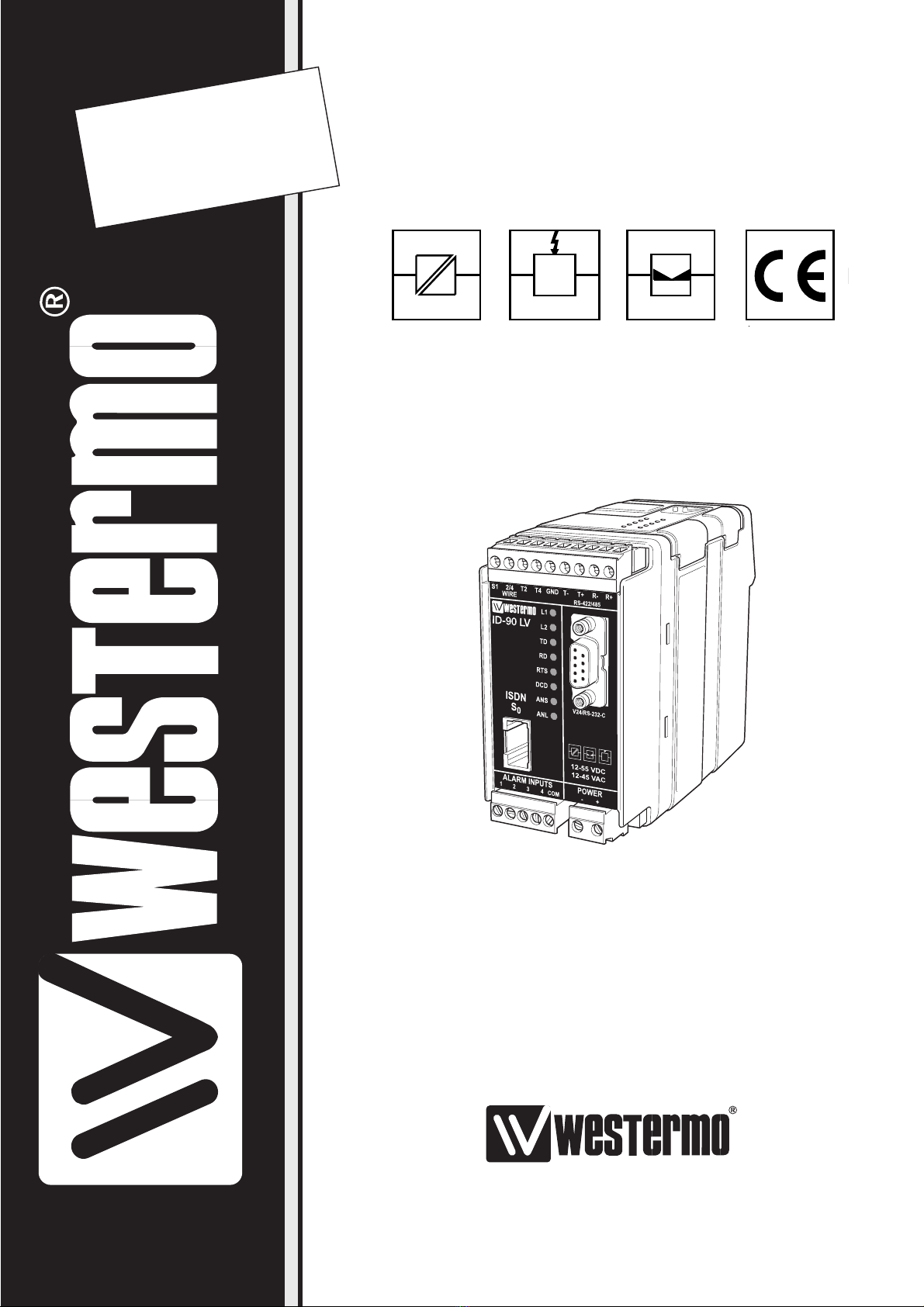
The Westermo ID-90 is an industrialised ISDN Terminal adapter. This Terminal adapter
has been developed with high speed industrial data communications in mind and has some
features you would not expect to find on normal adapters.
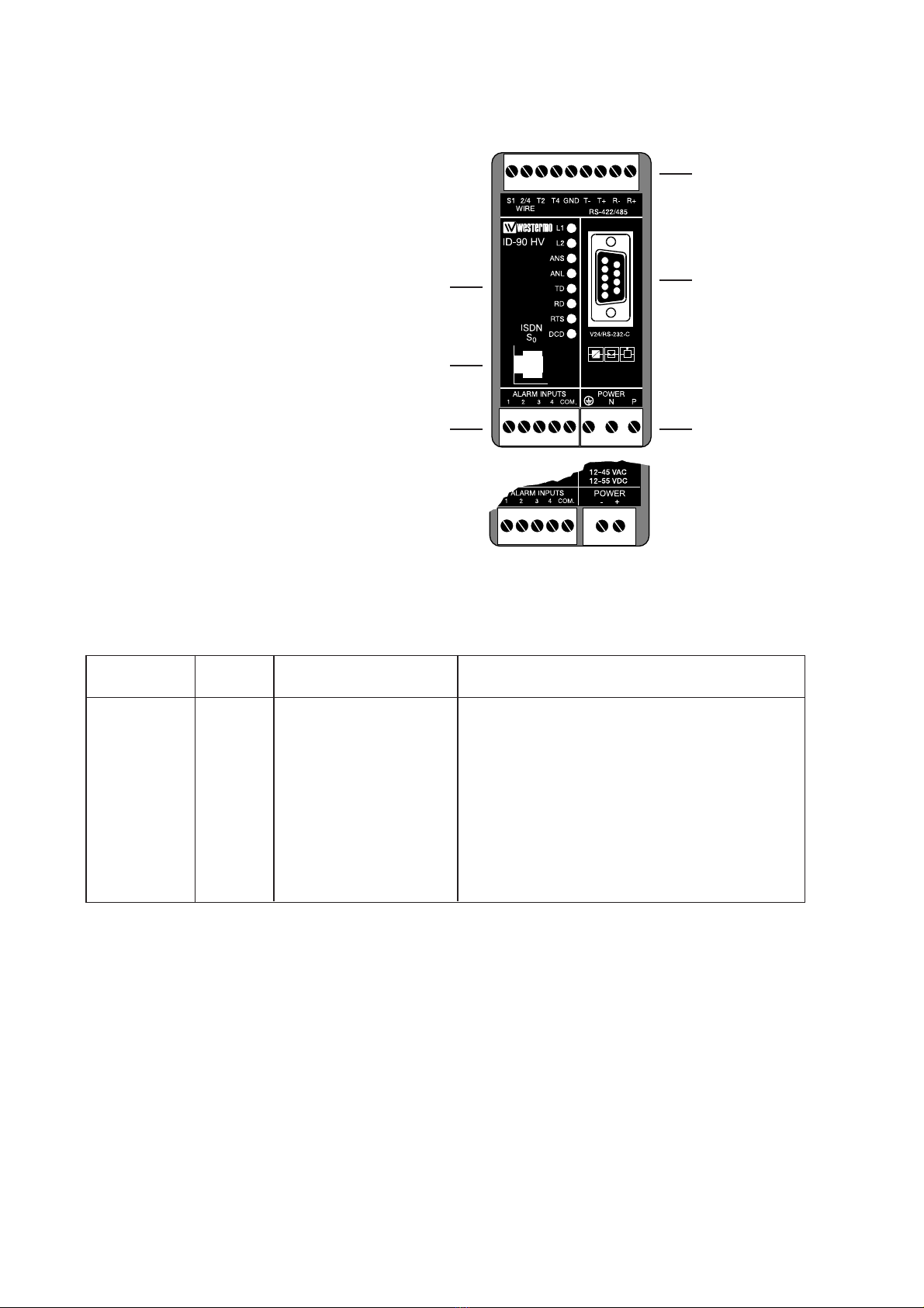
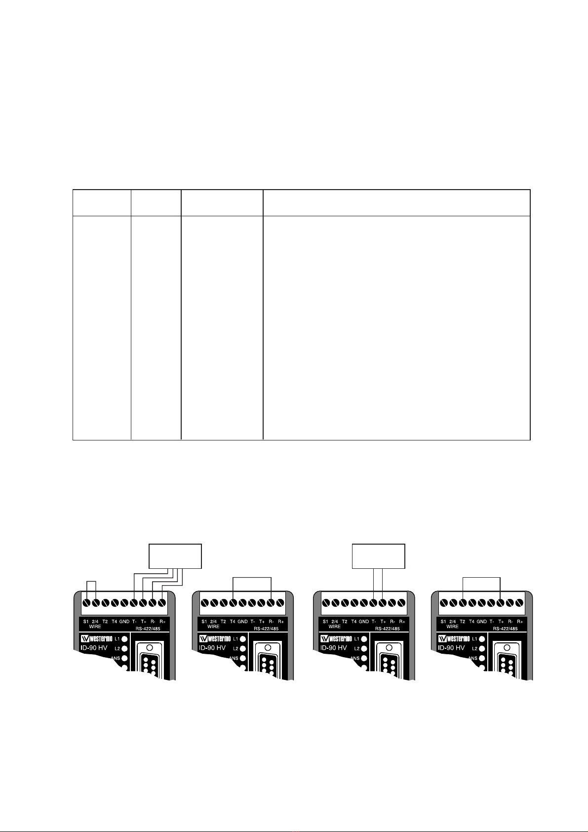
The unit is DIN rail mounted and has both an RS-232/V.24 and RS-485 interface in 2 or 4
wire connections.
Terminal data rates of up to 115.2 kbit/sec can be handled with a 128 kbit/s ISDN
B-channel bit rate.
The ID-90 has been designed to meet the European ISDN standard DSS1 as well as French
VN4. All standard ISDN transport protocols are supported including HDLC transparent, X75,
PPP and ML-PPP.
V.110 asyncronous is supported with flow control at data rates up to 19.2 kbit/sec.
A watchdog facility continually monitors the power supply and internal hardware as well
as the operational software. In the event of a problem the modem automatically resets.
This feature has been included to make the unit more suitable for use in unmanned loca-
tions.
The ID-90 is available in two standard versions:
One for high input voltages, version HV with nominal voltage range 95–240V AC and
110–240V DC ±10%.
One low voltage version, version LV with nominal input voltages 12–45V AC and
12–55V DC ±10%.
The ID-90 has 4 Alarm inputs that can be used to trigger 20 character SMS paging mes-
sages or establish automatic data connections, making the unit ideal for alarm monitoring
and remote diagnostics.
The ID-90 features DIP-switch configuration and can be programmed using AT-com-
mands, and a Configurator for local as well as remote configuration and CAPI 2.0
compatibility.
The ID-90 is also available in an optional configuration with an internal analogue V90
modem enabling connections from ISDN to analogue modem end locations.
The ID-90 has been designed with the engineer in mind, hence the extensive information on
the command set, S registers, DIP-switches and error codes. We have endeavoured to
include all necessary information however if you need more please do not hesitate to call us.
Safety
This equipment should only be installed by professional service personnel. If the unit is
intended for permanent connection to mains supply, there should be a readily accessible
disconnect device (circuit breaker) incorporated into the fixed wiring.
The ID-90 ISDN S0 is compliant to the requirement for TNV1 circuits for connection to
Telecommunication networks. The mains connection is classified as hazardous voltage
and the ID-90 classified as a Class I equipment.
The supply voltage to the Alarm input must use a SELV classified voltage source.
The RS-232/V.24 and RS-485 interface must only be connected to SELV circuits.
Description of the above classifications are given in SS-EN 60950 Issue 5.
The mains input is protected with a 1A, 250V time lag fuse. The fuse must only be replaced
with the same type and rating. Wickman type no: 19372 1A/250V or Littelfuse®664 001.

36607-2213
Specifications
Transmission Interface 1 Asynchronous, full/half duplex or simplex
PPP and M -PPP Asynchronous & Synchronous
conversion
V110 Asynchronous adaptation up to 19.2 kBit/s
Interface 2 B-channel protocols
V.110 async, V.120 async.
HD C async. to sync. HD C transparent
HD C transparent
Byte transparent
X.75 S P
X.25 B-Channel
T.70N and T.90N
PPP and M -PPP
D-channel protocols
Euro ISDN DSS1 and French VN4
X.31 Case B D-Channel
Interface 1 RS-232/V.24 9-pin D-sub female. RS-422 and
RS-485 2- and 4-wire with screw terminals
Interface 2 RJ-45
Transmission speed Interface 1 Up to 115.2 kbit/s
Interface 2 Up to 128 kbit/s
Command interface Interface 1 AT-command
Configurator remote/local
X3 PAD
Hotline DTR, TxD, Alarm call.
Alarm inputs Supply
voltage 10–60 V DC 1mA/input @ 10V DC
Power supply HV-version 95–240 V AC, 110–240V DC ±10%
LV-version 12–45 V AC, 12–55V DC ±10%
Power consumption HV-version 0.02A, 1.6W
With V90 option 0.05A, 3.5W
LV-version Max 0.1A, 1.2W
With V90 option 0.25A, 3.0W
Isolation S0Interface 1 500 V AC
Alarm 500 V AC
Mains 3 000 V AC
Indicator LED's TD, RD, DCD, RTS, 1, 2, ANS, AN
Temperature 5–50°C ambient temperature
Humidity 0–95% without condensation
Dimensions 55x100x128 mm (WxHxD)
Weight 0.4 kg
Mounting 35 mm DIN-rail

4
1234567
8
9
110-240 VDC
95-240 VAC
Installation
The Terminal Adapter should be connected in the following way:
Power connection is made through screw-block
at bottom right corner.
For HV-version a 3-pole connector,
and for LV-version a 2-pole connector is used.
Computers or other equipment
are connected through an
RS-232/V.24 or RS-485 connec-
tion. The RS-232/V.24 uses a
9-pole D-sub and the RS-485
a 9-pole screw connector.
Do not use ribbon cable
for RS-232/V.24 connections.
Light emit-
ting diodes
Screw-block
for RS-422/485
connection
9-pole D-sub
for RS-232/V.24
connection
Power
connection
Line connec-
tion RJ-45
Alarm
connection
▼ ▼ ▼
▼
▼
▼
RS-232/V.24 Connections
Pinouts for the 9-pole D-sub
O1 109 DCD/Data Carrier Detect
O2 104 RD/Received Data
I3 103 TD/Transmitted Data
I4 108/2 DTR/Data Terminal Ready
–5 102 SG/Signal Ground
O6 107 DSR/Data Set Ready
I7 105 RTS/Request to Send
O8 106 CTS/Clear to Send
O9 125 RI/Ring Indicator
Signal description
I= input O= output on ID-90
Direction Pin
no. CCITT V.24
Description
6607-2213
ID-90 LV

I1 R+ (A’) ID-90 Receive
I2 R– (B’) ID-90 Receive
I/O 3 T+ (A) ID-90 Transmit, at RS-485
I/O 4 T– (B) ID-90 Transmit, at RS-485 Bidirectional
–5 Shield If shielded cable is used, connect the shield
only at one end to avoid ground currents.
–6 T4 Termination 4-wire, connect to terminal 2
to terminate a 4-wire connection.
–7 T2 Termination 2-wire, connect to terminal 3
to terminate a 2-wire connection.
–8 2-/4-wire 2/4 wire input selector. Input open selects
2-wire and connected to terminal 9 for 4-wire.
–9 S1 Select 1. Wired to terminal 8 when 4-wire
connection is used. Internally connected to
+5V via pull-up resistor.
56607-2213
I= input O= output on ID-90
The definations R+/R–, T+/T– can be various between different manufactures.
ID-90 uses the defination that in a “MARK”-condition R+/T+ is more negative than R–/T–.
Description
Direction Terminal Name
RS-422/485 interface connection
The ID-90 is supplied with a RS-422/485 interface.
The RS-422/485 interface is internally in parallel to the RS-232/V.24 interface using the
9-pole D-sub. The two interfaces can not be used or be connected simultaneously, but the
interface connected will automatically be selected as the DTE source.
The RS-422/485 connections are made as shown below. Please note that the selection
of 2- or 4- wire and termination or no termination is done by linking between some of the
screw terminals.
Termination
4-wire Termination
2-wire
4-wire
Connection
of RS-422 Connection
of RS-485
1234567
8
9
1234567
8
9
1234567
8
9
1234567
8
9

66607-2213
Typical S0-bus connections
The Terminal equipment TE/TA like the ID-90 Terminal adapter can be connected to the
NT in 3 different ways always with a terminating resistor TR in each end of the bus, TR
should in all three cases be 100 ohm:
•Point to Point. In this configuration the ID-90 is the only TA on the S0bus.
A distance d1 of 1000 m is generally archived with a 0.3 mm240 nF/km cable.
•Short Passive Bus. The short passive bus puts no restriction on the distance between
units, but only specifying the maximum round trip delay to be 10 to 14 µs giving a d1
of 100 to 200 m depending on the cable impedance. Up to 8 ID-90 in combination with
other terminal equipment can be connected to the S0bus with a maximum connection
length d2 = 10 m.
1234567
8
9
TR TR
TA NT
ID-90
1234567
8
9
ID-90
d2
d1
GR 4 Fax
1234567
8
9
ID-90
TA TE
NT
TA
Point to Point Configuration
Short Passive Bus
Max 8 TA/TE
TR TR
d1
ISDN S0interface
The ISDN S0interface is connected via a 8-pol RJ-45 connector.
Pin Function
number
3 Transmit +
4 Receive
5 Receive
6 Transmit
1, 2, 7, 8 No connection
1
2
34
5678

76607-2213
•Extended Passive Bus. The difference between the short passive bus and the extended
passive bus is that the extended passive bus specifies a distance between the units, d3 and
that the units are located at the far end from the NT at a distance of d3 from the far end
terminating resistor TR. The range of d3 is from 25 to 50 m giving at least d1 =500 m.
(d2 see Short Passive Bus).
Diagram specifies practically achievable cable lengths as function
of cable capacitance for a 0.3 mm2wire.
1234567
8
9
ID-90
d2
d1
d3
GR 4 Fax
1234567
8
9
ID-90
TA TE
NT
TA
Extended Passive Bus
Max 8 TA/TE
TR TR
Cable capcitance [pF/m]

86607-2213
Alarm inputs
The four alarm inputs are accessed through screw terminals, the alarm inputs are opto-iso-
lated from all other parts of the ID-90. The alarm inputs need an external supply voltage of
10–60V DC to be operated. The supply is connected between the alarm input common and
the four inputs via making or breaking contacts. The inputs is not polarity sensitive but all
inputs must use the same common. The alarm inputs can use any mix of making and break-
ing contacts as the alarm trigger condition is programmable through AT-commands.
Example 1
Alarm through relay contacts.
Example 2
Alarm from a PLC with open collector.
110-240 VDC
95-240 VAC
110-240 VDC
95-240 VAC
10–60V DC
10–60V DC

6607-2213
LED Indicators
Indications via LED’s:
1 ISDN ine status ED normally showing the status of the ISDN S0interface.
1 together with 2 is also used to indicate error conditions
in the ID-90 and the connection to the ISDN S0interface.
2 ISDN Data connection ED Normally showing the state of the data connection
ANS Auto answer OFF = ID-90 will reject incoming calls.
ON = ID-90 will respond to incoming calls
AN Analogue line Only used when V.90 option installed.
OFF = No analogue connection established
B INK = Analogue call in progress
ON = Analogue line established
TD Transmit Data ED showing data from the DTE, the ED will blink when
data received
RD Receive Data ED showing data transmitted to the DTE, the ED will blink
when data transmitted
RTS Request to Send ED showing the status of the handshake line RTS from DTE,
ED is ON when DTE requests to send data.
DCD Data Carrier Detect ED showing the status of the handshake line DCD from ID-90,
The behavior of the DCD-line is programable, see configuration
command cdcd.
Active states:
L1 L2 Status Action
⊗Θ5x1s Start up phase
⊗Ο Connection to ISDN S0OK ; ISDN ok, no ISDN connection established
⊗∅ Call setup in progress
⊗⊕ Waiting for B channel
synchronization
⊗⊗ Data connection is
established
Error states:
1 2 Status
ΟΟ ID-90 NOT OK No power or Hardware error, check
power distribution, send ID-90 for repair
if necessary
Θ1x1s ΟConnection to ISDN S0Check ISDN interface/ -connector
NOT OK
ΟΘ2x1s ID-90 internal RAM error ID-90 repair necessary
ΟΘ1x1s ID-90 internal ROM error Reload Flash firmware, repair ID-90
if necessary
LED Legend:
⊗ON
∅Short on, long off Cycle 1 s
⊕ong on, short off Cycle 1 sec
ΘContinuous blinking: ntimes every mseconds, (nxms)
ΟOff

10 6607-2213
Data bits parity
When using DIP-swithes for parity and data bits
remember to set DTE baudrate switches as well.
DIP-Switch Setup
Disconnect power before changing DIP-switches.
Use ESD-protection when changing switches.
SW:1
SW:3 SW:4
SW:2
1234567
8
9
110-240 VDC
95-240 VAC
Stored setting from ID-90 database is used
S1 –
Related
AT-command
ON
12345678
No Parity 8-data bits
S1 AT**prty=0
AT**dbits=8
ON
12345678
Even Parity 8-data bits
S1 AT**prty=1
AT**dbits=8
ON
12345678
Odd Parity 8-data bits
S1 AT**prty=2
AT**dbits=8
ON
12345678
Not used
S1 –
ON
12345678
Not used
S1 –
ON
12345678
Even Parity 7-data bits
S1 AT**prty=1
AT**dbits=7
ON
12345678
Odd Parity 7-data bits
S1 AT**prty=2
AT**dbits=7
ON
12345678

116607-2213
DSR and DCD line control
Stored setting from ID-90 database is used
S1 –
Related
AT-command
ON
12345678
DTR line control
Stored setting from ID-90 database is used
S1
S1
–
Related
AT-command
ON
12345678
ON
12345678
ON
12345678
ON
12345678
ON
12345678
ON
12345678
ON
12345678
ON
12345678
ID-90 control line
DSR and DCD is always ON
S1 AT&S
AT&C
DSR is always ON
DCD ON indicates ISDN connection is established and synchronized
S1 AT&S
AT&C1
DSR ON indicates ISDN connection is established and synchronized
DCD always ON
S1 AT&S1
AT&C
DSR ON indicates ISDN connection is established and synchronized
DCD ON indicates ISDN connection is established and synchronized
S1 AT&S1
AT&C1
ON
12345678
DTR is evaluated: Ignored AT&D
AT**cdtr = 0
S1
ON
12345678
DTR is evaluated: Dropping the DTR line by the DTE will
disconnect an existing ISDN connection.
An incoming call will be accepted only with DTR active
AT&D2
AT**cdtr = 2
Reserved
S1 –
Reserved
S1 –
DSR and DCD follows DTR
S1 AT**cdsr=2
AT**cdcd=2
S1
ON
12345678
DTR is evaluated: Incoming calls will be accepted independent of
DTR status; DTR drop disconnects an active connection AT&D4
AT**cdtr = 4

12 6607-2213
DTE baudrate
Stored setting from ID-90 database is used
S2
ON
1234
Automatic baud detection AT%B0
–
Related
AT-command
S2
ON
1234
1 200 bit/s AT%B1
S2
ON
1234
2 400 bit/s AT%B2
S2
ON
1234
4 800 bit/s AT%B3
S2
ON
1234
9 600 bit/s AT%B4
ON
1234
S2
19 200 bit/s AT%B5
ON
1234
S2
38 400 bit/s AT%B6
ON
1234
S2
57 600 bit/s AT%B7
ON
1234
S2
115 200 bit/s AT%B8
ON
1234
S2

136607-2213
B-Channel protocol
Stored setting from ID-90 database is used
S3 –
Related
AT-command
ON
12345678
V.110 asynchronous
S3 ATB0
ON
12345678
HD C asynchronous to synchronous conversion
(for PPP asynchronous and single link PPP)
S3 ATB3
ON
12345678
HD C transparent
(DTE data octets packed into HD C frames)
S3 ATB4
ON
12345678
Byte transparent (raw B-channel data)
S3 ATB5
ON
12345678
X.75 S P
S3 ATB10
ON
12345678
V.120 asynchronous
S3 ATB13
ON
12345678
X25 / X31 B channel (X.25 B channel)
S3 ATB20
ON
12345678
X25 / X31 D channel
S3 ATB21
ON
12345678
T.70-N -CEPT
S3 ATB22
ON
12345678
T.90-N
S3 ATB23
ON
12345678
M -PPP Multilink PPP
S3 ATB31
ON
12345678

14 6607-2213
Command set
Selects the flow control behaviour of the ID-90 while in data communication phase.
Stored setting from ID-90 database is used
S3 –
Related
AT-command
ON
12345678
AT-command set
S3 AT**cmds = 0
ON
12345678
X.3 PAD
S3 AT**cmds = 1
ON
12345678
Hot line DTR call
S3 AT**cmds = 6
ON
12345678
Hot line TxD call
S3 AT**cmds = 7
ON
12345678
Reserved
S3 –
ON
12345678
Configurator
S3 AT**cmds = 10
ON
12345678
Incomming call handling
Stored setting from ID-90 database is used
S3 –
Related
AT-command
ON
12345678
Reject all incoming calls
S3 AT#R1
ON
12345678

156607-2213
Flow control
Selects the flow control behaviour of the ID-90 while in data communication phase.
Stored setting from ID-90 database is used
S4 –
Related
AT-command
ON
12345678
No local flow control between the DTE and ID-90 is used
CTS is always ON, RTS ignored
S4 AT&K
AT&R1
ON
12345678
No local flow control between the DTE and ID-90 is used
CTS follows DTR, RTS ignored
S4 AT&K
AT&R2
ON
12345678
No local flow control between the DTE and ID-90 is used
CTS follows changes on RTS
S4 AT&K
AT&R
ON
12345678
ocal flow control is set to hardware handshake RTS/CTS
S4 AT&K3
ON
12345678
ocal flow control is set to software handshake XON/XOFF
CTS is always ON, RTS ignored
S4 AT&K4
AT&R1
ON
12345678
ocal flow control is set to software handshake XON/XOFF
CTS follows DTR, RTS ignored
S4 AT&K4
AT&R2
ON
12345678
ocal flow control is set to software handshake XON/XOFF
CTS follows changes on RTS
S4 AT&K4
AT&R
ON
12345678
Software update
Enable Flash programming, should always be in OFF position
for normal operation, ref. software update
S4
ON
12345678
Selection of analogue coding V- 0
A- aw, European analogue data coding standard
S4
ON
12345678
µ- aw, US analogue data coding standard
S4
ON
12345678

16 6607-2213
Default setting from ID-90 database is used
S4 –
Related
AT-command
ON
12345678
1 200 bit/s
S4 ATN1
ON
12345678
2 400 bit/s
S4 ATN2
ON
12345678
4 800 bit/s
S4 ATN3
ON
12345678
9 600 bit/s
S4 ATN4
ON
12345678
19 200 bit/s
S4 ATN5
ON
12345678
Line baudrate at V.110
The ID-90 DIP-switches will be read at Power on and override the current database set-
ting. If an AT-command or Configurator command given after Power on addressing the
same parameter as a DIP-switch setting the command will in turn override the DIP-switch
setting.
A Save command AT&W will store the current configuration set by DIP-switches or
configuration commands.
Factory settings
S1
ON
12345678
S2
ON
12345678
S3
ON
12345678
ID-90 V.90
S4
ON
12345678
S1
ON
12345678
S2
ON
12345678
S3
ON
12345678
ID-90
S4
ON
12345678

176607-2213
OWN COMMENTS
.....................................................................................................................................................................................................................
.....................................................................................................................................................................................................................
.....................................................................................................................................................................................................................
.....................................................................................................................................................................................................................
.....................................................................................................................................................................................................................
.....................................................................................................................................................................................................................
.....................................................................................................................................................................................................................
.....................................................................................................................................................................................................................
.....................................................................................................................................................................................................................
.....................................................................................................................................................................................................................
.....................................................................................................................................................................................................................
.....................................................................................................................................................................................................................
.....................................................................................................................................................................................................................
.....................................................................................................................................................................................................................
.....................................................................................................................................................................................................................

18 6607-2213
OWN COMMENTS
.....................................................................................................................................................................................................................
.....................................................................................................................................................................................................................
.....................................................................................................................................................................................................................
.....................................................................................................................................................................................................................
.....................................................................................................................................................................................................................
.....................................................................................................................................................................................................................
.....................................................................................................................................................................................................................
.....................................................................................................................................................................................................................
.....................................................................................................................................................................................................................
.....................................................................................................................................................................................................................
.....................................................................................................................................................................................................................
.....................................................................................................................................................................................................................
.....................................................................................................................................................................................................................
.....................................................................................................................................................................................................................
.....................................................................................................................................................................................................................


6607-2213 02.08 Mälartryck AB, Eskilstuna, Sweden
Westermo Teleindustri AB • SE-640 40 Stora Sundby, Sweden
Phone +46 16 42 80 00 Fax +46 16 42 80 01
E-mail: info@westermo.se • Westermo Web site: www.westermo.se
WestermoTeleindustri AB have distributors in several
countries, contact us for further information.
Westermo Data Communications Ltd
Unit 14 Talisman Business Centre • Duncan Road
Park Gate, Southampton • SO31 7GA
Phone: +44(0)1489 580 585 • Fax.:+44(0)1489 580586
E-Mail: sales@westermo.co.uk • Web: www.westermo.co.uk
Westermo Data Communications GmbH
Goethestraße 67, 68753 Waghäusel
Tel.: +49(0)7254-95400-0 • Fax.:+49(0)7254-95400-9
E-Mail: info@westermo.de • Web: www.westermo.de
Westermo Data Communications S.A.R.L.
9 Chemin de Chilly 91160 CHAMPLAN
Tél : +33 1 69 10 21 00 • Fax : +33 1 69 10 21 01
E-mail : infos@westermo.fr • Site WEB: www.westermo.fr
Subsidiaries
Table of contents
Other Westermo Adapter manuals

Westermo
Westermo ED-10 TCP User manual

Westermo
Westermo EDW-100 EX User manual

Westermo
Westermo FD-10 User manual

Westermo
Westermo ED-10 TCP User manual

Westermo
Westermo EDW-120 User manual

Westermo
Westermo AD-01 User manual

Westermo
Westermo EDW-100 User manual

Westermo
Westermo IDW-90 User manual

Westermo
Westermo EDW-120 User manual