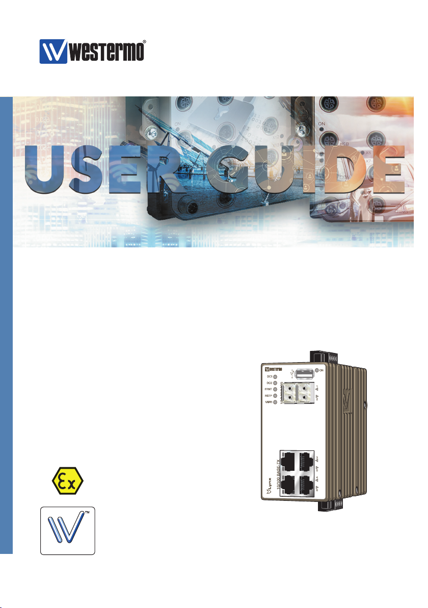
Westermo Lynx DSS L106-F2G EX User manual
Other Westermo Switch manuals

Westermo
Westermo Lynx L106-S2 User manual

Westermo
Westermo Viper-120A-P8-HV User manual

Westermo
Westermo Lynx DSS L108-F2G-S2 EX User manual

Westermo
Westermo MDI-110 Series User manual

Westermo
Westermo RedFox 7528 Series User manual

Westermo
Westermo Lynx DSS L108-F2G-S2 EX User manual

Westermo
Westermo Lynx L206-F2G-EX User manual

Westermo
Westermo Viper-8 Series User manual

Westermo
Westermo RedFox-5528-E-T28G-LV User manual

Westermo
Westermo Lynx DSS L108-F2G-S2 EX User manual

Westermo
Westermo Lynx SERIES User manual

Westermo
Westermo Viper 12A Series User manual

Westermo
Westermo Lynx L206-F2G User manual

Westermo
Westermo RFI-211-T3G User manual

Westermo
Westermo Lynx DSS L206-S2-EX User manual

Westermo
Westermo Lynx L110 F2G EX User manual

Westermo
Westermo Viper 108 User manual

Westermo
Westermo Viper TBN Series User manual

Westermo
Westermo Lynx DSS L206-S2 User manual

Westermo
Westermo MRI-128-F4G-PSE Series User manual