Western Electric 1A User manual

1A
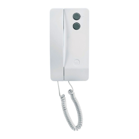
HOME
INTERPHONE
TCI Library: www.telephonecollectors.info

1A
HOME
INTERPHONE
This
manual
contains
material
reproduced
from
Bell Sys-
tem
Practices
with
permission
of
the
copyright
proprietor.
Copyright
1960,
American
Telephone
and
Telegraph
Company.
TCI Library: www.telephonecollectors.info

1.00
2.00
3.00
4.00
5.00
6.00
7.00
8.00
9.00
10.00
General
Identification
Operation
.
Installation
Components
TABLE OF CONTENTS
Location
and
Mounting
System
Adjustment
Maintenance
.
Trouble
Location
.
Connections .
11.00
Testing
of
Circuits
Containing
Diodes,
Varistors,
or
Transistors
Illustrations
Fig.
1 -511DRW Telephone
Set
Modified
to
Include
660A
Transmitter
Unit
.
Fig.
2 -
558DRW
Telephone
Set
Modified
to
Include
659A
Transmitter
Unit
Fig.
3 -711BW Telephone
Set
Modified
to
Include
664A
Transmitter
Unit
.
Fig.
4 -2012A
or
KS-16184
Transformer.
Fig.
5 -
lA
Home
Interphone
.
Fig.
6 - 659A
Transmitter
Unit
Mounted in
558DRW
Telephone
Set
.
Fig.
7 -660A
Transmitter
Unit
Mounted
in
511DRW
Telephone
Set
.
Fig.
8 -Location
of
664A
Transmitter
Unit
Components
in
711BW Telephone
Set
Fig.
9 -
Final
Assembly
of
664A
Transmitter
Unit
in
711BW Telephone
Set
Fig.
10 -759AW
Loudspeaker
.
Fig.
11 -730AW Receiver
Fig.
12 -Amplifier Gain
Controls
Fig.
13 -
Wiring
Board
Assembly Removal
Fig.
14 -711BW Telephone
Set
Connections
to
lA
Home
Interphone
Fig.
15 -511DRW
or
558DRW Telephone
Set
Connections
to
lA
Home
Interphone
Fig.
16 -511DRW Telephone
Set
Connections
to
lA
Home
Interphone
Fig.
17 -558DRW Telephone
Set
Connections
to
lA
Home
Interphone
Fig.
18 -711BW Telephone
Set
Connections
to
lA
Home
Interphone
1
1
3
4
5
5
9
9
12
13
13
1
2
3
3
4
5
6
7
7
8
8
10
10
12
15
17
18
19
TCI Library: www.telephonecollectors.info

1A
HOME
INTERPHONE
1.00
GENERAL
1.01
The
lA
home
interphone
provides
central
office
line
pickup
and
hold-
ing,
interphone
between
stat.ions,
and
door-
answering
features.
1.02
Central
office
line
pickup
is
provided
at
all
stations.
1.03
Central
office
line
holding
is
provided
at
all
lA
home
interphone
stations.
1.04
Interphone
calls
originate
from
tele-
phone
handset;
operation
is
hands-
free
at
called
stations.
1.05
The
lA
home
interphone
is
limited
to
five
telephone-set
locations.
l.06
Door
units
may
be
answered
from
any
lA
home
interphone
telephone-
set
location.
1.07
The
lA
home
interphone
is
limited
to
two
door-answering
units.
2.00
IDENTIFICATION
2.01
The
lA
home
interphone
consists
of
the
following
components:
Telephone
sets:
511DRW, 558DRW,
or
711BW.
Transmitters:
659A, 660A,
or
664A.
Control
unit,
51AW.
Receiver
(door-answering
unit),
730AW.
LINE
KEY
Fig. 1 -
511DRW
Telephone
Set
Modified to lnclnde 660A
Transmitter
Unit
l
TCI Library: www.telephonecollectors.info

Fig. 2 -
558DRW
Telephone
Set
Modified to Include 659A
Transmitter
Unit
664A
TRANSMITTER
LINE
KEY
PUSH
BUTTON
Fig. 3 -
711BW
Telephone
Set
Modified to Include 664A Tran.>mitter Unit
2
TCI Library: www.telephonecollectors.info

Loudspeaker,
759AW.
Transformer,
2012A
or
KS-16184.
2.02
The
511DRW, 558DRW,
and
711BW
telephone
sets
are
modified
by
add-
ing
the
660A, 659A,
and
664A
transmitter
units,
respectively.
These
function
as
micro-
phones
to
provide
the
hands-free,
talk-back
interphone
feature.
2.03
The
51AW
Control
Unit
consists
of:
Apparatus
box
similar
to
but
larger
than
a 105
apparatus
box.
Terminal
board
to
connect
wiring
from
one
to
five
telephone
sets.
Printed-wiring
board
which
includes
the
transistorized
microphone
and
loudspeaker
amplifiers,
and
power
supply.
15-TO
8 - VOLT
TERMINALS
Fig. 4
-2012A
or KS-16184
Transformer
3.00 OPERATION
OF
1A HOME INTERPHONE
3.01
Telephone-set-line-key
position
for:
511DRW
and
558DRW
()\
telephone
set:
A
dual
wire
spring
relay
which
--
switches
between
the
interphone
and
711BW
Telephone
set:
door
answering
1 and supplies power
to
the
amplifiers.
2.04
The
759AW
Loudspeaker
·
consists
of
a
dynamic
loudspeaker
and
a
12-terminal
connecting
block.
They
are
mounted
on a
metal
base
and
covered
with
a
plastic
housing.
The
loudspeaker
provides
hands-free
interphone
reception.
2.05
The
730AW
Receiver
consists
of
a
dynamic
loudspeaker,
a modified
Ul
receiver unit, and a 2-terminal connecting
block.
They
are
mounted
on
a
metal
base
and
covered
with
a
weatherproof
plastic
housing.
The
730AW
receiver
provides
hands-free
communication
at
door
locations.
2.06
The
2012A
or
KS-16184
Transformer:
Encased
in ceramic.
Operates
on 105
to
130
volts
60
cycles.
Secondary
voltage:
6
to
8
volts
60
cycles.
Plugs
directly
into
an
electric
outlet
by
means
of
two
protruding
prongs.
Supplies
power
for
51AW
control
unit
or
dial
light.
3.02
Central
Office
Connection:
0
or
\~c::::J-~
With
line
key
in
position
shown,
tele-
phone
set
is
connected
for
incoming
and
outgoing
service.
Ringer
will
operate
on
in-
coming
calls
with
line
keys
in
either
posi-
tion.
3.03
Central
Office
Line
Holding:
Central
office
line
may
be
held,
to
answer
interphone
or
door
units,
by
operat-
ing
the
hold
key.
To
re-establish
central
office
connection,
operate
line
key
to
cen-
tral
office
position
and
depress
hold
key.
3.04
Interphone:
=
or
With
line
key in
position
shown,
as-
sociated
handset
can
communicate
with
all
interphone
stations
simultaneously.
Called
interphone
stations
may
answer
hands-free
or
use
the
handset
with
line
key
in
inter-
phone
position.
TCI Library: www.telephonecollectors.info

3.05 Door Answering:
0
or
[§Ji
With
line
key
in
position
shown,
off-
hook
station
is
transferred
from
interphone
to
door
answering
by
momentarily
depress-
ing
push
button.
To
transfer
to
interphone,
momentarily
operate
switchhook
or
operate
line
key
to
central
office
line
position
and
back
to
interphone.
1A
HOME
INTERPHONE
!INSTALLATION!
4.00
GENERAL
4.01
The
lA
home
interphone
is
limited
to
five stations and two door-answering
units.
Sample
arrangements
are
shown
in
Fig.
5.
4.02
Dial-light
power
is
furnished
from
a
separate
2012A
or
KS-16184
trans-
former.
4.03
When
installing
a
dial
light
trans-
former,
make
certain
that
telephone
protector
and/or
signaling
ground
conduc-
tor
is
connected
to
the
best
ground
avail-
able.
Damage
to
the
transformer
may
re-
sult
if
a sufficient
difference
of
po-
tential
is
allowed
to
develop
between
the
power
and
telephone
grounds.
Because
difference
of
ground
poten-
tial
appears
between
the
windings
of
the
transformer,
voltage
from
a
lightning
surge
could
break
down
the
insulation
between
the
windings.
Fig. 5
-1A
Home Interphone
TCI Library: www.telephonecollectors.info

5.00 COMPONENTS OF 1A HOME
INTERPHONE
The
following
units
are
ordered
sep-
arately:
Control
unit,
51AW.
Telephone
sets,
511DRW, 558DRW,
or
711BW.
Transmitter
units,
659A, 660A,
or
664A.
Receiver
unit
(door
answering),
730AW.
Loudspeaker
unit,
759AW.
Adapter
assembly,
146A.
Transformer,
2012A
or
KS-16184.
6!5!11A
TRANSMITTER
UNIT
6.00
LOCATION AND
MOUNTING
6.01
The
51AW
control
unit
is
mounted
upright
on a
vertical
surface.
6.02
659A
and
660A
transmitter
units
are
mounted
in
telephone
sets
as
shown
in
Fig.
6 and 7.
6.03
The
664A
transmitter
differs
from
the
659A
and
660A
transmitter
in
that
it
is
not
a one-piece
unit.
The
trans-
mitter
unit
and
bracket
are
installed
on
the
cord
terminal
strip
while
the
component
board
assembly
is
installed
under
the
dial
as
shown
in
Fig.
8
and
9.
Be
certain
that
the
transmitter
bracket
is
connected
to
ter-
minal
9
on
the
cord
terminal
strip
and
lies
between
the
two
molded
pegs
of
the
termi-
nal
strip
as
shown.
The
component
board
LINE
KEY
Fig. 6 -659A
Transmitter
Unit Mounted
in
558DRW
Telephone
Set
5
TCI Library: www.telephonecollectors.info

Fig. 7 -660A Trrmsmitter Unit i\!Iounted in 511DRW Telephone
Set
assembly
is
notched
on one
end
to
fit in
the
slots
of
the
dial
mounting
bracket
and
is
held
in
place
by
a
screw
in
the
other
end.
The
board
is
placed
so
that
the
components
are
on
the
under
side
when
installed.
Fig.
8
shows
a
transmitter
and
board
assembly
partially
installed.
Fig.
9
shows
the
com-
pleted
installation.
6.04
Care
should
be
exercised
to avoid
puncturing
or
otherwise
dan1aging
the
delicate
membrane
covering
of
the
N-type
transmitter
unit.
Damage
may
re-
sult
in
poor
transmission
quality.
6.05
The
759AW
loudspeaker
is
drilled
to
mount
on a 63A
bracket
or,
by
using
a 146A
adapter
assembly,
it
may
be
mounted
on
a
standard
electrical
outlet
box. A
back-
board
is
not
required
for
mounting.
Four
mounting
holes
are
provided
in
the
base
for
securing
to
the
mounting
surface.
The
cord
and
cable
may
enter
through
two
boles
pro-
vided
in
the
base
or
through
the
end
by
removing
the
knockouts.
The
12-terminal
6
connecting
block
serves
as
a
junction
for
the
telephone
set
cord
and
a
6-pair
cable
from
the
wall
telephone
set
or
51AW
con-
trol
unit. A
cord
hook is
provided
on
the
connecting
block
to
anchor
the
set
cord
(see
Fig.10).
6.06
The
730AW
receiver
(door-answer-
ing),
see
Fig.
11, is
mounted
on
the
door
casing
or
outside
wall
at
a
convenient
height
for
microphone
pickup
and
out
of
reach
of
children.
If
this
location
is
not
de-
sirable,
the
speaker
may
be
mounted
over-
bead
just
above
the
door.
Four
mounting
holes
are
provided
in
the
base
similar
to
those
in
the
759AW
loudspeaker.
Wiring
may
enter
through
two
holes
provided
in
the
base
or
through
the
end
of
the
base
by
removing
the
knockouts.
A
backboard
is
not
required
for
mounting.
The
730AW
receiver
is
weatherproof.
Additional
weather
protec-
tion
is
not
required.
Cable
pair
is
run
di-
rectly
to
Ul
receiver
unit
and
connected
to
screw
terminals
on
the
bottom
of
the
unit.
.it
TCI Library: www.telephonecollectors.info

GORD
TERMINAL
'"*g
\
TRANSMITTER
\
BRACKET
SLOT
iN
DIAL
BRACKET
COMPONENT
BOARD
Fig.
8-Location
of 664A
Transmitter
Unit Components
in
711BW
Telephone
Set
DRESS
LEADS
AROUND
PLUNGER
CONTACTS
Fig. 9 -Final
Assembly
of 664A Tra,nsmitter Unit
in
711BW
Telephone
Set
7
TCI Library: www.telephonecollectors.info

8
CONNECTING
BLOCK
CORO
HOOK
LOUDSPEAKER
CONNECTING
BLOCK~~~~~-
MOUNTING
HOLE
MOUNTING
HOLE
Fig.
10---,-
759AW Loudspeaker
UI
RECEIVER
MOUNTING
HOLE
Fig.
11
-
730AW
Receiver
TCI Library: www.telephonecollectors.info

6.07
The
146A
adapter
assembly
is
pro-
vided
to
mount
the
730A
W
receiver
or
759A
W
loudspeaker
to
a
standard
elec-
trical-outlet
box.
It
is
drilled
and
tapped,
and
screws
are
provided
for
mounting.
6.08
The
2012A
or
KS-16184
transformer
plugs
directly
into
a
standard
105-
to
130-volt
60-cycle
convenience
outlet.
The
6-
to
8-volt
60-cycle
power
for
the
51A
W
control
unit
appears
on
the
two
screw
ter-
minals.
Transformer
must
operate
from
a
power
outlet
not
controlled
by
a
switch.
7.00
SYSTEM
ADJUSTMENT
7.01
System
adjustment
requires
that
mi-
crophone
and
loudspeaker
amplifier
gain
controls
be
adjusted
to
satisfy
customer
requirements.
If
properly
adjusted, there
should be no "sing" or "squeal" when
any
handset
is
removed.
7.02
Turn
microphone
and
loudspeaker
amplifier
gain
controls
to
their
maxi-
mum
counterclockwise
(minimum
gain)
po-
sition
(see
Fig.
12).
7.03
All
station
handsets
must
be
in
the
on-hook
position.
7.04
Connect
1011BW,
or
equivalent,
test
set
to
terminals
2R
and
2T
on
51A
W
control
unit
with
switch
in
TALK
position.
7.05
Microphone
amplifier
adjustment:
Turn
microphone
amplifier
gain
con-
trol
clockwise
1/8
turn.
7.06
Loudspeaker
amplifier
adjustment:
Turn
loudspeaker
amplifier
gain
con-
trol
clockwise
until
a
squeal
is
heard
in
the
test
set.
Turn
loudspeaker
amplifier
gain
con·
trol
counterclockwise
until
the
sing·
ing
or
squealing
stops.
7.07
When
possible,
have
the
customer
check
the
operation
to
ensure
satis-
factory
adjustment.
7.08
If,
after
adjustment,
the
gain
is
not
at
a
satisfactory
level,
it
may
be
in·
creased
somewhat
by
the
following
method.
1.
Proceed
as
in
7.02.
2.
Lift
the
handset
from
one
of
the
interphonc
stations
to
off-hook
position.
Be
sure
that
the
line
switch is in the interphone posi-
tion.
3.
Connect
1011BW,
or
equivalent
test
set,
to
terminals
2R
and
2T
on
51A
W
control
unit
with
test
set
switch
in
MONITOR
position.
4.
Proceed
with
adjustments
as
in
7.05
and
7.06.
5.
Remove
lOllBW
test
set
and
re-
store
station
handset
to
on-hook
position.
7.09
Final
check
of
interphone
and
door
answering
features:
1.
Operate
line
key
to
INTER-
PHONE
position
at
test
station.
2.
Remove
handset.
3.
Test
microphone
sensitivity
and
loudspeaker
volume
at
all
loca-
tions
in
the
house.
4.
Momentarily
depress
pushbutton.
5.
Test
door-answering
unit
for
sat-
isfactory
loudspeaker
volume
and
microphone
sensitivity.
Note:
Microphone
and
loud-
speaker amplifiers are now ad-
justed
for
satisfactory
operation
at
all
locations.
Any
change
in
settings
will
affect
the
levels
of
both
the
telephone-set
locations
and
the
door-answering units.
8.00 MAINTENANCE
Caution: Tests on 51AW Control Unit,
Using a Test Receiver or 1011BW, or
equivalent Test
Set,
Must Be Confined
to the
Terminal
Borrrd. Proceed as in
11.00
When
Working
on Circuits Con-
taining Diodes, Varistors, or Tran-
sistors.
9
TCI Library: www.telephonecollectors.info

10
LOUDSPEAKER GAIN
MICROPHONE
GAi
N
'-.__WIRING
BOARD
ASSEMBLY
Fig. 12
-Amplifier
Gain Controls
•""'1
..
\\ll
'!Ir
Fig. 13 -
Wiring
Board A.ssembly Removal
I
~
J
TCI Library: www.telephonecollectors.info

.j,
f~)
•
8.01
Maintenance
of
51AW
control
unit
should
be
limited
to
replacement
of:
Wiring
board
assembly
P-11E655.
51A
W
control
unit.
8.02
Wiring
board
assembly
is
removed
from
the
51AW
control
unit
by
re-
moving
the
four
mounting
screws
and
pull-
ing
the
board
away
from
the
jack
connector
(see
Fig
13).
TABLE
A
TROUBLE
LOCATION INFORMATION
Trouble Trouble
Test
Test Trouble
Indications
Cause
for
Equipment
Correction
AC
Power
105
to
130V
AC
Trouble
Restore
outlet
Failure
at
Outlet
Lamp
power.
2012A
or
6
to
8V
AC
Voltmeter
Replace
transform-
KS-16184
Term.
Pl-P2
AC
scale
er
or
wire
to
trans-
Transformer
on
51AW
Unit
former.
Power
Supply
Interphone
Installer
Test
Replace
amplifier
Interphone
or
Set
on
Term.
Dead
Amplifiers
Talk
Battery
2T
and
2R
(51AW)
board.
Clean
relay
con-
Interphone
Installer
Test
tacts
KlA
Relay
Set
on
Term.
or
Talk
Battery
2T
and
2R
(51AW)
Replace
51A
W con-
trol
unit.
All
Clean
relay
con-
Microphones
Contacts
of
tacts.
KlB
Relay
Replace
amplifier
Dead,
Amplifier
board.
Loudspeakers
Board
Replace
51A
W con-
OK
trol
unit.
All
Clean
relay
con-
Loudspeakers
Contacts
of
tacts.
KlB
Relay
Replace
amplifier
Dead,
Amplifier
board.
Microphones
Board
Replace
51A
W con-
OK
trol
unit.
Door
Units
Contacts
of
Clean
relay
con-
Dead,
KlA
Relay
tacts
or
Interphone
or
Replace
51A
W con-
Dead
KlB
Relay
trol
unit
.
11
TCI Library: www.telephonecollectors.info

HA
9.00
TROUBLE
LOCATION
9.01
Table
A is
furnished
to
assist
in lo-
cating
trouble
in
the
lA
home
inter-
phone.
9.02
Trouble
indications
listed
are,
in gen-
eral,
limited
to
common
troubles
which
may
occur
in
the
51AW
control
unit.
9.03
Individual
station
troubles
may
be
corrected
by
using
the
connection
in-
formation
or
schematic
drawings
(Fig.
14
and
15).
ND
SET
664A
XMTR
•
DIAL
SWITCHHOOK
NIGHT-
HOLD
KEY
LINE
TERM.
MTG
IN
BA
ASSEMBLY
LIGHT
KEY
TEL
SET
SWITCH
----------i
. 10
11
IR
I IRl
l
..
I
IW)
9
N2
IWl
I
{Sl
? E2j
ISl
'l
IS-Y)
.,
ISl t
/<-RR)
IBKl 4
.2T
'
-----
-I
{S
G) •
NETWORK
Fj
(BL}
l v
(G)
2
IT
~
(BL)
.
..
-~
vT
(R-Y)
{W)
•
,-
.\(W)
~
{G-'!'l *
R
CVR
r~~
• j w
=c
t (BL)
TR
RR
{Gl -IRI
1'J
1R
<
fi'IRl
J.
(S
Gl
L2
(S-R)
. . d -t
{Y)
302R
/R
c IS)
te
XM
(BK)
B
GN
(5-R)
IW)
7
RI
(W)_
j t 8
[0-BK)
f
•g
(S-BL)
k j
S!J
{S-R)
4
0i
J-
l
~
{S-G)
I
Note
1:
Connect
terminal
7
white
lead
to
terminal
5
of
759AW
loudspeaker.
Nole
2:
Connect
terminal
3
brown-red
lead
10) 2
and
terminal
4
brown-green
lead
to
t~r-
«0
minals
12
and
11,
respectively,
of
759AW
rc=i:;
1§
£%
_3.
loudspeaker.
,,,,;
LAMP
1£9:
I*
Ta
e
ends
individuall
GE
N0.46~
p y
Fig.
14-
711BW
Telephone
Set
Connections to
1A
Home Interphone
12
MTG
CORD
D
14H
IO-RK\
{O)
/BR-BK\
*
ilRR-Y\
IBKl
{G)
1)
R)
!IY)
<Wl
'J
IBLI
(BR-,G)
SEE
NOTE
2-
(BR-Al
I
TCI Library: www.telephonecollectors.info

1A
HOME
INTERPHONE
!CONNECTIONS!
10.00
G<NERAL
10.01
Information
shown
in
Fig.
16
through
18
should
be
used
for
lA
home
inter-
phone
equipment
connections.
10.02
Connection
of
additional
dial-light
transformer
to
terminals
P3
and
P4
is
made
only
when
station
requires
dial-
light
power.
10.03
When
only
one 730AW
receiver
(door
answering)
is used,
the
12-ohm
re-
sistor
should
remain
connected
to
terminal
S3 on
the
51AW
control
unit.
10.04
When
adding
a
second
730AW
re-
ceiver
(door
answering),
remove
the
12-ohm
resistor
lead
from
terminal
S3
on
the
51AW
control
unit.
I
0.05
To
modify
telephone
sets
to
adapt
to
lA
home
interphone,
see
Fig.
16, 17,
and
18.
10.06
lA
home
interphone
cannot
be con-
nected
for
tip-party
identification.
TESTING OF CIRCUITS
CONTAINING
DIODES, VARISTORS, OR TRANSISTORS
11.00
GENERAL
11.01
When
testing
a
circuit
containing
diodes,
varistors,
or
transistors
it
is
important
that
the
following
rules
be ob-
served.
Diodes
and
Varistors
11.02
Voltage
and
resistance
measure-
ments
may
be
made
on
circuits
con-
taining
diodes
or
varistors
only
with
the
KS-14510
volt-ohm-milliammeter
or
an
equivalent
meter
having
a
minimum
of
20,000
ohms
per
volt
sensitivity.
11.03
Use
of
a
test
receiver
in
circuits
con-
taining
diodes
or
varistors
must
not
be
attempted.
Transistors
11.04
Voltage
measurements
should
only
be
made
using
a
voltmeter
of
20,000
ohms
per
volt
or
greater
sensitivity
such
as
an
electron
tube
voltmeter
or
KS-14510
volt-ohm-milliammeter.
11.05
Resistance
measurements
should
only
be
made
using
an
electron
tube
voltmeter
such
as
the
RCA
WV-97A
Senior
Voltohmyst.
This
type
of
meter
is
satis-
factory
since
it
limits
the
voltage
applied
to
the
test
probes
to
3
volts
on
the
higher
ohms
scales.
Do
not
use
the
Rxl
or
RxlO
scales.
11.06
Use
of
a
test
receiver
in
circuits
containing
transistors
must
not
be
attempted.
13
TCI Library: www.telephonecollectors.info

HANDSET
~
(W\
'
(W\
RC
VR
T!L
<
qlR)
XM
(BK)
•
659A
OR
660A
XMTR '
DlAL
SWITCHHOOK
RINGER
MTG
IN
TEL
SET
...
ASSEMBLY
---------;
I!
(R)
" I
12
I
I
I I
"'
I
(W)
I
IS-Wl
I (SJ
L'
________
i t
(S-Gl
R
NETWORK
d
IRll
..
+
I
~
~
-.
RR
IG\
,)
:B
GN
-
'ii
(S-Y)
d
t'
L_
c
(S-
BR)
(S-
Rl
(W)
(Wl
' -.
(S-
BK)
f
'
(Y)
t
(Y)
(R\
~LO-R\
u
::~,
Nole
T:
Connect
•vhen
one
730A
W
receiver
is
used.
Note
2:
Ground
only
for
ringing.
'·~Tape
ends
individually
.
TERM.
HOLD
LINE
"TERM.
.
ON
KEY KEY
>STRIP
NET.
,:'.
10 I.A?
0
MI
IE
Fl
(BKl 4 2T
LI
(S-G)
•
--.._
Tv
{G)
2
IT
-
VT
(R-Yl
*
(G-Y)
• I *
(W)
t
RI
I
1]
IR
L2
(S
-
R)
-
"'
' 3
ZR
•
(W)
7
t
(BL)
B ow
(I-
GRD
lG
-R
t '
'
BK
2
TCI Library: www.telephonecollectors.info

D
16
D MTG
CORO
.
OR
6-PR
CABLE
(CORO) {CABLE)
(0
-
BKI
IBRI
(0)
(WI
{8R-Y}
(WI
(BK)
IWI
(GI
(WI
(RI
(BL)
(YI
IOI
(BL)
(GI
.J(O-BL)
(RI
,,
51AW
CONTROl
UNIT
759AW
IA
HOME
INTER
PHONE
TERM.
STRIP
LOUDSPEAKER
r----
6-PAIR
IW CABLE
c:/1..
p
9
'""I
l _
_rj.A,J-V/
10
IWI
_?
_5
p
2 (WI i IT
----
T
/I
{BL)
'
l,
R
11R
~
~
-
(WI
I
;;T
INTER
PHONE
/2R
4
(DI
I
LINE
T /
p
BATTERY
FEED
TO
-.
.--
Cl3
NZ MICROPHONE
0.25
(WI l
DC
<G:1;),
'iv
DOOR-ANSWERING/
_,
CONTROL RELAY
_SW
II
/ M2 --
TELEPHONE
SET
/_Ml~
~
R21
_12 MICROPHONE --100
/~M3~
--
~98~ot~os:EER
ING /
M4
Rl5
p
47
3
ISi
l
/_sz_
- -
ROOM
/SI
8 (W)
SPEAKER
- -
/
S4
(ROOM
DOOR-
/:
SPEAKER)
ANSWERING
R20
~R24
NOTE.I
SPEAKER
12.!l 12.n.
S3
'l
/ P3
IRI
,<:
BUSS
FOR
{BL)
DIAL
LIGHT
P4 -
·~
""
/ -
""
_,
~
,,
""'
'<
" -
~
""
-::,
·-·
~
T
JKT
QUAD
TO
CO
{ R
LINE
CKT z
;;
,1,GRD
./'
" "
;:
"'
NOTE 2
~
,,
-
730AW
RECEIVER
-
N<
UI
MICROPHONE
LOUDSPEAKER
{DOOR-ANSWERING
UNIT)
(RI Pl
TO
105-130V
60~
~11
6-BV
AC
FROM
~
~~~~~\,}.~(G~N~l~~~~~~-T_R_A_N_s_F_o_R_M_E_R~~-""P_2.,._~~~~~~~~~~~~~~
2.0
IZA
OR
KS-l61B4
TRANSFORMER
JKT
PAIRED
TCI Library: www.telephonecollectors.info

,----------
- -
---
-------
--
--
---
---------------
----,
I I
I
I MICROPHONE
AMPLIFIER
I R2
~
~Ibo
:
R6
I
IOOK IOOK
I co
"I C3 ( "I "
0.01
I Cl
IV
II
~
0.25
~
I "
\\..,._
_R.7
I
0.25
R3
-l
C2
C4r
R22
I •
500
RI ; ;
~
Cl5
: R5
24,000
I 10,000
0.05
1,ooo+T
25
10,000
25-r+
MICROPHONE
2 I
I
GA
IN
I
f-o-_
L
-'
--
----
--
---
----------------
---
I
T4
•I
~~
I 7 8 5 3 4
I 5
RIO
l
T3!
(;v
4
T2
11
()
47,000
r
~
R9
C7
RS
300
>
::;.
Rl9
1,-Jf--
220
~
5.1 7
'--
~
Rl4
Rll
25
.•
I
~1:::c14
- - 2
n5600
0.005
68
'
rtlKIB
RIB 5
Rl2
"
'
5.1
Rl3
-
510
' 5,000 5
Tl
I
'
<"t
8200
:;_
+T~~
R23
II
' I
;5
LOUDSPEAKER
,l_...
C6
GAIN
0.25
41
7 4
I 1
I +
I
I
LOUDSPEAKER
AMPI
F!ER
I
L_
-
-----------
-------------------------------
'
1N91
8
RIG
-
300
_J
,1..-
CID
Cl2
f
40
+
1000
+ f
;;
-
,J..,
C9
ll
+T4o
Rl7
51AW
CONTROL
UNIT
\_~
l
•vv
n
7
1200
Tl>
u -lc11
KIA
+:r
10
Fig. 15 -
511DRW
or
558DRW
Telephone
Set
Connections
to
JA
Home Interphone
--
I
I
I
I
I
_J
15
TCI Library: www.telephonecollectors.info

~:
511DRW
D!6D
759AW
TEL
SET
CORD
LOUDSPEAKER
HOLD
KEY
sw-
HOOK
(Wl
?TRAP
(S)
(G)
(R)
(BK}
(YJ
(8R-Y)
!BLJ
660A
{W)
(Ol
XMTR
(Rl
CO-BK)
* (BR-Rl *
* (BR-G) *
* (BR-BKl *
*_(O-G}
*
* (O-R) *
*
(0-W)
*
*
(W)
-t
R
INGlNG
i\!--KllJ-t--("'Oc;c-;,cBL,,,l
__
-j-(
GROUND
Note
T:
Connect
when
one
730A
W
receiver
is
used.
*
Tape
ends
individually.
511
DRW
TELEPHONE
SET
MODIFICATION
Wire or
From
Lead Term.
R-Y
1
Hold
G-Y 2
Key
BL
El
w E2
Set
w 7
Cord S-W 7
Switch-
s 10
hook S-G 9
Dial
y
11
Strap
-
660A R -
xmtr
w -
s -
To
Term.
Tape
Tape
1
2
Tape
El
E2
Tape
Tape
4to
7
10
9
E2
6-PR
51AW
IW
CA
CONTROL
UNlT
(Wl
(Gl
,.
p
TO
CO
'(Bll
(Rl R
LINE:
(W)
(Y)
GRD
R1NG1NG
GROUND
co
p
(W
p
!Gl
(Wl
(BRl
CWJ
(SJ p
(Rl
(BL)
JKT
(Gl
p (RJ
(G)
730AW
RECEIVER
(R)
(Y}
LS
12.!l. !BKl
JKT
QUAD
Fig. 16 -
511DRW
Telephone
Set
Connections
to
1A
Home Interphone
17
TCI Library: www.telephonecollectors.info
Table of contents

