VENDOR TO REMOVE AREA BELOW DASHED LINE AFTER PRINTING
B20460 ECN-16574 (1408)
VENDOR TO REMOVE AREA BELOW DASHED LINE AFTER PRINTING
B20460 ECN-16574 (1408)
4 9
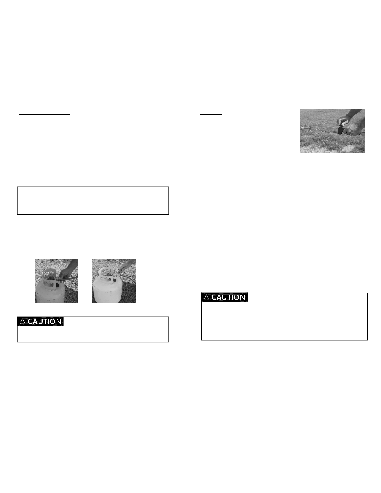
Torch Use:
1. Point torch at what you want to heat and pull Turbo Blast
Trigger to intensify the size of the flame (see Figure 7).
2. Release trigger to bring flame back to minimal level.
Figure 7
To control the size of the flame:
1. There is an adjustable brass knob used to limit the distance the Turbo Blast
Trigger can move. Turn the valve clockwise for a smaller flame.
2. Turn it counterclockwise for a larger flame.
3. As a safety precaution, these units are equipped with an excess-flow check valve
that shut off the gas in the event of a damaged or severed hose. If you allow the
flame to grow too large, the excess-flow check valve will automatically shut off gas
flow to the torch.
Shut-Off Instructions:
1. To extinguish the flame, close the torch gas flow valve.
2. Close the propane cylinder valve.
3. Open the torch-gas valve briefly to release any residual gas left in the hose.
4. Make certain that torch is completely cooled before storing. The torch nozzle will
be very hot. Do not touch it or rest it on anything that can be damaged by heat.
5. Disconnect the POL nut/nipple (located at end of hose assembly) from supply
tank by turning clockwise.
• This device is intended for outdoor use only.
• NEVER direct torch flame toward hose or gas tank.
• DO NOT leave torch unattended while in operation.
• Do not stand or prop the torch on the burner end while in operation.
• Always use integral Piezo igniter. Never use a match or lighter to ignite torch.
• DO NOT apply heat or flame to tank to check for leaks or to increase gas
pressure.
• DO NOT lift tank by the valve.
• When not in use the gas should be turned off at the LP gas tank(s).
• DO NOT place hand or body part in the path of the flame while lighting or
operating torch.
• This device is designed for vapor withdrawal from a LP gas tank(s) ONLY.
• This product produces a flame that can cause other combustible and flamma-
ble materials to burn. For example, if using the flame to soften paint on wood,
you can damage or even ignite the wood.
• Always wear ANSI-approved safety goggles when assembling and using this
product. Long sleeves, gloves and boots are recommended.
• Do not operate this product if under the influence of alcohol or drugs.
• In daylight the torch flame is barely visible. DO NOT place hand or any other
body part in the path of the flame while lighting or operating the torch.
• Before use, determine whether any materials that will be heated by the torch
will ignite, explode, or produce toxic fumes. DO NOT allow flame or heat to
come into contact with any such materials.
• Do not try to enlarge or make any modifications to the nozzle outlet. The noz-
zle and orifice are precisely matched. Any modification can create the possi-
bility of liquid propane release.
• Before each use, always check fittings and connections to make sure there
are no leaks.
• The LP tank must be on a level surface in an upright position. Do not invert or
lay tank on its side.
• Have an ABC type fire extinguisher readily accessible at the work site.
• Before each use, check gas hose for wear, cuts, or leaks. If the hose is more
than 5 years old (as marked on the hose), replace it.
• Do not attempt to repair. Contact Western for replacement under warranty.
• Be aware that the nozzle of the torch becomes vary hot when in use.
NOTE:
•
••
•
Place tank on level surface in an upright position. Do not invert or lay tank on
it side.
•
••
•
Gloves should be worn at all times when operating this device. Long sleeves,
long pants and boots are recommended.
•
••
•
Have an ABC type fire extinguisher readily accessible to the job site.
PAGE 4 OF 12 PAGE 9 OF 12
NOTE: If you have the torch gas valve open too high, when you pull the Turbo Blast
Trigger, the flame will tend to “blow out” and require re-ignition.