Western Scale M2000 User manual

DIGITAL WEIGHING SYSTEM
SECTIONAL TRUCK SCALE INSTALLATION GUIDE
FOR SOFTWARE VERSION 1.21 (MAY 2003)

M2000 DIGITAL WEIGHING SYSTEM
SECTIONAL TRUCK SCALE INSTALLATION GUIDE
Copyright © 2003 Western Scale Company Limited. All rights reserved.
Published by:
WESTERN SCALE CO. LTD.
1670 Kingsway avenue
Port Coquitlam, B.C.
Canada
V3C 3Y9
Information in this Installation Guide is subject to change without notice due to
correction or enhancement. The information described in this manual is the
property of Western Scale. No part of this manual may be reproduced or
transmitted in any form, without the express written permission of Western Scale.
Western Scale Locations
Western Scale Co. Ltd.
1670 Kingsway Avenue
Port Coquitlam, B.C.
Canada
V3C 3Y9
www.westernscale.ca
info@westernscale.ca
Wescale Inc.
DIVISION OF WESTERN SCALE
3873 Airport Way
Bellingham, WA.
USA
98227 - 9754
www.wescale.com
info@wescale.com
FOR TECHNICAL SUPPORT REGARDING THIS PRODUCT, PLEASE CALL:
1-604-941-3474

TABLE OF CONTENTS
Introduction…………………………………………………………………………………. 1
Installation Strategies…………………………………………………………….. 2
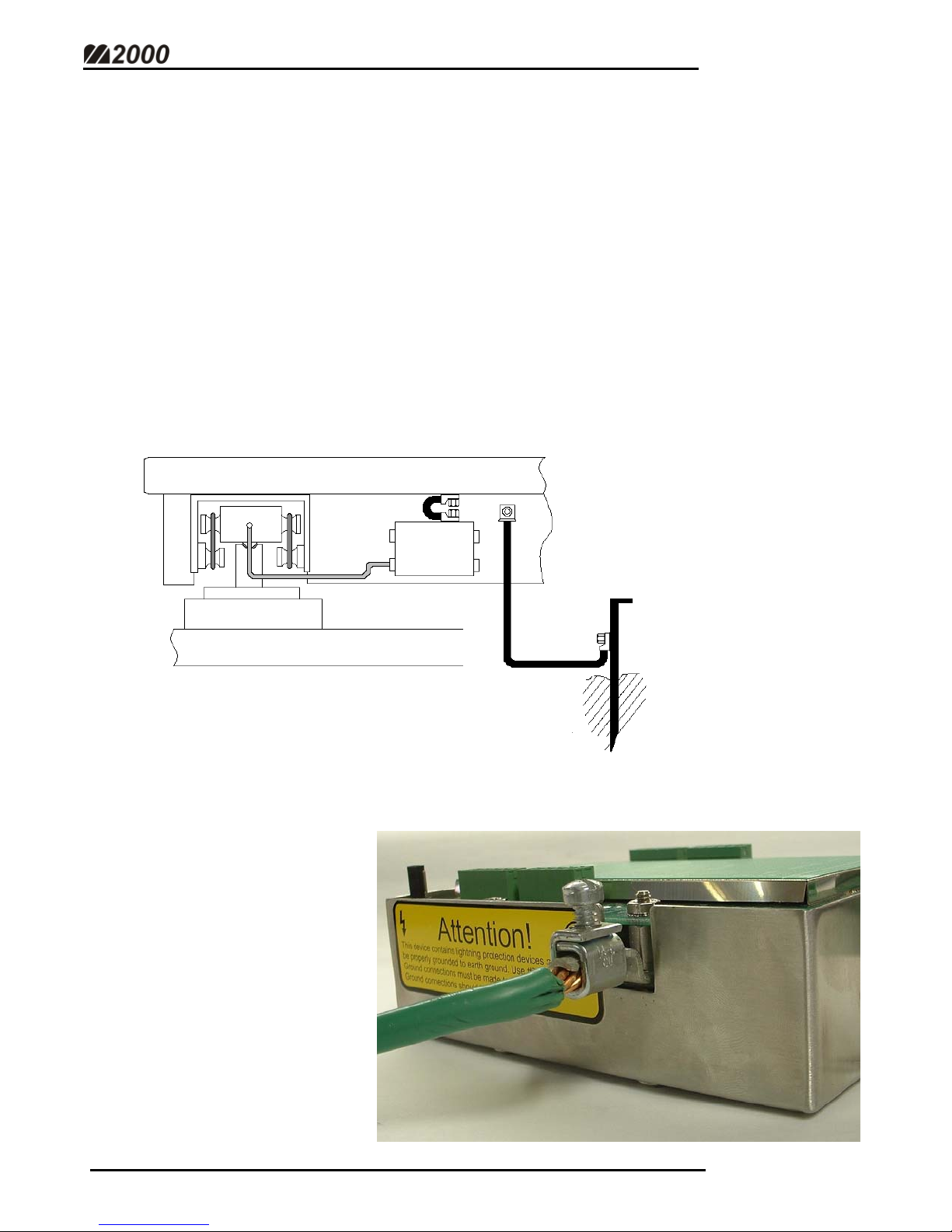
System Grounding……………………………………………………………….. 3
Getting Started…………………………………………………………………………… 4
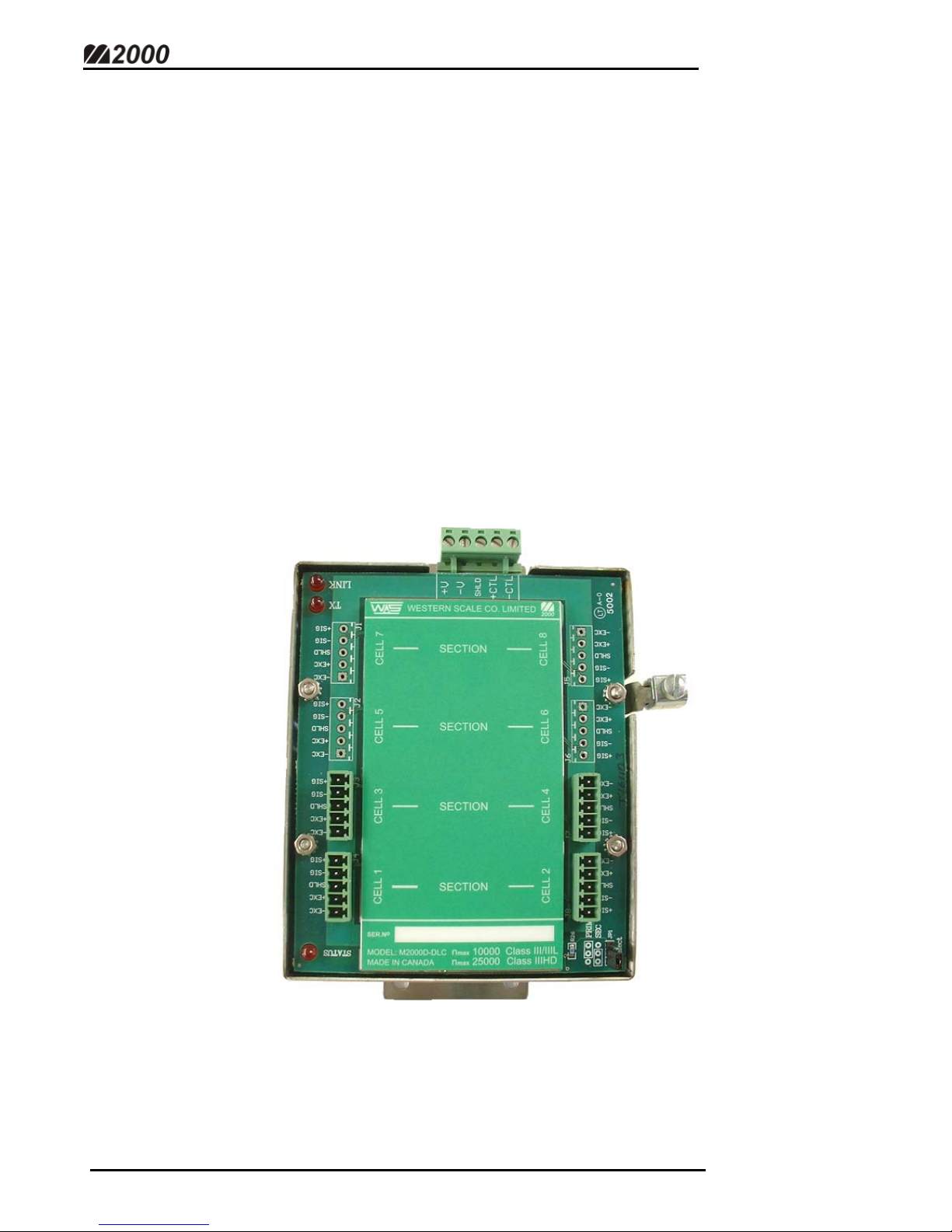
Setting the DLC ID Jumper……………………………………………………… 5
Wiring Loadcells to the DLC Smart Box………………………………………… 6
Wiring DLC Smart Boxes to the M2000D Indicator…………………………….. 7
Other Wiring to the M2000D Indicator………………………………………….. 9
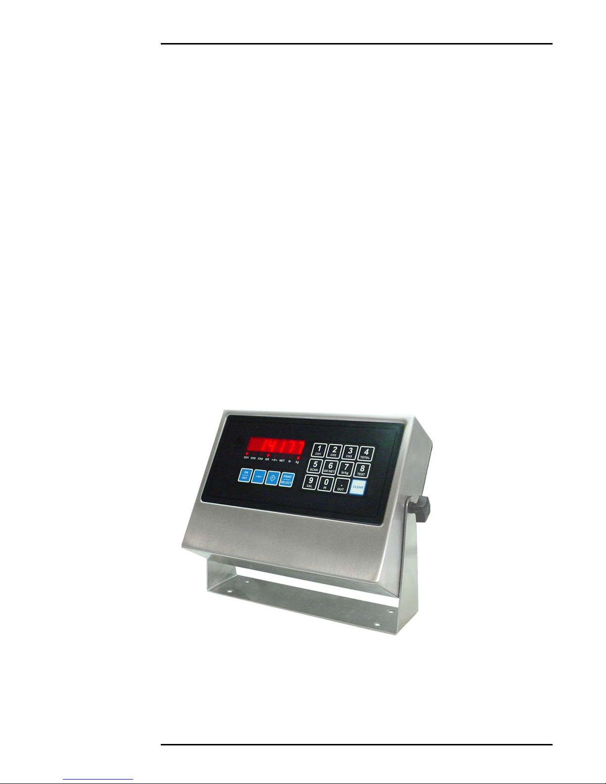
Powering Up the Indicator for the First Time…………………………………… 10
LEDs on Power Up……………………………………………………………… 10
Calibration Mode……………………………………………………………………….. 11
Entering Into Calibration Mode…………………………………………………. 11
Entering Calibration Commands………………………………………………… 11
Setting Graduation Size…………………………………………………………. 12
Setting Scale Capacity………………………………………………………….. 12
Setting Calibration Units………………………………………………………… 12
Allocating Sections……………………………………………………………… 13
Deadloading the Scale…………………………………………………………… 13
Spanning a Scale with a Test Weight…………………………………………… 14
Exit Calibration Mode…………………………………………………………… 14
Navigating the M2000………………………………………………………………….. 15
Select a Section or Cell…………………………………………………………. 16
Quick Select Method (For Sections)…………………………………………….. 17
Sectional Adjustment……………………………………………………………. 17
Example…………………………………………………………………. 18
Corner & Side-to-Side Adjustments…………………………………………….. 18
Serial Communications………………………………………………………………….. 19
Data Bits…………………………………………………………………………. 19
Baud Rate……………………………………………………………………….. 19
Parity…………………………………………………………………………….. 20
String Formats for Continuous Output………………………………………….. 20
Serial Handshaking……………………………………………………………… 21
Com Port String Output Mode…………………………………………………... 21
Configuring Com Ports to Transmit in RS422 Mode…………………………… 21
Transmission Delay for Com1 & Com2………………………………………… 22
M2000D System Specifications…………………………………………………………. 23
Appendix A - M2000 Parameters……………………………………………………….. 24
Appendix B - M2000D Specific Parameters……………………………………………. 26
Appendix C – Error Messages………………………………………………………….. 27


DIGITAL WEIGHING SYSTEM
1
INTRODUCTION
The M2000D Digital Smart Weigh System utilizes Digital Load Cell (DLC)
technology to provide high-level data integrity, easier maintenance, and lightning
protection for your weighing applications. Load cell connections to the DLC
Smart Box (mounted on the weighbridge) are the same as connections to
traditional analog summation cards. There are no pots to adjust and all sectional
adjustments are made digitally through the keypad on the M2000D indicator.
Each DLC Smart Box is available with 4, 6, or 8 load cell channels (inputs). The
M2000D indicator can support up to 2 DLC Smart Boxes for a maximum of 16
load cells (8 Sections) per scale system. DLC Smart Boxes communicate with
the indicator digitally through a current loop interface, resulting in no data
degradation for up to 1000 feet. The cable link between the M2000D indicator
and the DLC Smart Box is optically isolated and contains surge suppression
devices to help protect the scale from lightning damage.
DLC SMART BOX

2
SECTIONALTRUCKSCALE INSTALLATIONGUIDE
INSTALLATION STRATEGIES
1. Mount the DLC Smart Boxes as close as possible to the weighing
platform.
2. The DLC Smart Boxes must be mounted in a NEMA rated enclosure,
as the modules themselves are not watertight.
3. Keep cable runs between load cells and the DLC Smart Boxes as short
as possible, to help eliminate the contamination of analog load cell
signals by RFI and EMI interference.
4. Identify the end of the scale where Section 1 will be located. The DLC
Smart Box that connects to Section 1 will be configured as the Primary
DLC.
5. Observe the green Cell/Section label on the DLC Smart Box. This
label is a miniature diagram of your scale. Where the loadcell is
physically connected becomes its “Electronic Address” when
navigating the scale elements during calibration.
M2000D INDICATOR

DIGITAL WEIGHING SYSTEM
3
SYSTEM GROUNDING
The M2000 Digital System provides state of the art lightning surge protection. In
order for surge conditions to be diverted properly, a good earth ground path must
be in place. Since the M2000D indicator is optically isolated from the DLC
modules, both ends should be grounded to a good earth connection.
In most cases, the DLC Smart Box modules will be grounded to the steel
structure of the weighing platform with a braided Earth Strap. The steel frame
should be connected to a ground rod planted in the earth next to the weighing
platform. Earth Straps should be at least 8 AWG thick and preferably no longer
than 2 feet. The Earth Strap should be kept as straight as possible to reduce any
loops or kinks which may cause inductive resistances to the earth ground
discharge path.
EXAMPLE:
GROUND WIRE
FIRMLY CONNECTED
TO DLC SMART BOX
GROUND LUG
(Fig. 1)
SCALE GROUNDING
DIAGRAM (SAMPLE)

4
SECTIONALTRUCKSCALE INSTALLATIONGUIDE
GETTING STARTED
The most common Sectional Truck Scale installations have 4 sections with a
total of 8 loadcells. Due to manufacturing preferences and loadcell cable
lengths, 2 DLC Smart Box modules, each wired to 4 loadcells (2 sections) are
typically used. This type of installation will be the default example for this
guide.
• It is good practice to think of the green Cell/Section label on the DLC
Smart Box as a miniature diagram of the scale. Where a loadcell is
physically wired becomes its “Electronic Address”, used to identify the
scale elements during calibration.
• The loadcell pair comprising the 1st Section of the scale MUST ALWAYS
be wired into the connectors labeled CELL1 & CELL2. This DLC Smart
Box will be the “Primary” DLC.
• Wire the rest of the sections the same way, with odd numbered cells on
one side, even numbered cells on the other. In the case of two DLC
modules, loadcell numbering will restart at 1 on the Secondary DLC
module. (See Navigating the M2000)
Section
Cell Section
Cell
Section
Cell Section
Cell
Section
Cell Section
Cell
Section
Cell
Section
Cell
4 SECTION SCALE
(Fig. 2)

DIGITAL WEIGHING SYSTEM
5
SETTING THE DLC ID JUMPER
When using two DLC Smart Boxes, the M2000D indicator needs to differentiate
between the Primary and Secondary modules. An ID switch must be set via
the ID jumpers in the bottom right hand corner of each module. For
systems utilizing only one DLC Smart Box, the jumpers must be in the “Primary”
position.
• It is extremely important to note which module is the PRIMARY DLC as it
ALWAYS identifies the first section of the scale.
• There cannot be two primary (or two secondary) DLC Smart boxes.
Setting the switches properly is crucial for the system to function.
ID select
JP 1
PRIM
SEC
ID select
JP 1
PRIM
SEC
JUMPER
THESE TWO
PINS FOR
PRIMARY
DLC
JUMPER
THESE TWO
PINS FOR
SECONDARY
DLC
NOTE: If changing the DLC ID jumper after the initial scale setup,
the indicator must be in Calibration Mode as jumper settings are
stored with Calibration data.
(Fig. 3)

6
SECTIONALTRUCKSCALE INSTALLATIONGUIDE
WIRING LOAD CELLS TO THE DLC SMART BOX
Load cells are wired to the DLC Smart Box using 5 pin terminal connectors. The
connectors can be unplugged from the DLC to make wiring easier. The Primary
DLC Smart Box will always contain Section 1.
Loadcell connections are labeled as follows:
- EXC Negative Excitation
+ EXC Positive Excitation
SHLD Loadcell Shield
- SIG Negative Signal
+ SIG Positive Signal
Loadcell pairs in a section must be wired directly across from each other on the
DLC Smart Box. Sections are marked on the DLC module for easy reference.
(See Figure 2.)
-EXC
+EXC
-SIG
+SIG
SHLD
CELL 1
Note: The DLC Smart Box does not include SENSE line terminals
for load cells. For connecting a 6 conductor load cell cable to a DLC
terminal, it is recommended that the +SENSE and +EXCITATION
conductors to be joined together and the –SENSE and –
EXCITATION conductors to be joined together respectively.
(Fig. 4)

DIGITAL WEIGHING SYSTEM
7
WIRING THE DLC SMART BOXES TO THE M2000D INDICATOR
The scale wiring requires 2 pairs of shielded wire (one pair for power delivery and
one pair for data communications) plus a separate shield conductor. The
recommended cable type is Beldon 9873 20 AWG or equivalent. For cable runs
over 100 feet, Beldon 9773 18 AWG or equivalent is recommended.
The wires that connect the M2000D indicator to the DLC Smart Boxes are
labeled as follows:
CTRL- Current loop negative (WHITE wire)
CTRL+ Current loop positive (GREEN wire)
V+ Positive DC supply 18-24volts (RED wire)
V- Negative supply (BLACK wire)
While wiring a single DLC Smart Box to the indicator is very straightforward, two
DLC boxes will require some extra attention. The power supply V+ and V- is
wired in parallel, but the digital link, being a current loop, must be wired as shown
in Figures 5 & 6.
NOTE: When wiring the scale, power to the M2000D indicator
should be disconnected.

8
SECTIONALTRUCKSCALE INSTALLATIONGUIDE
m2000D INDICATOR m2000D INDICATOR
DLC SMART BOX
PRIMARY DLC SMART BOX
SECONDARY DLC SMART BOX
V +
V -
CTRL -
CTRL +
V +
V -
CTRL -
CTRL +
V +
V -
CTRL -
CTRL +
V +
V -
CTRL -
CTRL +
V +
V -
CTRL -
CTRL +
ONE DLC SMART BOX
TWO DLC SMART BOXES
(Fig. 6)
(Fig. 5)

DIGITAL WEIGHING SYSTEM
9
POWER
COM2 SMARTWIRE
3.3V Li
BATTERY
COM1
KEYPAD
DLC LINK
OTHER WIRING TO THE M2000D INDICATOR
All wiring to the scale indicator terminates at the main circuit board. If possible,
all wiring to the M2000D motherboard should be done before power is applied to
the unit.
CTS (Input – Printer telling the Indicator to send more data - RTS)
J1 RX (Input – Data received by the Indicator)
RS 232/422 PORT TX (Output – Data transmitted by the Indicator)
COM1 RTS (Output – Indicator signal - Readiness to receive data
COM (Ground)
CTS (Input –Printer telling the Indicator to send more data RTS)
J2 RX (Input – Data received by the Indicator)
RS 232/422 PORT TX (Output – Data transmitted by the Indicator)
COM2 RTS (Output – Indicator signal - Readiness to receive data
COM (Ground)
J3 V- (Negative )
MAIN POWER GND (Earth ground)
CONNECTOR V+(Positive power)
J5 NC (No connection)
SMARTWIRE B (RS485 differential signal)
(FOR A (RS485 differential signal)
PERIPHERAL V+ (SMARTWIRE Power supply)
INTERFACE) V- (SMA RTWIRE Power supply)
(Fig. 7)

10
SECTIONALTRUCKSCALE INSTALLATIONGUIDE
It is important to note that in very noisy industrial environments,
power-conditioning filters would be a requirement to ensure a fail-
safe operation under all conditions. Indicators should not share
AC power with electrical motors and switchgear. Consult with the
site engineer for clean AC power.
POWERING UP THE INDICATOR FOR THE FIRST TIME.
The M2000 Digital System must be used with the 12V power supply adapter
included with the indicator.
The M2000D indicator powers up and should display a scrolling “[]2000”
followed by the software version number. If this is the first time powering up the
indicator, the software version number may be followed by a set of dashes
across the display “------”. The dashes are NOT an error. They are a result
of the indicator not recognizing new DLC Smart Boxes. The DLCs must be
allocated in the indicator’s Calibration Mode. (See Allocating Sections -
Parameter 521)
LEDs ON POWER UP
There are three diagnostic LED lights on the DLC Smart Box. On power up:
1. The LINK light must be illuminated. If the LINK light is not illuminated,
there is a problem with the wiring of CTRL- and CTRL+ signals. (See
Fig. 5 & 6, Wiring the DLC Smart Box to the M2000 Indicator)
2. The STATUS light is the DLC “heartbeat“. It must be blinking. The
STATUS LED light should be blinking consistently once per second to
indicate a properly running PRIMARY DLC module. A STATUS LED
blinking rapidly 10 times per second indicates a properly functioning
SECONDARY DLC module.
3. The TX light may not be active at this point in time
STATUS LED
TX LED
LINK LED
(Fig. 8)

DIGITAL WEIGHING SYSTEM
11
19P
C12320
CALIBRATION MODE
ENTERING INTO CALIBRATION MODE
All calibration functions are executed from the keypad. Each calibration function
or parameter has a unique code with which to access and edit values.
To enter into calibration mode:
1. Enter 19 followed by the [PRINT/SELECT] key.
2. The display will flash “ PA55 ”. At this point, a four-digit
password is required.
3. Enter 1111, which is the factory default password. A blinking
“C”should appear on the left hand side of the display,
indicating Calibration Mode.
ENTERING CALIBRATION COMMANDS
Calibration parameters are selected using their unique numeric
code and the [PRINT/SELECT] key. After a parameter is selected,
its current value will be displayed. There is a 6 second window to
edit the parameter. Parameter values are entered using the
numeric keys followed by the [PRINT/SELECT] key. The [CLEAR]
key can be used to abort any parameter change.
Following are examples of setting the first 3 parameters necessary
to get the system up and running: Graduation Size, Capacity, and
Calibration Units. Remember, the indicator must be in Calibration
Mode before calibration parameters can be entered. A quick
reference list of all calibration parameters is provided. (Appendices
A & B)
Note: To calibrate Channels 2 & 3, use 29 & 39 respectively

12
SECTIONALTRUCKSCALE INSTALLATIONGUIDE
3P
4P
7P
SETTING GRADUATION SIZE (PARAMETER 3)
The factory default for Grad Size is 1. This example sets the parameter to 20.
1. To select Parameter 3, press 3on the keypad followed by
[PRINT/SELECT]. The current Grad Size is displayed.
2. Enter the new value (20) followed by the [PRINT/SELECT]
key. This saves the entry. The Grad Size is now 20.
3. To verify the change, simply access Parameter 3 again
(Press 3, [PRINT/SELECT]) and the new value of 20 should
be displayed. Hit the [CLEAR] key to cancel and return to
weighing mode.
SETTING SCALE CAPACITY (PARAMETER 4)
1. To select Parameter 4, press 4on the keypad followed by
[PRINT/SELECT]. The current capacity is displayed.
2. Enter the new capacity weight on the keypad (For Example:
100000) followed by the [PRINT/SELECT] key.
3. To verify the change, simply access Parameter 4 again
(Press 4, [PRINT/SELECT]) and the new value of should be
displayed. Hit the [CLEAR] key to cancel and return to
weighing mode.
SETTING CALIBRATION UNITS (PARAMETER 7)
1. To select Parameter 7, press 7on the keypad followed by
[PRINT/SELECT]. This will toggle the Calibration Units
between Lbs & Kgs.
2. Make sure the correct Unit Indication light is illuminated.
NOTE: ALL parameters for M2000 Indicators are entered and
edited in this wa
y
.

DIGITAL WEIGHING SYSTEM
13
521P
4P
C12320
12P
ALLOCATING SECTIONS (PARAMETER 521)
For an initial scale installation, the M2000D indicator needs to be told how many
sections are in the scale. The scale must be installed and wired to the DLC
Boxes before executing this command. There can be a maximum of 8 sections
per scale. If the DLC Smart Boxes have not been allocated, dashes will appear
on the display.
EXAMPLE: Allocate a 4 section scale (default example).
1. Press 521 on the keypad followed by the [PRINT/SELECT]
key. The message “ ALL0C” will appear on the display
followed by “5EC” (Allocate Sections).
2. Press 4followed by the [PRINT/SELECT] key. It will take a
couple of seconds for the indicator to communicate with the
DLC boxes. The display will then switch from dashes to a
weight.
DEADLOADING THE SCALE (PARAMETER 12)
Once the scale sections have been allocated, the scale must be deadloaded.
1. Remove any load from the scale.
2. Press 12 on the keypad followed by the [PRINT/SELECT]
key. “ PA55 ” will appear on the display as the password
is required to activate this command.
3. Enter the password (factory default “1111”), followed by the
[PRINT/SELECT] key to confirm. The indicator will then
deadload the scale. The display should show “0”.
Note: A 6 section scale would require a parameter value of 6

14
SECTIONALTRUCKSCALE INSTALLATIONGUIDE
13P
C10000
99P
10000
Pressing the [ON/OFF] key cycles the display between
Graduated Counts (Displayed Weight prefixed by the blinking
letter “C”) and Raw Counts (prefixed by the blinking letter “A”.)
SPANNING A SCALE WITH A TEST WEIGHT (PARAMETER 13)
1. Place your test weights on the scale.
2. Press 13 followed by the [PRINT/SELECT] key.
3. Enter the test weight value (Example: 10000) followed by the
[PRINT/SELECT] key. The indicator will calibrate the scale
and the correct weight will be displayed.
HOW TO EXIT CALIBRATION MODE (PARAMETER 99)
• To exit Calibration Mode, enter 99 followed by the
[PRINT/SELECT] key.
• The indicator display will show “Cal”, “5ave”, and “{}ait”.
• Weigh Mode will be entered with the scale weight being
displayed without the blinking “C” on the left hand side.
NOTE: None of the calibration changes are permanently saved
until Calibration Mode is exited.

DIGITAL WEIGHING SYSTEM
15
ALL CHANNELS: This is the Electronic Address for the entire
Scale. Values displayed include all Loadcells.
SECTION 1: Values displayed include Loadcells 1 & 2 combined.
SECTION 1, LOADCELL 1: Values displayed are for this Loadcell
(corner) only.
SECTION 1, LOADCELL 2: Values displayed are for this Loadcell
(corner) only.
Note: Press the [TARE] or [PRINT/SELECT] key to display the
Electronic Address Screen.
NAVIGATING THE M2000
The “Status / Electronic Address” screen appears in Calibration Mode and is
used to navigate through the various elements of the scale. Details of Scale Set-
up and Status are also displayed. The most important LED digits for navigation
are the 2nd digit (Por 5) and the last two digits ( “CH” on the diagram). These are
the “Electronic Address”.
[S] =SECTIONAL Scale
[H] = HOPPER Scale
[P] = PRIMARY DLC Smart Box
[S] = SECONDARY DLC Smart Box (if necessary)
NUMBER OF SECTIONS allocated to the scale, in this case, 4.
Each section contains 2 load cells (corners).
CHANNEL STATUS INFORMATION (USUALLY BLANK)
[E] = Faulty corner/cell. Only the faulty corner/cell will have a flashing ‘E’ in
its status field.
[D] = Corner/cell Disabled
[A] = Corner / Section Adjustment mode activated.
[_] = Cell allocated to another scale or not accessible to the user
(Fig. 9)

16
SECTIONALTRUCKSCALE INSTALLATIONGUIDE
P
P
T
T
OR
SELECT A SECTION OR CELL (SCROLLING METHOD)
Starting with the scale as a whole, sections and individual cells may be selected
easily, using their “Electronic Address”.
1. Press the [TARE] or [PRINT/SELECT] key to display the
Electronic Address screen. The address of the currently
selected scale element will appear.
Before the indicator returns to weight display,
2. Press the [TARE] key to scroll forward through the scale
elements’ Electronic Addresses, OR…
3. Press the [PRINT/SELECT] key to scroll backwards.
EXAMPLE: Scrolling forward through all the sections and cells in a 4 section
truck scale with 2 DLCs.
Status-Electronic Address
Screen Description
5P 4.1.C Section 1 Combination. The total of the 2 cells in Section 1
5P 4.1.1 Section 1, Cell (corner) 1. For Individual Cell Adjustments
5P 4.1.2 Section 1, Cell (corner) 2. For Individual Cell Adjustments
5P 4.2.C Section 2 Combination. The total of the 2 cells in Section 2
5P 4.2.3 Section 2, Cell (corner) 3. For Individual Cell Adjustments
5P 4.2.4 Section 2, Cell (corner) 4. For Individual Cell Adjustments
*55 4.3.C Section 3 Combination. The total of the 2 cells in Section 3
*Note Address located on SECONDARY DLC
55 4.3.1* Section 3, Cell (corner) 1. For Individual Cell Adjustments
*Note Loadcell # 1 SECONDARY DLC
55 4.3.2 Section 3, Cell (corner) 2. For Individual Cell Adjustments
55 4.4.C Section 4 Combination. The total of the 2 cells in Section 4
55 4.4.3 Section 4, Cell (corner) 3. For Individual Cell Adjustments
55 4.4.4 Section 4, Cell (corner) 4. For Individual Cell Adjustments
Other manuals for M2000
1
Table of contents
Other Western Scale Accessories manuals